400W
400W
C
L
A
M
P
r
es
p
o
n
d
i
n
g
t
o
t
h
e
E
ur
o
p
e
a
n
R
e
g
.
n
.
2
4
4
/
2
0
0
9
E
F
F
I
C
I
E
N
C
Y
C
L
A
S
S
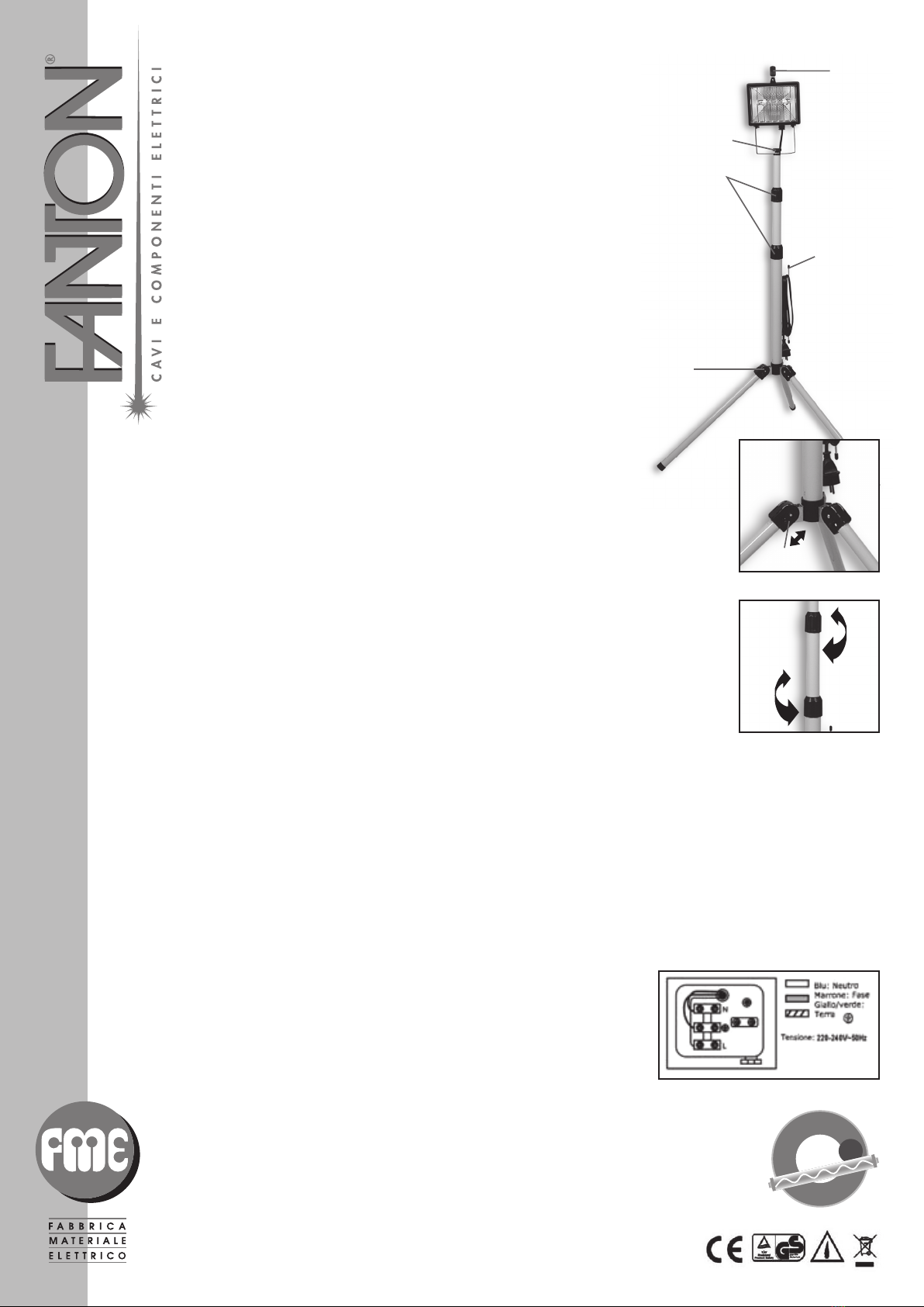
HALOGEN FLOODLIGHT TRIOD
62602 (500W, 220-240V~50Hz)
62612 (500W, 220-240V~50Hz)
INSTRUCTION
Important safety information
This unit is suitable for external use only when used correctly..
Caution
This unit can become extremely hot whilst in operation: do not touch the unit until it has had time to cool
down. Make sure the floodlights are far enough away from any combustible materials and/or surfaces. Make
sure there is adequate ventilation to aid heat dissipation.
Assembly
The tripod stand is supplied assembled. To attach the floodlights you must first erect the stand.
To open the legs push the spring pin upwards and, at the same time, pivot the leg down.
Release the spring pin whist pivoting the leg and the pin will locate into one slot (fig. 1)
To alter the stand height twist the locks (B) anti-clockwise to release, slide the tubes to desired height and
tighten the twist locks clockwise (fig. 2).
Unscrew the center knob (A). Position the center hole on the floodlight bracket over the top of the stand.
Re-insert the center screw knob (A). The floodlight can be swivelled, if required, by loosening the center screw
knob (A), rotating the floodlight to the desired angle, and re-tightening the center screw knob (A). The stand
has an integral cable tidy (D).
For safe stoage of the mains cable when not in use.
To adjust the floodlights angle, loosen the screws located on either side of the bracket, until the desired angle
is achieved, then re-tighten.
Check the floodlight is secure and that the stand is stable and has a fim footing. Ensure cable is not catching
on any sharp object and that the mains plug connection is adequately protected against rain or moisture. Your
worklight is now ready for use.
Fitting the Bulb
To fit the supplied halogen bulbs you need to loosen the screw (E) securing the hinged front cover and swing
the cover down. The bulb is attached by spring-loaded holders at each end. Gently locate the bulb into position
ensuring good contact at both ends. Take care not to touch the glass of the bulb. If this does clean the bulb
with methylated spirit. Close the hinged front cover and re-tighten the top retaining screw (E).
DO NOT OVERTIGHTEN, THIS MAY DAMAGE THE GLASS.
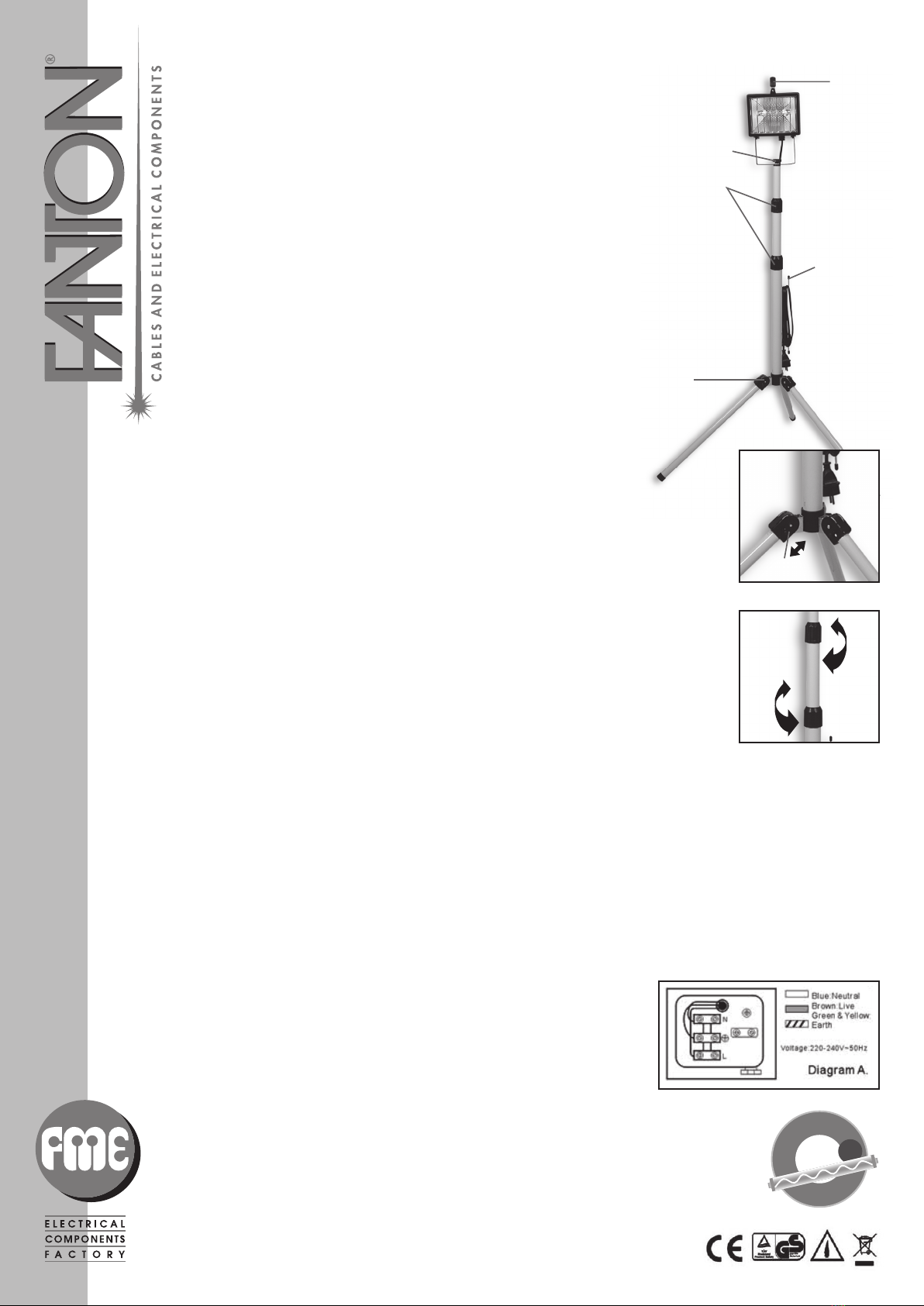
Electrical Safety
These worklights must be earthed. If il becomes necessary to re-wire the plug please follow these guidelines.
Always secure wires in plug termilals carefully. Make sure the cable is firmly located in the cord grip NEVER
connect the green & yellow wire to any terminal other one marked with the eart symbol ‘E’ or Regularly inspect
all electrical connections and for damage. Any faults should be immediately rectified before furthed use of the
worklight. Always have the winng and connections checked by a qualified electrcian. In use, ensure all wiring
and extension cable are kept clear of any cutting tools sharp objects and any other potential hazard such as wet
floors, chemicals, solvents etc.
Note: If your mains wiring differs in any way from Diagram A. Consult a qualified electrician. Always ensurethat
the mains supply voltage is correct Always replace the fuse with one of an identical rating.
The lighting direction can not be adjusted down ward.
You can contact with the manufactory or service department of specialized in making the cable or equipment if
the cable was destroye.
Specification
220V-240V~50Hz
Power: MAX500W
Dustproof & Waterproof grade: IP54
Halogen bulb junction R7s length 118mm cod. 62603
Powder cord: H07RN-F 3G1,0mm23m
Max height of stand: 2m
Tempered glass: 177x140x5mm cod. 62604
MADE IN CHINA
IMT1009
Parts identification
AAdjustment screw
BFerrule
CLock
DCable holder
ECover retaining screw and handle
A
B
E
D
Wiring System
Fig. 1
Spring Pin
Fig. 2
C