Expolite TourLED City User manual

User Manual
TourLED City

17
ABLE OFCONTENTS
T
PART 1 PRODUCT SPECIFICATIONS...........................................1.
1.1--PRODUCT FEATURES.................................................................1.
1.2--TECHNICAL SPECIFICATIONS.....................................................1.
1.3--DIMENSIONS...............................................................................1.
PART 2 INSTALLATION...............................................................3.
2.1--MOUNTING..................................................................................3.
2.3--SIGNAL CONNECTIONS...............................................................4.
2.2--POWER CONNECTIONS...............................................................4.
PART 4 USING DMX512 CONTROLLER......................................11.
4.1--BASIC ADDRESSING ................................................................ 11.
PART 3 USING CODER.................................................................5.
PART 5 OPERATION WITH WIRELESS DMX................................16.
3.1--BASIC..........................................................................................5.
3.3--EDIT STATIC COLOUR..................................................................7.
3.2--MENU..........................................................................................6.
3.4--ACTIVATINGAUTO PROGRAMS...................................................7.
3.7--PERSONALITY............................................................................8.
1.4--SAFETY WARNING......................................................................2.
3.9--SPECIAL SETTINGS....................................................................8.
3.10--EDITING CUSTOM PROGRAMS.................................................9.
3.8--ID ADDRESS...............................................................................8.
PART6 APPENDIX......................................................................18.
6.1--MAINTENANCE.........................................................................18.
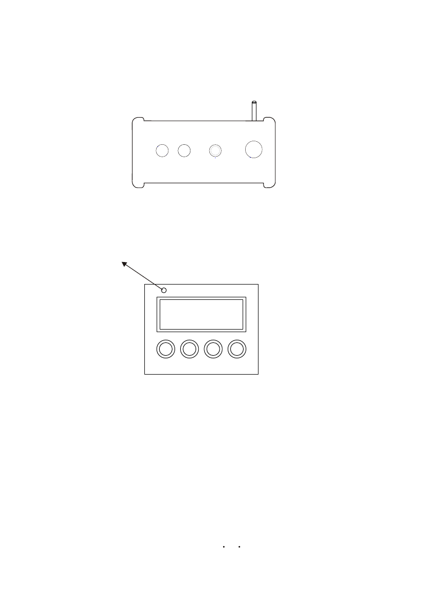
5.4 By pressing the RESETbutton on W-DMX transmitter, transmitterwill searchfor RESET
lighting fixtures. During search transmittergreen SIGNALindicatorwill flash. After
pairing with lighting fixture green SIGNALindicator will display.
POWER SIGNAL
ANTENNA
RESET
5.5 Once a lighting fixturehas been paired with a W-DMX transmitter, the greenSIGNALindicator
will display. Once a lightingfixture has been paired witha W-DMX transmitter, the lighting
fixture cannot be paired with another W-DMX transmitter. If a lighting fixture requires pairing
with anewW-DMX transmitter, steps5.3 and 5.4 must be repeated.
SET UP DOWN
MENU
WDMX green signalindicator LED
4.2--CHANNEL ASSIGNMENT........................................................... 11.
3.5--DMX512 SETTINGS......................................................................7.
3.6--RUN MODE..................................................................................8.
3.11--WHITES CALIBRATION..............................................................9.
3.13--WDMX SETTINGS...................................................................10.
3.10--ACTIVATE THEPASSWORD.....................................................10.
3.12--RGB CALIBRATION.................................................................10.

116
1 PRODUCTSPECIFICATIONS
1.1 PRODUCTFEATURES
LED FIXTURE
* Setting:LED display
* Operation:DMX512/Static Play/Custion/Wireless
* Function:RGBW 0-100%dimming;Linear/Nonlineardimming;RGBW Calibration;
* Installation:Bracket
* Power:3 corein
* Data :5core in/out cable
1.2 TECHNICALSPECIFICATIONS
LED MODULE
Dimensions
LED MODULE:
Voltage
Power
Weight
808x252x567mm
40Kg
100~240V...50/60Hz
650W
Operation Temperature -40 ~45 (operating)
-20 ~45 (startup)
IP 67
GREEN
IP RATING
WHITE 3W x 24
3W x 44
RED
3W x 44
BLUE 3W x 44
1.3 DIMENSIONS
5.2 Select DMXfrom the <RUN>menu.
5.3 SelectACTI from the<WDMX> menu andproceed to turnON the WDMX.
If the WDMXreceiver card isalready paired witha WDMX transmitterthen
the fixture isready for receivingDMX signal. Ifthe WDMX receivercard needs
to be pairedwith a newWDMX transmitter,select YESfrom the <WDMX>/<REST>
menu. Thegreen signal indicatorLED will notshow which confirmsthat WDMX receiver
card is unpairedand ready fornew pairing.
5OPERATION WITH WIRELESS DMX
5.1 When using this lighting fixture with W-DMX receiver installed inside,
the fixture may be placed at a range of 300m from W-DMX transmitter
W-DMX TRANSMITTER
LED325XWAT
AMBER 3W x 24

152
1.4 SAFETY WARNING
IMPORTANT
ALWAYS READ THEUSER MANUAL BEFOREOPERATION.
PLEASE CONFIRM THAT THE POWERSUPPLYSTATED ON THEPRODUCT IS THE
SAME ASTHE MAINS POWERSUPPLYIN YOURAREA.
This product mustbe installed bya qualified professional.
Always operatethe equipment asdescribed in theuser manual.
A minimum distance of 0.5m must be maintained between the equipment and
combustible surface.
The product mustalways be placedin a wellventilated area.
Always makesure that theequipment is installedsecurely.
DO NOT standclose to theequipment and staredirectly into theLED light source.
Always disconnectthe power supplybefore attempting maintenance.
Always make sure that the supporting structure is solid and can support the combined
weight of theproducts.
The earth wiremust always beconnected to theground.
Do not touchthe power cablesif your handsare wet.
ATTENTION
This product leftthe place ofmanufacture in perfectcondition. In orderto maintain this
condition and forsafe operation, theuser must alwaysfollow the instructionsand safety warnings
described in thisuser manual.
Avoid shakingor strong impactsto any partof the equipment.
Make sure thatall parts ofthe equipment arekept clean andfree of dust.
Always makesure that thepower connections areconnected correct andsecure.
If there isany malfunction ofthe equipment, contactyour distributor immediately.
When transferring theproduct, it isadvisable to usethe original packagingin which the
product left thefactory.
Shields, lenses orultraviolet screens shallbe changed ifthey have becomedamaged to such
an extent thattheir effectiveness isimpaired.
I t isimportant that thepower cable isfrequently inspected toensure that thereis no damagein
any position. Ifthe power cableis damaged inany way,it should bereplaced by aqualified electrical
technician.
The lamp (LED)shall be changedif it hasbecome damaged orthermally deformed.
1
2
0 255
3
0 255
0 255
HSV
1
2
0 255
3
4
0 255
0 255
0 255
50 255
AR3.S
70 255
1
2
0 255
3
4
0 255
0 255
0 255
BLOCK
5
60 255
7
8
0 255
0 255
0 255
CHANNEL FUNCTION
VALUE
CHANNEL FUNCTIONVALUE
CHANNEL FUNCTIONVALUE
RED
GREEN
BLUE
MASTER DIMMER
WHITE
STROBE
MODULE1 WHITE
MODULE1 BLUE
MODULE1 GREEN
MODULE1 RED
MODULE2 WHITE
MODULE2 BLUE
MODULE2 GREEN
MODULE2 RED
VALUE(0~100%)
SATURATION(0~100%)
HUE(0~100%)
60 255 AMBER
0 255 MODULE1 AMBER
9
10 0 255 MODULE2 AMBER

314
HANGING:
Ensure that fixtureis mounted toa structure thatis correct andsuitable for hanging
this kind oflighting fixture
Mounting structure shouldwithhold load often times fixtureweight
Fixture is mountedusing mounting bracketand clamps (seediagram)
A safetycable should always be used with this lighting fixture(safety cable should
withstand ten timeslighting fixture weight)a
2.1-2
2.1 MOUNTING
UPRIGHT
2 INSTALLATION
The LED Fixturecan be mountedin a sittingor wall mountedposition using the
supporting brackets.
The LED Fixtureshould be placedon a non-flammableflat surface inany orientation
and fixed byscrews. There arefour holes intothe supporting bracket.
1
2
0 255
3
0 255
0 255
1
2
0 255
3
4
0 255
0 255
0 255
1
2
0 255
3
4
0 255
0 255
0 255
ARC.1
AR1.D
ARC.3
1
2
0 255
3
4
0 255
0 255
0 255
50 255
AR3.D
CHANNEL FUNCTIONVALUE
CHANNEL FUNCTION
VALUE
CHANNEL FUNCTION
VALUE
CHANNEL FUNCTIONVALUE
RED
GREEN
BLUE
RED
GREEN
BLUE
MASTER DIMMER
RED
GREEN
BLUE
WHITE
RED
GREEN
BLUE
MASTER DIMMER
WHITE
50 255 AMBER
60 255 AMBER

413
Data L Data N
GND E
AC Power IN
E3
23
1
DMX IN
32
1
DMX OUT
1 -GND
2 -Data -
3 -Data +
2.2 POWER CONNECTIONS
2.3 SIGNAL CONNECTIONS
ID21
ID22
210
211
ID20
200 209
ID19
190 199
ID18
180 189
ID14
ID15
ID16
ID17
140 149
150 159
160 169
170 179
ID65
ID66
254
255
ID8
ID9
ID10
ID11
ID12
ID13
80 89
90 99
100 109
110 119
120 129
130 139
ID1~ID66
ID1
ID2
ID3
ID4
ID5
0 9
10 19
20 29
30 39
40 49
50 59
ID6
ID7
60 69
70 79
17
0 9
30 69
70 129
130 189
190 255
16
10 29
CHANNEL FUNCTIONVALUE
DIMMING SPEED
PRESET DIMMER SPEEDFROM DISPLAYMENU
LINEAR DIMMER
NON LINEAR DIMMER 1 fastest
NON LINEAR DIMMER 2
NON LINEAR DIMMER 3
NON LINEAR DIMMER 4 slowest
ID ADDRESS

12 5
SET UP DOWN
MENU
3.1 BASIC
3 USING CODER
The LED fixtureis mounted witha LCD displayand 4 controlbuttons.
enter the currentlyselected menu orconfirm the currentfunction value
scroll 'UP' through the menu listor increase the value of thecurrent function
scroll'DOWN' through the menulistor decrease the value ofthe current function
scroll through themain menu orreturn to themain menu
MENU
ENTER
WHITE7 6500K
WHITE8 7200K
231 235
236 240
WHITE9 8000K
WHITE10 8500K
WHITE11 10000K
241 245
246 250
251 255
13
14
0 10
11 255
141 150
151 160
161 170
171 180
181 190
191 200
201 210
211 220
221 230
231 255
91 100
101
110
111 120
121 130
AUTO6
AUTO7
AUTO8
AUTO9
131 140 AUTO10
0 40
41 50
51 60
61 70
71 80
81 90
AUTO 1
AUTO 2
AUTO3
AUTO4
AUTO5
0 255
15
12
WHITE1 3200K
WHITE2 3400K
WHITE3 4200K
WHITE4 4900K
WHITE5 5600K
WHITE6 5900K
171 200
201 205
206 210
211 215
216 220
221 225
226 230
RED100%/GREEN 100%P/BLUE100%/WHITE 100%/AMBER 100%
91 110
111 130
131 150
RED UP/GREEN 0%/BLUE100%
RED100%/GREEN 0%/BLU EDOWN
RED100%/GREEN UP/BLUE UP
151 170 RED DOWN/GREEN DOWN/BLUE 100%
CHANNEL FUNCTIONVALUE
CHANNEL FUNCTIONVALUE
NO FUNCTION
STROBE
1~20Hz
AUTO
NO FUNCTION
AUTO SPEED ADJUSTMENT
When usingCH14,AUTO01-AUTO10, this function activated
PR.01
PR.02
PR.03
PR.04
PR.05
PR.06
PR.07
PR.08
PR.09
PR.10

116
RUN DMX
SLAV
AT.01
AT.02
AT.10
AUTO
PR.01
PR.02
PR.10
D.(001~512)
ADDR
ID
I.(01~66)
TOUR
ARC.1
ARC.3
AR1.D
AR3.S
AR3.D
MENU
RED
GREN
BLUE
WHIT
R.(0~255)
G.(0~255)
B.(0~255)
W.(0~255)
STRB
S.(0~20)
STAT
PERS
HSV
SET UPLD
ID.ON ON
OFF
REST
RGBW
COLOR
DIM1
DIM3
DIM2
DIM4
DIM
UC
OFF
OFF
BLOC
PASS
PASS SEND END
REST END
PR.01
PR.02
PR.10
SC.01
SC.02
SC.30
RED
GREN
BLUE
WHIT
STRB
TIME
FADE
EDIT
KEY ON
OFF
WH.01
WH.02
WH.11
RED
GREN
BLUE
WHIT
R.(0~255)
G.(0~255)
B.(0~255)
W.(0~255)
CAL1
RGB.W RED
GREN
BLUE
R.(0~255)
G.(0~255)
B.(0~255)
CAL2
ACTI ON
OFF
WDMX
REST NO
YES
R.(0~255)
G.(0~255)
B.(0~255)
W.(0~255)
S.(0~20)
T.(0~255)
F.(0~255)
3.2 MENU
AMBE
A.(0~255)
AMBE A.(0~255)
AMBE
A.(0~255)
1
2
0 255
3
4
0 255
0 255
0 255
50 255
6
7
8
0 255
0 255
0 255
9
0 255
71 90 RED 0%/GREEN DOWN/BLUE100%
0 5
11
30
31 50
51 70
NO FUNCTION
RED100%/GREEN UP/BLUE0%
RED DOWN/GREEN 100%/BLUE0%
RED 0%/GREEN 100%/BLUEUP
10
TOUR
4.2 CHANNELASSIGNMENT
Note:This product haseight DMX512 channelconfigurations: TOUR
..D AR3 AR3
.
ARC 1 AR1 ARC.3 .D .S HSV
and BLOC
CHANNEL FUNCTIONVALUE
MASTER DIMMER
MODULE1 WHITE
MODULE1 BLUE
MODULE1 GREEN
MODULE1 RED
MODULE2 WHITE
MODULE2 BLUE
MODULE2 GREEN
MODULE2 RED
4.1 BASICADDRESSING
Set the DMX512address in the DMX menu.
It is possible to have the same DMX address or independent
addresses for eachfixture.
4 USINGADMX512 CONTROLLER
(or STEP TIME when CUS.01-CUS.10 in Ch14 is activated)
(or FADE TIME when CUS.01-CUS.10 in Ch14 is activated)
0 255 MODULE1 AMBER
0 255
11
MODULE2 AMBER
12

710
3.3 EDIT STATIC COLOUR
STATIC COLOUR
Combine Red , Green , Blue , White , Amber and Amber
to create an infinite range of colors (0-255)
Set the value of the Strobe (0-20Hz)
MENU Red
Green
Blue
White
(0~255)
(0~255)
(0~255)
(0~255)
Strob (0~20)
STAT
3.4 ACTIVATINGAUTOPROGRAMS
AUTO
Select the target AUTO program and press ENTER .
Programs AT.01 to AT.10 are fully pre-programmed and will not be
altered by changes in EDIT mode.
Programs PR.01 to PR.10 are fully pre-programmed and can be edited
in EDIT mode.
AT.01
AT.02
AT.10
AUTO
PR.01
PR.02
PR.10
MENU
3.5 DMX512 SETTINGS
DMX
Enter the DMX mode to set the DMXADDRESS.
D(001~512)
DMX
MENU
Amber (0~255)
Amber (0~255)
CAL2
Enter the CAL2 to adjust the RGB parameter to make different whites.
CAL2
When the new setting is activated, the DMX controller choose
RGB = 255,255,255, the white color will be made by the actual RGB values on
the .
3.12 RGB CALIBRATION
RGBW Red
Green
Blue
(0~255)
(0~255)
(0~255)
CAL2
MENU
ACTI ON
OFF
WDMX
REST NO
YES
MENU
WDMX
Enter WDMX menu to changeWDMX settings
Enter the ACTI menu to turnON/OFF WDMX functionality
Enter the REST menu to resetthe WDMX pairing(note that onlywhen
the WDMX receivercard is resetcan it bepaired with a new WDMX
transmitter card)
KEY ON
OFF
MENU
3.14 ACTIVATE THE PASSWORD
KEY
Enter the KEY mode to select whether the access password is on or off.
When the fixture is set as PASS ON , after 30 seconds or turn on the fixture
next time, the fixture will need an access password to enter the display menu
control.
Note: The factory access password is UP +DOWN +UP +DOWN ,
then press ENTER to confirm the access.
3.13 WDMX SETTINGS

98
3.7 PERSONALITY
PERSONALITY
Enter the PERSONALITY mode to select DMX mode: TOUR , ARC.1 ,
AR1.D , ARC.3 , AR3.D , AR3.S , HSV or BLOC .
3.8 IDADDRESS
ID
Enter the ID mode to set the IDADDRESS.
ID
ID(01~66)
MENU
RUN
Enter the RUN mode to set working mode.
DMX mode is for using the DMX512 controller to control the fixtures.
SLAV mode is for Master -- Slave operation.
3.6 RUN MODE
RUN DMX
SLAV
MENU
TOUR
ARC.1
ARC.3
AR1.D
AR3.S
AR3.D
PERS
HSV
BLOC
MENU
3.9 SPECIAL SETTINGS
SET UPLD
ID.ON ON
OFF
REST
RGBW
COLOR
DIM1
DIM3
DIM2
DIM4
DIM
UC
OFF
OFF
PASS
PASS SEND END
REST END
MENU
SETTING
Select UPLD to upload thecustom programs fromthe current MASTERunit to
the SLAVEunits.
In order toactivate the uploadfunction the passwordmust be entered.
Password is thesame as themain access password.
When uploading theMASTER and SLAVE units willdisplay YELLOW.
If an erroroccurs when uploadingthe MASTER and/orSLAVE unitswill display RED.
On successful uploadingof the customprograms the MASTERand SLAVEunits
will display GREEN.
In order toreset custom modesto default valuesselect REST .
Enter ID in order toallow/disallow ID addressfunction from theDMX512
controller.
COLOR is for activate/unactivatethe color calibrationfunctions.
When RGBW is selected, onRGB = 255,255,255, the color isdisplayed as calibrated
in CAL2 --RGBW. When COLOR is set OFF , on RGB= 255,255,255, the RGB
values are notadjusted and the output is mostpowerful.
When [UC] is selected,the RGB outputare adjusted toa standard presetuniversal color
which balances fixturesfrom different generations..
PR.01
PR.02
PR.10
SC.01
SC.02
SC.30
Red
Green
Blue
White
Strobe
Time
Fade
(0~255)
(0~255)
(0~255)
(0~255)
(0~20)
(0~255)
(0~255)
EDIT
MENU
3.10 EDITING CUSTOMPROGRAMS
EDIT CUSTOM
Enter the EDIT mode to editthe custom programs PR.01 to PR.10 .
Each custom programhas 30 stepsthat can beedited.
Each step allowsthe creation ofa scene usingRED Red , GREEN Green ,
BLUE Blue , WHITE White ,AMBER Amber , STROBE Strobe , TIME
Time & FADE Fade .
WT01
WT02
WT11
Red
Green
Blue
White
(0~255)
(0~255)
(0~255)
(0~255)
CAL1
MENU
CAL1
Enter the CAL1 to select white color of different color temperature.
There are 11 pre-programmed White colors can be edited by using Red ,
Green , Blue , White & Amber .
3.11 WHITES CALIBRATION
Amber (0~255)
Amber
(0~255)

710
3.3 EDIT STATIC COLOUR
STATIC COLOUR
Combine Red , Green , Blue , White , Amber and Amber
to create an infinite range of colors (0-255)
Set the value of the Strobe (0-20Hz)
MENU Red
Green
Blue
White
(0~255)
(0~255)
(0~255)
(0~255)
Strob (0~20)
STAT
3.4 ACTIVATINGAUTOPROGRAMS
AUTO
Select the target AUTO program and press ENTER .
Programs AT.01 to AT.10 are fully pre-programmed and will not be
altered by changes in EDIT mode.
Programs PR.01 to PR.10 are fully pre-programmed and can be edited
in EDIT mode.
AT.01
AT.02
AT.10
AUTO
PR.01
PR.02
PR.10
MENU
3.5 DMX512 SETTINGS
DMX
Enter the DMX mode to set the DMXADDRESS.
D(001~512)
DMX
MENU
Amber (0~255)
Amber (0~255)
CAL2
Enter the CAL2 to adjust the RGB parameter to make different whites.
CAL2
When the new setting is activated, the DMX controller choose
RGB = 255,255,255, the white color will be made by the actual RGB values on
the .
3.12 RGB CALIBRATION
RGBW Red
Green
Blue
(0~255)
(0~255)
(0~255)
CAL2
MENU
ACTI ON
OFF
WDMX
REST NO
YES
MENU
WDMX
Enter WDMX menu to changeWDMX settings
Enter the ACTI menu to turnON/OFF WDMX functionality
Enter the REST menu to resetthe WDMX pairing(note that onlywhen
the WDMX receivercard is resetcan it bepaired with a new WDMX
transmitter card)
KEY ON
OFF
MENU
3.14 ACTIVATE THE PASSWORD
KEY
Enter the KEY mode to select whether the access password is on or off.
When the fixture is set as PASS ON , after 30 seconds or turn on the fixture
next time, the fixture will need an access password to enter the display menu
control.
Note: The factory access password is UP +DOWN +UP +DOWN ,
then press ENTER to confirm the access.
3.13 WDMX SETTINGS

116
RUN DMX
SLAV
AT.01
AT.02
AT.10
AUTO
PR.01
PR.02
PR.10
D.(001~512)
ADDR
ID
I.(01~66)
TOUR
ARC.1
ARC.3
AR1.D
AR3.S
AR3.D
MENU
RED
GREN
BLUE
WHIT
R.(0~255)
G.(0~255)
B.(0~255)
W.(0~255)
STRB
S.(0~20)
STAT
PERS
HSV
SET UPLD
ID.ON ON
OFF
REST
RGBW
COLOR
DIM1
DIM3
DIM2
DIM4
DIM
UC
OFF
OFF
BLOC
PASS
PASS SEND END
REST END
PR.01
PR.02
PR.10
SC.01
SC.02
SC.30
RED
GREN
BLUE
WHIT
STRB
TIME
FADE
EDIT
KEY ON
OFF
WH.01
WH.02
WH.11
RED
GREN
BLUE
WHIT
R.(0~255)
G.(0~255)
B.(0~255)
W.(0~255)
CAL1
RGB.W RED
GREN
BLUE
R.(0~255)
G.(0~255)
B.(0~255)
CAL2
ACTI ON
OFF
WDMX
REST NO
YES
R.(0~255)
G.(0~255)
B.(0~255)
W.(0~255)
S.(0~20)
T.(0~255)
F.(0~255)
3.2 MENU
AMBE
A.(0~255)
AMBE A.(0~255)
AMBE
A.(0~255)
1
2
0 255
3
4
0 255
0 255
0 255
50 255
6
7
8
0 255
0 255
0 255
9
0 255
71 90 RED 0%/GREEN DOWN/BLUE100%
0 5
11
30
31 50
51 70
NO FUNCTION
RED100%/GREEN UP/BLUE0%
RED DOWN/GREEN 100%/BLUE0%
RED 0%/GREEN 100%/BLUEUP
10
TOUR
4.2 CHANNELASSIGNMENT
Note:This product haseight DMX512 channelconfigurations: TOUR
..D AR3 AR3
.
ARC 1 AR1 ARC.3 .D .S HSV
and BLOC
CHANNEL FUNCTIONVALUE
MASTER DIMMER
MODULE1 WHITE
MODULE1 BLUE
MODULE1 GREEN
MODULE1 RED
MODULE2 WHITE
MODULE2 BLUE
MODULE2 GREEN
MODULE2 RED
4.1 BASICADDRESSING
Set the DMX512address in the DMX menu.
It is possible to have the same DMX address or independent
addresses for eachfixture.
4 USINGADMX512 CONTROLLER
(or STEP TIME when CUS.01-CUS.10 in Ch14 is activated)
(or FADE TIME when CUS.01-CUS.10 in Ch14 is activated)
0 255 MODULE1 AMBER
0 255
11
MODULE2 AMBER
12

12 5
SET UP DOWN
MENU
3.1 BASIC
3 USING CODER
The LED fixtureis mounted witha LCD displayand 4 controlbuttons.
enter the currentlyselected menu orconfirm the currentfunction value
scroll 'UP' through the menu listor increase the value of thecurrent function
scroll'DOWN' through the menulistor decrease the value ofthe current function
scroll through themain menu orreturn to themain menu
MENU
ENTER
WHITE7 6500K
WHITE8 7200K
231 235
236 240
WHITE9 8000K
WHITE10 8500K
WHITE11 10000K
241 245
246 250
251 255
13
14
0 10
11 255
141 150
151 160
161 170
171 180
181 190
191 200
201 210
211 220
221 230
231 255
91 100
101
110
111 120
121 130
AUTO6
AUTO7
AUTO8
AUTO9
131 140 AUTO10
0 40
41 50
51 60
61 70
71 80
81 90
AUTO 1
AUTO 2
AUTO3
AUTO4
AUTO5
0 255
15
12
WHITE1 3200K
WHITE2 3400K
WHITE3 4200K
WHITE4 4900K
WHITE5 5600K
WHITE6 5900K
171 200
201 205
206 210
211 215
216 220
221 225
226 230
RED100%/GREEN 100%P/BLUE100%/WHITE 100%/AMBER 100%
91 110
111 130
131 150
RED UP/GREEN 0%/BLUE100%
RED100%/GREEN 0%/BLU EDOWN
RED100%/GREEN UP/BLUE UP
151 170 RED DOWN/GREEN DOWN/BLUE 100%
CHANNEL FUNCTIONVALUE
CHANNEL FUNCTIONVALUE
NO FUNCTION
STROBE
1~20Hz
AUTO
NO FUNCTION
AUTO SPEED ADJUSTMENT
When usingCH14,AUTO01-AUTO10, this function activated
PR.01
PR.02
PR.03
PR.04
PR.05
PR.06
PR.07
PR.08
PR.09
PR.10

413
Data L Data N
GND E
AC Power IN
E3
23
1
DMX IN
32
1
DMX OUT
1 -GND
2 -Data -
3 -Data +
2.2 POWER CONNECTIONS
2.3 SIGNAL CONNECTIONS
ID21
ID22
210
211
ID20
200 209
ID19
190 199
ID18
180 189
ID14
ID15
ID16
ID17
140 149
150 159
160 169
170 179
ID65
ID66
254
255
ID8
ID9
ID10
ID11
ID12
ID13
80 89
90 99
100 109
110 119
120 129
130 139
ID1~ID66
ID1
ID2
ID3
ID4
ID5
0 9
10 19
20 29
30 39
40 49
50 59
ID6
ID7
60 69
70 79
17
0 9
30 69
70 129
130 189
190 255
16
10 29
CHANNEL FUNCTIONVALUE
DIMMING SPEED
PRESET DIMMER SPEEDFROM DISPLAYMENU
LINEAR DIMMER
NON LINEAR DIMMER 1 fastest
NON LINEAR DIMMER 2
NON LINEAR DIMMER 3
NON LINEAR DIMMER 4 slowest
ID ADDRESS

314
HANGING:
Ensure that fixtureis mounted toa structure thatis correct andsuitable for hanging
this kind oflighting fixture
Mounting structure shouldwithhold load often times fixtureweight
Fixture is mountedusing mounting bracketand clamps (seediagram)
A safetycable should always be used with this lighting fixture(safety cable should
withstand ten timeslighting fixture weight)a
2.1-2
2.1 MOUNTING
UPRIGHT
2 INSTALLATION
The LED Fixturecan be mountedin a sittingor wall mountedposition using the
supporting brackets.
The LED Fixtureshould be placedon a non-flammableflat surface inany orientation
and fixed byscrews. There arefour holes intothe supporting bracket.
1
2
0 255
3
0 255
0 255
1
2
0 255
3
4
0 255
0 255
0 255
1
2
0 255
3
4
0 255
0 255
0 255
ARC.1
AR1.D
ARC.3
1
2
0 255
3
4
0 255
0 255
0 255
50 255
AR3.D
CHANNEL FUNCTIONVALUE
CHANNEL FUNCTION
VALUE
CHANNEL FUNCTION
VALUE
CHANNEL FUNCTIONVALUE
RED
GREEN
BLUE
RED
GREEN
BLUE
MASTER DIMMER
RED
GREEN
BLUE
WHITE
RED
GREEN
BLUE
MASTER DIMMER
WHITE
50 255 AMBER
60 255 AMBER

152
1.4 SAFETY WARNING
IMPORTANT
ALWAYS READ THEUSER MANUAL BEFOREOPERATION.
PLEASE CONFIRM THAT THE POWERSUPPLYSTATED ON THEPRODUCT IS THE
SAME ASTHE MAINS POWERSUPPLYIN YOURAREA.
This product mustbe installed bya qualified professional.
Always operatethe equipment asdescribed in theuser manual.
A minimum distance of 0.5m must be maintained between the equipment and
combustible surface.
The product mustalways be placedin a wellventilated area.
Always makesure that theequipment is installedsecurely.
DO NOT standclose to theequipment and staredirectly into theLED light source.
Always disconnectthe power supplybefore attempting maintenance.
Always make sure that the supporting structure is solid and can support the combined
weight of theproducts.
The earth wiremust always beconnected to theground.
Do not touchthe power cablesif your handsare wet.
ATTENTION
This product leftthe place ofmanufacture in perfectcondition. In orderto maintain this
condition and forsafe operation, theuser must alwaysfollow the instructionsand safety warnings
described in thisuser manual.
Avoid shakingor strong impactsto any partof the equipment.
Make sure thatall parts ofthe equipment arekept clean andfree of dust.
Always makesure that thepower connections areconnected correct andsecure.
If there isany malfunction ofthe equipment, contactyour distributor immediately.
When transferring theproduct, it isadvisable to usethe original packagingin which the
product left thefactory.
Shields, lenses orultraviolet screens shallbe changed ifthey have becomedamaged to such
an extent thattheir effectiveness isimpaired.
I t isimportant that thepower cable isfrequently inspected toensure that thereis no damagein
any position. Ifthe power cableis damaged inany way,it should bereplaced by aqualified electrical
technician.
The lamp (LED)shall be changedif it hasbecome damaged orthermally deformed.
1
2
0 255
3
0 255
0 255
HSV
1
2
0 255
3
4
0 255
0 255
0 255
50 255
AR3.S
70 255
1
2
0 255
3
4
0 255
0 255
0 255
BLOCK
5
60 255
7
8
0 255
0 255
0 255
CHANNEL FUNCTION
VALUE
CHANNEL FUNCTIONVALUE
CHANNEL FUNCTIONVALUE
RED
GREEN
BLUE
MASTER DIMMER
WHITE
STROBE
MODULE1 WHITE
MODULE1 BLUE
MODULE1 GREEN
MODULE1 RED
MODULE2 WHITE
MODULE2 BLUE
MODULE2 GREEN
MODULE2 RED
VALUE(0~100%)
SATURATION(0~100%)
HUE(0~100%)
60 255 AMBER
0 255 MODULE1 AMBER
9
10 0 255 MODULE2 AMBER

116
1 PRODUCTSPECIFICATIONS
1.1 PRODUCTFEATURES
LED FIXTURE
* Setting:LED display
* Operation:DMX512/Static Play/Custion/Wireless
* Function:RGBW 0-100%dimming;Linear/Nonlineardimming;RGBW Calibration;
* Installation:Bracket
* Power:3 corein
* Data :5core in/out cable
1.2 TECHNICALSPECIFICATIONS
LED MODULE
Dimensions
LED MODULE:
Voltage
Power
Weight
808x252x567mm
40Kg
100~240V...50/60Hz
650W
Operation Temperature -40 ~45 (operating)
-20 ~45 (startup)
IP 67
GREEN
IP RATING
WHITE 3W x 24
3W x 44
RED
3W x 44
BLUE 3W x 44
1.3 DIMENSIONS
5.2 Select DMXfrom the <RUN>menu.
5.3 SelectACTI from the<WDMX> menu andproceed to turnON the WDMX.
If the WDMXreceiver card isalready paired witha WDMX transmitterthen
the fixture isready for receivingDMX signal. Ifthe WDMX receivercard needs
to be pairedwith a newWDMX transmitter,select YESfrom the <WDMX>/<REST>
menu. Thegreen signal indicatorLED will notshow which confirmsthat WDMX receiver
card is unpairedand ready fornew pairing.
5OPERATION WITH WIRELESS DMX
5.1 When using this lighting fixture with W-DMX receiver installed inside,
the fixture may be placed at a range of 300m from W-DMX transmitter
W-DMX TRANSMITTER
LED325XWAT
AMBER 3W x 24
17
ABLE OFCONTENTS
T
PART 1 PRODUCT SPECIFICATIONS...........................................1.
1.1--PRODUCT FEATURES.................................................................1.
1.2--TECHNICAL SPECIFICATIONS.....................................................1.
1.3--DIMENSIONS...............................................................................1.
PART 2 INSTALLATION...............................................................3.
2.1--MOUNTING..................................................................................3.
2.3--SIGNAL CONNECTIONS...............................................................4.
2.2--POWER CONNECTIONS...............................................................4.
PART 4 USING DMX512 CONTROLLER......................................11.
4.1--BASIC ADDRESSING ................................................................ 11.
PART 3 USING CODER.................................................................5.
PART 5 OPERATION WITH WIRELESS DMX................................16.
3.1--BASIC..........................................................................................5.
3.3--EDIT STATIC COLOUR..................................................................7.
3.2--MENU..........................................................................................6.
3.4--ACTIVATINGAUTO PROGRAMS...................................................7.
3.7--PERSONALITY............................................................................8.
1.4--SAFETY WARNING......................................................................2.
3.9--SPECIAL SETTINGS....................................................................8.
3.10--EDITING CUSTOM PROGRAMS.................................................9.
3.8--ID ADDRESS...............................................................................8.
PART6 APPENDIX......................................................................18.
6.1--MAINTENANCE.........................................................................18.
5.4 By pressing the RESETbutton onW-DMX transmitter, transmitter willsearch for RESET
lighting fixtures. During search transmittergreen SIGNALindicator will flash. After
pairing with lighting fixture green SIGNALindicator will display.
POWER SIGNAL
ANTENNA
RESET
5.5 Once a lighting fixturehas been paired with a W-DMX transmitter, the greenSIGNALindicator
will display. Once a lightingfixture has been paired witha W-DMX transmitter, the lighting
fixture cannot be paired with another W-DMX transmitter. If a lighting fixture requires pairing
with anew W-DMX transmitter, steps 5.3and 5.4 must be repeated.
SET UP DOWN
MENU
WDMX green signalindicator LED
4.2--CHANNEL ASSIGNMENT........................................................... 11.
3.5--DMX512 SETTINGS......................................................................7.
3.6--RUN MODE..................................................................................8.
3.11--WHITES CALIBRATION..............................................................9.
3.13--WDMX SETTINGS...................................................................10.
3.10--ACTIVATE THEPASSWORD.....................................................10.
3.12--RGB CALIBRATION.................................................................10.

6 APPENDIX
6.1 MAINTENANCE
Isolator sheetIsolator sheet
Thermal protection deviceThermal protection device
Head casing front sectionHead casing front section
Head casing gasketHead casing gasket
Head casing main sectionHead casing main section
Rotating bracket 2Rotating bracket 2
Pressure valvePressure valve
Watertight strain reliefWatertight strain relief
Power supply casing setPower supply casing set
W-DMX antenna (optional)W-DMX antenna (optional)
Quick-lockQuick-lock
Mounting bracket 1Mounting bracket 1
Mounting rodMounting rod
Adjusting screwAdjusting screw
Mounting bracket 2Mounting bracket 2
Mounting frame setMounting frame set
Head casing setHead casing set
LED driverLED driver
Power supply connection boardPower supply connection board
Signal connection boardSignal connection board
Connection boardConnection board
Power supply casing gasketPower supply casing gasket
Power supply casing main sectionPower supply casing main section
Pressure valvePressure valve
Watertight strain reliefWatertight strain relief
Watertight strain reliefWatertight strain relief
NONO ITEMITEM
Base handleBase handle
Tempered glassTempered glass
Lens board 1Lens board 1
LensLens
Lens board 2Lens board 2
LED boardLED board
FanFan
Power supplyPower supply
Mounting rodMounting rod
Rotating bracket 1Rotating bracket 1
Head extrusionHead extrusion
Display PCBDisplay PCB
18
Table of contents
Other Expolite Floodlight manuals

Expolite
Expolite TourLED Pro 28 TW Zoom User manual

Expolite
Expolite Tour-Flash Pro User manual

Expolite
Expolite LED FRESNEL MINI LED22812 User manual

Expolite
Expolite led22115 User manual

Expolite
Expolite TourLED Pro 28 TW Zoom User manual

Expolite
Expolite led22775 User manual

Expolite
Expolite TourWash 9I User manual

Expolite
Expolite AkkuLED Tough 9 User manual
Popular Floodlight manuals by other brands

COLORKINETICS
COLORKINETICS ColorBlast 12 user guide

Osram
Osram NOXLITE LED HP FLOODLIGHT II manual

Lightmaxx
Lightmaxx LIG0010511-000 user manual

DIODE LED
DIODE LED VOLANTE LED Flood Light installation guide

Digital Lighting Systems
Digital Lighting Systems Animation Series user manual

BEGA
BEGA 77 362 Instructions for use


