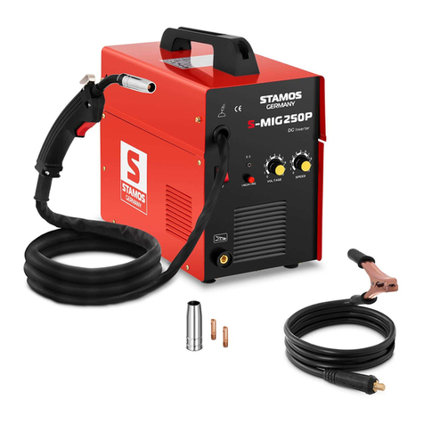
Expondo STAMOS S-MIGMA 250.IGBT User manual

S-MIGMA-250.IGBT
USER MANUAL | INSTRUKCJA OBSŁUGI | MANUEL D‘UTILISATION | ISTRUZIONI D`USO | MANUAL DE INSTRUCCIONES
BEDIENUNGSANLEITUNG
expondo.de

2 3
Rev. 27.03.2017 Rev. 27.03.2017
DE
EN
PL
CZ
FR
IT
ES
3
10
18
26
34
42
50
DE
INHALT | CONTENT | CONTENU | CONTENIDO | TREŚĆ | CONTENUTO
DE
SYMBOLE
Lesen Sie die Bedienungsanleitung sorgfältig.
Elektrische Geräte dürfen nicht mit dem Hausmüll entsorgt werden.
Das Gerät entspricht der CE-Erklärung.
Tragen Sie Ganzkörperschutzkleidung!
Achtung! Schutzhandschuhe tragen.
Es ist eine Schutzbrille zu verwenden.
Es sind Schutzschuhe zu tragen.
Achtung! Heiße Oberäche – Verbrennungsrisiko!
Achtung! Brand – oder Explosionsrisiko.
Warnung! Schädliche Dämpfe, Vergiftungsgefahr! Gase und Dämpfe können gesundheitsgefährdend
sein. Beim Schweißen werden Schweißgase und – dämpfe freigesetzt.
Einatmen dieser Substanzen kann die Gesundheit gefährden.
Es ist eine Schweißmaske mit Schutzlter zu verwenden.
Warnung! Schädliche Strahlung des Schweißbogens
Keine unter Spannung stehenden Teile berühren.
ACHTUNG! Die Bilder in der vorliegenden Anleitung sind Übersichtsbilder und können in Bezug
auf einzelne Details von dem tatsächlichen Aussehen abweichen.
Die ursprüngliche Bedienungsanleitung ist die deutschsprachige Fassung. Sonstige Sprachfassungen sind
Übersetzungen aus der deutschen Sprache.
1. SICHERHEITSHINWEISE
1.1 ALLGEMEINE BEMERKUNGEN
• Sorgen Sie für die eigene, sowie für die Sicherheit Dritter und befolgen Sie die in der Bedienungsanleitung
enthaltenen Anweisungen genau.
• Für die Inbetriebnahme, Bedienung, Reparatur und den Maschinenbetrieb dürfen nur entsprechend
qualizierte Personen zuständig sein.
• Das Gerät ist ausschließlich gemäß seines Zweckes zu benutzen.
1.2 VORBEREITUNG DER SCHWEISSARBEITSSTELLE
BEIM SCHWEISSEN KANN ES ZUM BRAND ODER ZUR EXPLOSION KOMMEN
• Die Sicherheits – und Arbeitsschutzvorschriften in Bezug auf Schweißen sind zu befolgen. Die
Arbeitsstelle muss mit einem geeigneten Feuerlöscher ausgerüstet werden.
• Das Schweißen ist an den Stellen, wo es zur Entzündung von leicht entammbaren Werkstoffen
kommen kann, verboten.
• Das Schweißen ist verboten, wenn sich in der Luft entammbare Partikel oder Dämpfe benden.
• Alle brennbaren Werkstoffe, innerhalb einer Reichweite von 12 m von der Schweißstelle, sind zu
entfernen oder nach Möglichkeit mit einer feuerfesten Decke zu schützen.
• Es sind Schutzmaßnahmen gegen Funken und glühende Metallpartikel zu ergreifen.
• Es sollte insbesondere darauf geachtet werden, dass Funken oder heiße Metallspritzer nicht durch
Schlitze oder Öffnungen im Gehäuse, oder durch den Schutzschirm gelangen können.
• Es dürfen keine Behälter oder Fässer geschweißt werden, die leichtbrennbare Substanzen enthalten
oder enthielten. Das Schweißen in der unmittelbaren Nähe ist ebenfalls untersagt.
• Es dürfen keine Druckbehälter, Drucktanks oder Leitungen von Druckanlagen geschweißt werden.
• Sorgen Sie immer für ausreichende Belüftung!
• Nehmen Sie für die Schweißarbeit eine stabile Position ein.
NAZWA PRODUKTU SPAWARKA
PRODUKTNAME SCHWEISSGERÄT
PRODUCT NAME WELDING MACHINE
NOM DU PRODUIT POSTE À SOUDER
NOME DEL PRODOTTO SALDATRICE
NOMBRE DEL PRODUCTO EQUIPO DE SOLDAR
NÁZEV VÝROBKU
MODEL PRODUKTU
MODELL
PRODUCT MODEL
MODÈLE
MODELLO
MODELO
MODEL VÝROBKU
NAZWA PRODUCENTA
NAME DES HERSTELLERS
MANUFACTURER NAME
NOM DU FABRICANT
NOME DEL PRODUTTORE
NOMBRE DEL FABRICANTE
NÁZEV VÝROBCE
ADRES PRODUCENTA
ANSCHRIFT DES HERSTELLERS
MANUFACTURER ADDRESS
ADRESSE DU FABRICANT
INDIRIZZO DEL FORNITORE
ADRESA VÝROBCE

4 5
Rev. 27.03.2017 Rev. 27.03.2017
1.3 PERSÖNLICHE SCHUTZMITTEL
DIE STRAHLUNG DES ELEKTRISCHEN BOGENS KANN AUGENLEIDEN UND
HAUTSTÖRUNGEN VERURSACHEN.
• Beim Schweißen tragen Sie bitte eine saubere, feuerfeste und nicht leitende Schutzkleidung ohne
Ölspuren (Leder, dicke Baumwolle, Schweißerhandschuhe, Lederschürze, Sicherheitsschuhe).
• Vor dem Beginn der Arbeit sind alle leicht brennbaren oder explosiven Gegenstände oder Materialien,
wie Propan-Butan, Feuerzeuge oder Streichhölzer außer Reichweite zu bringen.
• Verwenden Sie einen Gesichtsschutz (Helm oder Haube) und einen Augenschutz mit einem
entsprechenden Verdunklungslter, der das Sehvermögen des Schweißers und für den Schweißstromwert
geeignet ist. Die Sicherheitsstandards geben den Farbton Nr. 9 (min. Nr. 8) für jede Stromstärke unter
300 A vor. Niedrigere Werte dürfen verwendet werden, wenn der Bogen den bearbeiteten Gegenstand
überdeckt.
• Verwenden Sie immer eine Schutzbrille mit Seitenschutz und entsprechender Zulassung bzw. eine
andere Schutzabdeckung.
• Verwenden Sie Schutzabdeckungen an der Arbeitsstelle, um andere Personen vor dem blendenden
Licht oder den Spritzern zu schützen.
• Tragen Sie immer Ohrstöpsel oder sonstige Hörschutzmittel, um sich gegen überhöhte Lärmwerte und
vor den Funken zu schützen.
• Unbeteiligte Personen sind bezüglich der Gefahren durch das Schauen auf den elektrischen Bogen zu
warnen.
1.4 STROMSCHLAGSCHUTZ
STROMSCHLAG KANN ZUM TODE FÜHREN
• Die Stromversorgungsleitung ist an die am nächsten gelegene Steckdose anzuschließen. Vermeiden Sie
eine fahrlässige Kabelverteilung im Raum und auf nicht kontrollierten Oberächen, da dem Benutzer
ein Stromschlag oder ein Brand drohen kann.
• Ein Kontakt mit den elektrisch geladenen Teilen kann zu einem Stromschlag oder zu einer ernsthaften
Verbrennung führen.
• Der Lichtbogen und der Arbeitsbereich sind bei Stromdurchuss elektrisch geladen.
• Der Eingangskreislauf und der interne Stromkreislauf stehen ständig unter Spannung.
• Die Bauteile, die unter Spannung stehen, dürfen nicht berührt werden.
• Es sind Isolierungsmatten oder sonstige Isolierungsbeschichtungen auf dem Boden zu verwenden. Diese
müssen ausreichend groß sein, sodass der Kontakt des Körpers mit dem Gegenstand oder mit dem
Boden nicht möglich ist.
• Verwenden Sie trockene und unbeschädigte Handschuhe, sowie passende Schutzkleidung.
• Der elektrische Bogen darf nicht berührt werden.
• Vor der Reinigung oder dem Austausch der Elektrode ist die Stromversorgung abzuschalten.
• Man sollte überprüfen, ob das Erdungskabel sowie der Stecker an die geerdete Steckdose richtig angeschlossen
wurde. Falscher Anschluss der Geräteerdung kann zur Gefahr für Leben oder Gesundheit führen.
• Man sollte die Stromkabel regelmäßig in Bezug auf Beschädigungen oder mangelnde Isolierung
überprüfen. Das beschädigte Kabel ist auszutauschen. Die fahrlässige Reparatur der Isolierung kann
zum Tod oder Gesundheitsproblemen führen.
• Bei Nichtbenutzung muss das Gerät ausgeschaltet werden.
• Das Kabel darf nicht um den Körper herum gewickelt werden.
• Der geschweißte Gegenstand ist richtig zu erden.
• Das Gerät darf ausschließlich im einwandfreien Zustand verwendet werden.
• Beschädigte Bestandteile des Gerätes sind zu reparieren oder auszutauschen. Bei Höhenarbeiten sind
Sicherheitsgurte zu verwenden.
• Alle Bestandteile der Ausrüstung und der Sicherheitsgeräte sollten an einer Stelle aufbewahrt werden.
• Bei der Einschaltung des Gerätes ist das Griffende möglichst weit vom Körper zu halten.
• Das Massekabel ist möglichst nah an dem geschweißten Element anzuschließen (z.B. am Arbeitstisch).
NACH DEM ABSCHALTEN DES VERSORGUNGSKABELS KANN DAS GERÄT UNTER
SPANNUNG STEHEN.
• Überprüfen Sie nach dem Ausschalten des Gerätes und dem Abschalten des Spannungskabels die
Spannung am Eingangskondensator, um sicherzugehen, dass der Spannungswert gleich Null ist.
Andernfalls dürfen die Bauteile des Gerätes nicht berührt werden.
DE DE
1.5 GAS UND RAUCH
ACHTUNG! GAS KANN GEFÄHRLICH FÜR DIE GESUNDHEIT SEIN UND SOGAR
ZUM TOD FÜHREN.
• Man muss immer eine gewisse Entfernung vom Gasauslauf einhalten.
• Beim Schweißen ist für gute Belüftung zu sorgen. Das Einatmen des Gases ist zu vermeiden.
• Von der Oberäche der geschweißten Gegenstände sind die chemischen Substanzen (Schmiersubstanzen,
Lösungsmittel) zu entfernen, da sie unter Einuss der Temperatur verbrennen und dabei gefährliche
gasförmige Substanzen freisetzen.
• Das Schweißen von verzinkten Teilen ist nur bei vorhandenen, leistungsfähigen Abzügen, mit der
Möglichkeit der Filtrierung und Zuführung von reiner Luft, zulässig. Die Zinkdämpfe sind sehr giftig. Ein
Symptom der Vergiftung ist das sog. Zinkeber.
2. TECHNISCHE DATEN
Produktname Schweißgerät
Modell S-MIGMA 250.IGBT
Katalognummer 2208
Nenneingangsspannung / Netzfrequenz 230V~ / 50 Hz
Nenneingangsstrom [A] 33 (MMA)
22.5 (WIG)
29.5 (MIG)
Leerlaufspannung [V] 62 (MMA / WIG / MIG)
Schweißstrom MMA [A] 10-250
Schweißstrom WIG [A] 10-250
Schweißstrom MIG[A] 50-250
Schweißstrom im Arbeitszyklus 60% [A] 250 (MMA/WIG/MIG)
Schweißstrom im Arbeitszyklus 100% [A] 193 (MMA/WIG/MIG)
3. BETRIEB
3.1 ALLGEMEINE BEMERKUNGEN
• Das Gerät ist zweckgemäß, unter Einhaltung der Arbeitsschutzvorschriften und den Angaben aus dem
Typenschild zu verwenden (IP-Grad, Arbeitszyklus, Versorgungsspannung etc.).
• Die Maschine darf nicht geöffnet werden. Andernfalls erlischt die Garantie. Die explodierenden, nicht
abgedeckten Bestandteile können zu Körperverletzungen führen
• Der Hersteller haftet nicht bei technischen Änderungen des Geräts oder materiellen Schäden infolge
dieser Änderungen.
• Bei Störungen des Gerätes wenden Sie sich bitte an die Serviceabteilung des Verkäufers.
• Belüftungsschlitze dürfen nicht zugedeckt werden. Das Schweißgerät ist in ca. 30 cm Entfernung von den
umliegenden Gegenständen aufzustellen.
• Das Schweißgerät darf weder in Körpernähe noch unter dem Arm gehalten werden.
• Die Maschine darf nicht in Räumen verwendet werden, in denen hohe Abgaswerte oder viel Staub
auftreten. Auch in Räumen in denen sich Geräte benden, die hohe Werte elektromagnetischer
Emissionen aufweisen, sollte das Schweißgerät nicht verwendet werden.
3.2 LAGERUNG DES GERÄTES
• Die Maschine ist vor Wasser und vor Feuchtigkeit zu schützen.
• Die Schweißmaschine darf nicht auf eine heiße Oberäche gestellt werden.
• Das Gerät ist in einem trockenen und sauberen Raum zu lagern.

6 7
Rev. 27.03.2017 Rev. 27.03.2017
3.3 ANSCHLUSS DES GERÄTES
3.3.1 Stromanschluss
• Die Überprüfung des Stromanschlusses ist durch eine qualizierte Person durchzuführen. Darüber
hinaus sollte eine entsprechend qualizierte Person überprüfen, ob die Erdung und elektrische Anlage
den Sicherheitseinrichtungen und den – vorschriften entsprechen und sachgerecht funktionieren.
• Das Gerät ist in der Nähe des Arbeitsortes aufzustellen.
• Der Anschluss von übermäßig langen Leitungen an die Maschine sollte vermieden werden.
• Einphasige Schweißmaschinen sollten an eine Steckdose angeschlossen werden, die mit einem
Erdungsstecker ausgerüstet ist.
• Die Schweißgeräte, die aus dem dreiphasigen Netz versorgt werden, werden ohne Stecker geliefert.
Der Stecker muss selbständig beschafft werden. Mit der Montage ist eine dazu qualizierte Person zu
beauftragen.
ACHTUNG! DAS GERÄT DARF NUR BETRIEBEN WERDEN, WENN DIE ANLAGE ÜBER EINE
FUNKTIONSFÄHIGE SICHERUNG VERFÜGT!
4. BEDIENUNG
SCHWEIßERANLAGE: S-MIGMA 250.IGBT (2208)
DE DE
Beschreibung des Geräts:
Nr. Funktion und Beschreibung
1. STÖRUNGSANZEIGE = Bei folgenden zwei Situationen geht die Lampe an:
a) Wenn die Maschine eine Fehlfunktion hat und nicht betrieben werden kann.
b) Wenn das Schweißgerät die standardmäßige Belastungsdauer überschreitet, setzt der
Schutzmodus ein und die Maschine stellt ihre Funktion ein. Das heißt, dass das Gerät nun ausläuft
um die Temperaturkontrolle wieder her zu stellen, nachdem das Gerät überhitzt wurde. Die
Maschine kommt aus diesem Grunde zum Stillstand. Während dieses Vorgangs leuchtet die rote
Warnleuchte an der Frontverkleidung auf. In diesem Fall müssen Sie nicht den Stromstecker aus
der Steckdose entfernen. Zum Abkühlen der Maschine kann so nämlich die Lüftung weiter arbeiten
um die Kühlung voranzutreiben. Wenn das rote Licht nicht mehr leuchtet ist die Temperatur nun
zurück auf die normale Betriebstemperatur gesunken und das Gerät kann wieder in Betrieb
genommen werden.
2. Kontrollleuchte Stromversorgung. EIN
3Drehknopf zur Einstellung der Drahtvorschubgeschwindigkeit
4. Drehknopf zur Einstellung der Spannung im MIG-Verfahren
5. Drehknopf zur Einstellung des Stroms im WIG – / MMA-Verfahren
6. WIG/MIG – MMA-Schalter
7. Drahtvorschub-Taste: Nach dem Drücken dieser Taste beginnt die Schweißanlage mit der
Drahtzuführung. Der Draht wird bis zum Loslassen der Taste weiter zugeführt. Er dient der
Kontrolle der Zuführungsgeschwindigkeit oder des Drahtzuführungsverfahrens selbst, z.B. nach
dem Austausch der Drahtrolle.
8. Anschlussstelle der WIG-Steuerungstaste
9. Gasanschlussstelle WIG-Verfahren
10. Leitungsausgang „–”
11. Leitungsausgang „+”
12. Plug zur Polarisationsänderung:
Verbunden mit dem positiven Pol :MIG-Schweißen
Verbunden mit dem negativen Pol: FLUX-Schweißen
13. Anschlussstelle MIG
14. Hauptschalter
15. Anschlusssteckdose des Erhitzers an CO2 – Gas – 230V~
16. Gasanschluss im WIG-Verfahren
17. Gasanschluss im MIG-Verfahren
18. Stromversorgungsleitung
19. Drahtrolle
20. Drahtführungsschiene
21. Leitung für die Polarisierungsänderung im MIG/FLUX-Schweißen
Hinteransicht:
Innenansicht:
1
2
34
5
67
8
9
11
13
12
10
Vorderansicht:
14 15 16 17
18
20
19
21
1. Düse
2. Endstück
3. MIG-Schweißgriff
1
2
3MIG Griff:

8 9
Rev. 27.03.2017 Rev. 27.03.2017
1
2
3
4
5
1. Haube lang, hinten
2. Spannhülse
3. Brennerhalte
4. Spannbüchse im Gehäuse
5. Keramikdüse
TIG Griff:
5. ANSCHLUSS DER LEITUNGEN
BESCHREIBUNGEN:
SCHWEISSMODUS MMA
1. MMA-Funktion ist mit dem Schalter (Nr. 6) auszuwählen.
2. Die Masseleitung ist an den mit dem Zeichen „+” (Nr. 11) gekennzeichneten Anschluss richtig
anzuschließen.
3. Danach ist die Schweißleitung an den mit dem Zeichen „-” (Nr. 10) gekennzeichneten Anschluss
richtig anzubringen. ACHTUNG! Die Polarisierung der Leitungen kann sich unterscheiden! Alle
Informationen bezüglich der Polarisierung sollten in der, durch den Elektrodenhersteller mitgelieferten,
Bedienungsanleitung zu nden sein!
4. Nun kann die Netzleitung angeschlossen und die Stromversorgung aktiviert werden. Nach Anschluss
der Masseleitung an den, zu schweißenden, Gegenstand kann mit der Arbeit begonnen werden.
SCHWEIßMODUS: WIG
Vor dem Schweißen im WIG-Verfahren ist die Gasasche an die Steckdose des hinteren Teils des Geräts, Nr.
10 (TIG GAS; in der Zeichnung), anzuschließen.
1. MIG/WIG mit dem Schalter (Nr. 6) auswählen.
2. Die Massenleitung an den mit dem Zeichen „+” (Nr.11) gekennzeichneten Anschluss richtig anschließen.
3. Danach die WIG – Schweißleitung an den mit dem Zeichen „-” (Nr. 10) gekennzeichneten Anschluss
anbringen, außerdem kann nun die WIG Steuerleitung (Nr. 8) angeschlossen werden. Als nächstes ist die
Gasleitung in die Anschlussstelle (Nr. 9) im vorderen Teil des Geräts anzuschließen.
4. Jetzt kann die Netzleitung angeschlossen und Stromversorgung aktiviert werden. Nach dem Anschluss
der Masseleitung an den zu schweißenden Gegenstand kann mit der Arbeit begonnen werden.
SCHWEIßMODUS: MIG
Vor dem MIG-Schweißvorgang sollte die Gasasche an die Anschlussstelle Nr. 17 MIG GAS (Auf der
Rückseite des Gerätes) angeschlossen werden. Danach kann die Leitung für die Polarisierungsänderung im
MIG/FLUX-Schweißen an das Verbindungsstück „+” Nr.11 (auf der Zeichnung) und an das Verbindungsstück
Nr. 12 (ebenfalls auf der Zeichnung) angeschlossen werden.
1. MIG/WIG-Schweißfunktion auf dem Umschalter (Nr. 6) auswählen.
2. Das Massekabel an das Verbindungsstück „-” (Nr. 10) anschließen.
3. Nun kann der richtige Schweißdraht eingelegt, das Netzkabel angeschlossen und die Energieversorgung
aktiviert werden. Nach dem Anschließen des Massekabels an den zu schweißenden Gegenstand kann
man mit der Arbeit beginnen.
SCHWEIßMODUS: FLUX
Vor dem FLUX-Schweißvorgang sollte die Leitung für die Polarisierungsänderung im MIG/FLUX-Schweißen
an das Verbindungsstück „-” (Nr. 10) (auf der Zeichnung) und an das Verbindungsstück Nr. 12 (ebenfalls auf
der Zeichnung) angeschlossen werden.
1. MIG/WIG-Schweißfunktion auf dem Umschalter (Nr. 6) wählen.
2. Den Massenkabel an das Verbindungsstück „+”(Nr. 11) anschließen.
3. Nun kann der richtige Schweißdraht eingelegt, das Netzkabel angeschlossen und die Energieversorgung
aktiviert werden. Nach dem Anschließen des Massekabels an den zu schweißenden Gegenstand kann
man mit der Arbeit beginnen.
6. ENTSORGUNG DER VERPACKUNG
Wir bitten Sie, das Verpackungsmaterial (Pappe, Plastikbänder und Styropor) aufzubewahren, um im Servicefall
das Gerät bestmöglich geschützt zurücksenden zu können!
7. TRANSPORT UND LAGERUNG
Beim Transport sollte das Gerät vor Erschütterung und Stürzen geschützt werden. Das Abstellen von
Dingen auf das obere Teil des Gerätes sollte vermieden werden. Lagern Sie die Schweißmaschine in einer gut
durchlüfteten trockenen Umgebung ohne korrosive Gase.
8. REINIGUNG UND WARTUNG
• Ziehen Sie vor jeder Reinigung und bei Nichtbenutzung des Gerätes, den Netzstecker und lassen Sie
das Gerät vollständig abkühlen.
• Verwenden Sie zum Reinigen der Oberäche ausschließlich Mittel ohne ätzende Stoffe.
• Lassen Sie nach jeder Reinigung alle Teile gut trocknen, bevor Sie das Gerät erneut verwenden.
• Bewahren Sie das Gerät an einem trockenen, kühlen, vor Feuchtigkeit und direkter Sonneneinstrahlung
geschützten Ort auf.
9. REGELMÄSSIGE PRÜFUNG DES GERÄTES
Prüfen Sie regelmäßig, ob Elemente des Gerätes Beschädigungen aufweisen. Sollte dies der Fall sein, darf
das Gerät nicht mehr benutzt werden. Wenden Sie sich umgehend an Ihren Verkäufer um Nachbesserungen
vorzunehmen.
Was tun im Problemfall?
Kontaktieren Sie Ihren Verkäufer und bereiten Sie folgende Angaben vor:
• Rechnungs – und Seriennummer (letztere nden Sie auf dem Typenschild).
• Ggf. ein Foto des defekten Teils.
• Ihr Servicemitarbeiter kann besser einschätzen worin das Problem besteht, wenn Sie es so präzise wie
möglich beschreiben.
• Je detaillierter Ihre Angaben sind, umso schneller kann Ihnen geholfen werden!
ACHTUNG: Öffnen Sie niemals das Gerät ohne Rücksprache mit dem Kundenservice. Dies kann Ihren
Gewährleistungsanspruch beeinträchtigen!
DE DE

10 11
Rev. 27.03.2017 Rev. 27.03.2017
EN
EN
SYMBOLS
The operation manual must be read carefully.
Never dispose of electrical equipment together with household waste.
This machine conforms to the CE declarations
Use full body protective clothes.
Attention! Wear protective gloves.
Safety goggles must be worn.
Protective footwear must be worn.
Attention! Hot surface may cause burns
Attention! Risk of re or explosion.
Attention! Harmful fumes, danger of poisoning. Gases and vapours may be hazardous to health.
Welding gases and vapours are released during welding. Inhalation of these substances may be
hazardous to health.
Use a welding mask with appropriate lter shading.
CAUTION! Harmful radiation of welding arc.
Do not touch the parts that are under voltage/power.
PLEASE NOTE! Drawings in this manual are for illustration purposes only and in some details it
may differ from the actual product.
The original operation manual is in German. Other language versions are translations from German.
1. SAFETY OF USE
1.1 GENERAL NOTES
• Take care of your own safety and the one of third parties by reviewing and strictly following the
instructions, included in the operating manual of the device.
• Only qualied and skilled personnel can be allowed to start, operate, maintain and repair the machine.
• The machine must never be operated contrary to its intended purpose.
1.2 PREPARATION OF WELDING WORK SITE
WELDING OPERATIONS MAY CAUSE FIRE OR EXPLOSION
• Strictly follow the occupational health and safety regulations applicable to welding operations and make
sure to provide appropriate re extinguishers at the welding work site.
• Never carry out welding operations in ammable places that pose the risk of material ignition.
• Never carry out welding operations in an atmosphere containing ammable particles or vapours of
explosive substances.
• Remove all ammable materials within 12 meters from the welding operations site and if removal is not
possible cover ammable materials with re retardant covering.
• Use safety measures against sparks and glowing particles of metal.
• Make sure that sparks or hot metal splinters do not penetrate through the slots or openings in the
coverings, shields or protective screens.
• Do not weld tanks or barrels that contain or have contained ammable substances. Do not weld in the
vicinity of such containers and barrels.
• Do not weld pressure vessels, pipes of pressurised installations or pressure trays.
• Always ensure adequate ventilation.
• It is recommended to take a stable position prior to welding.

12 13
Rev. 27.03.2017 Rev. 27.03.2017
1.3 PERSONAL PROTECTION EQUIPMENT
ELECTRIC ARC RADIATION CAN CAUSE DAMAGE TO EYES AND SKIN
• When welding, wear clean, oil stain free protective clothing made of non-ammable and non-conductive
material (leather, thick cotton), leather gloves, high boots and protective hood.
• Before welding remove all ammable or explosive items, such as propane butane lighters or matches.
• Use facial protection (helmet or shield) and eye protection, with a lter featuring a shade level matching
the sight of the welder and the welding current. The safety standards suggest colouring No. 9 (minimum
No. 8) for each current below 300 A. A lower colouring of the shield can be used if the arc is covered
by the workpiece.
• Always use approved safety glasses with side protection under the helmet or any other cover.
• Use guards for the welding operations site in order to protect other people from the blinding light
radiation or projections.
• Always wear earplugs or another hearing protection to protect against excessive noise and to avoid
spatter entering the ears.
• Bystanders should be warned to not look at the arc.
1.4 PROTECTION AGAINST ELECTRIC SHOCK
ELECTRIC SHOCK CAN BE LETHAL
• The power cable must be connected to the nearest socket and placed in a practical and secure position.
Positioning the cable negligently in the room and on a surface which was not checked must be avoided
as it can lead to electrocution or re.
• Touching electrically charged elements can cause electrocution or serious burns.
• Electrical arc and the working area are electrically charged during the power ow.
• Input circuit and inner power circuit of the devices are also under voltage charge when the power
supply is turned on.
• The elements under the voltage charge must not be touched.
• Dry, insulated gloves without any holes and protective clothing must be worn at all times.
• Insulation mats or other insulation layers, big enough as not to allow for body contact with an object
or the oor, must be placed on the oor.
• The electrical arc must not be touched.
• Electrical power must be shut down prior to cleaning or electrode replacement.
• It must be checked if the earthing cable is properly connected or the pin is correctly connected to the
earthed socket. Incorrect connection of the earthing can cause life or health hazard.
• The power cables must be regularly checked for damage or lack of insulation. Damaged cables must be
replaced. Negligent insulation repair can cause death or serious injury.
• The device must be turned off when it is not in use.
• The cable mustn’t be wrapped around the body.
• A welded object must be properly grounded.
• Only equipment in good condition can be used.
• Damaged device elements must be repaired or replaced. Safety belts must be used when working at
height.
• All tting and safety elements must be stored in one place.
• From the moment of turning on the release, the handle end must be kept away from the body.
• The chassis ground must be mounted to the welded element or as close to it as possible (e.g. to a work
table).
THE DEVICE CAN STILL BE UNDER VOLTAGE UPON FEEDER DISCONNECTION
• The voltage in the input capacitor must be checked upon turning off the device and disconnecting it
from the power source. One must make sure that the voltage value is equal to zero. Otherwise, the
device elements must not be touched.
1.5 GASES AND FUMES
PLEASE NOTE! GAS MAY BE LETHAL OR DANGEROUS TO HUMAN HEALTH!
• Always keep a certain distance from the gas outlet
• When welding, ensure good ventilation. Avoid inhalation of the gas.
EN EN
• Chemical substances (lubricants, solvents) must be removed from the surfaces of welded objects as
they burn and emit toxic smokes under the inuence of temperature.
• The welding of galvanised objects is permitted only when efcient ventilation is provided with ltration
and access to fresh air. Zinc fumes are very toxic, an intoxication symptom is the so called zinc fever.
2. TECHNICAL DATA
Product name WELDING MACHINE
Model S-MIGMA 250.IGBT
Nr art. 2208
Voltage / frequency 230V~ / 50 Hz
Rated input current [A] 33 (MMA)
22.5 (TIG)
29.5 (MIG)
No-load voltage [V] 62 (MMA / TIG / MIG)
MMA welding current [A] 10-250
TIG welding current [A] 10-250
MIG welding current [A] 50-250
Welding current at 60% duty cycle [A] 250 (MMA/TIG/MIG)
Welding current at 100% duty cycle [A] 193 (MMA/TIG/MIG)
3. OPERATION
3.1 GENERAL NOTES
• The device must be applied according to its purpose, with observance of OHS regulations and
restrictions resulting from data included in the rating plate (IP level, operation cycle, supply voltage,
etc.).
• The machine must not be opened as it will cause warranty loss and, in addition, exploding, unshielded
elements can cause serious injuries.
• The producer does not bear any responsibility for technical changes in the device or material losses
caused by the introduction of the said changes.
• In case of incorrect device operation, contact the service centre.
• Louvers must not be shielded – the welder must be positioned at 30 cm distance from objects
surrounding it.
• The welder must not be kept under your arm or near to your body.
• The machine must not be installed in rooms with aggressive environments, high dustiness and near
devices with high electromagnetic eld emission.
3.2 DEVICE STORAGE
• The machine must be protected against water and moisture.
• The welder must not be positioned on heated surfaces.
• The device must be stored in a dry and clean room.
3.3 CONNECTING THE DEVICE
3.3.1 Connecting the power
• Connection of the device must be performed by a qualied person. In addition, a person with required
qualications should check if the earthing or electrical installation with protection system is in line with
the safety regulations and if they operate correctly.
• The device must be placed near the work station.
• Connection of excessively long conduits to the machine must be avoided.
• One-phase welders should be connected to the socket tted with an earthing prong.

14 15
Rev. 27.03.2017 Rev. 27.03.2017
• Welders powered from a 3-Phase network are delivered without a plug, the plug must be obtained
independently and installation should be assigned to a qualied person.
PLEASE NOTE! THE DEVICE MAY ONLY BE USED UPON CONNECTION TO AN
INSTALLMENT WITH A PROPERLY FUNCTIONING FUSE!
4. OPERATION
S-MIGMA 250.IGBT (2208) WELDING MACHINE
Machine description:
No. Function and description
1. ERROR INDICATOR = The indicator lights in the following two situations:
a) If the machine has malfunctioned and cannot be operated.
b) If the cutting device has exceeded the standard working time, the protection mode is initiated
and the machine will stop functioning. This means that the machine is now being cooled in order
to be able to restore the temperature control again after the device has overheated. Therefore,
the machine is stopped. During this process, the red warning light on the front panel lights up. In
this case it is not necessary to unplug the device. The ventilation system may be left on in order to
enhance the cooling of the machine. When the red light goes dark, this means that the temperature
is set to the normal level and the unit can be put back into operation.
2. Power on indicator
3Wire feed rate adjustment knob
4. MIG voltage adjustment knob
5. TIG / MMA welding current adjustment knob
6. TIG/MIG – MMA switch
7. INCHING – upon pressing this button, the welder starts with the wire feed. The wire will be fed
until the button is released. It is used to feed the wire, e.g. upon the reel replacement.
8. TIG control button connector
9. TIG gas connector
10. „-“ Negative output
11. „+“ Positive output
12. Welding polarisation change socket.
Connected to the positive pole – MIG welding
Connected to the negative pole – FLUX welding
13. MIG connection socket
14. On/off switch
15. 230V~ CO2 heater socket
16. TIG welding gas connector
17. MIG welding gas connector
18. Power cable
19. Wire reel
20. Wire guide
21. Welding polarisation change cable (MIG/FLUX)
Rear view:
Inside view:
1
2
34
5
67
8
9
11
13
12
10
Front view:
14 15 16 17
18
20
19
21
1. Nozzle
2. Collet
3. MIG welding torch
1
2
3MIG torch:
EN EN
1
2
3
4
5
1. Back cap, long
2. Collet
3. Torch handle
4. Collet inside housing
5. Ceramic nozzle
TIG Griff:

16 17
Rev. 27.03.2017 Rev. 27.03.2017
5. CABLE CONNECTIONS
INSTRUCTIONS FOR CABLE CONNECTIONS:
MMA WELDING MODE
1. Set the switch (6) to MMA welding mode.
2. Connect the mass cable to the socket marked with „+“ (11).
3. Then connect the cable with MMA electrode holder to socket marked with the „-“ sign (10).
WARNING! The polarization of the cables can be different! All polarisation information should be
shown on the packaging supplied by the electrode manufacturer.
4. Now you can connect the power cord and turn the power on, once the mass cable is connected to the
workpiece, you can start working.
TIG WELDING MODE
Before commencing with the TIG welding, connect the gas bottle to the socket in the rear of the machine,
marked with the number 16 on the diagram (TIG GAS).
1. Set the switch (6) to MIG/TIG welding mode.
2. Connect the mass cable to the socket marked with „+“ (11).
3. Then connect the cable with TIG torch to the socket marked with the „-“ (10) sign and the TIG welding
control cable (to connector no. 8). Connect the gas hose to the socket on the front of the machine (17).
4. Now you can connect the power cord and turn the power on, once the mass cable is connected to the
workpiece, you can start working.
MIG WELDING MODE
Before commencing with the MIG welding, connect the gas bottle to the socket in the rear of the machine,
marked with the number 11 (MIG GAS). Then connect the welding polarisation change cable to positive
socket (11) and to the socket marked with the number 12.
1. Set the switch (6) to MIG/TIG welding mode.
2. Connect the mass cable to the socket marked with „-“ (10).
3. Then insert the correct welding wire, connect the power cord and turn the power on, once the mass
cable is connected to the workpiece, you can start working.
FLUX WELDING MODE
Before commencing with the FLUX welding, connect welding polarisation change cable to negative socket
(10) and to the socket marked with the number 12.
1. Set the switch (6) to MIG/TIG welding mode.
2. Connect the mass cable to the socket marked with „+“ (11).
3. Then insert the correct welding wire, connect the power cord and turn the power on, once the mass
cable is connected to the workpiece, you can start working.
6. DISPOSING OF PACKAGING
The various items used for packaging (cardboard, plastic straps, polyurethane foam) should be kept, so that
the device can be sent back to the service centre in the best possible condition in case of any problems!
7. TRANSPORTATION AND STORAGE
Shaking, crashing and turning upside down of the device should be prevented when it is transported. Store it
in a properly ventilated surrounding with dry air and without any corrosive gas.
8. CLEANING AND MAINTENANCE
• Always unplug the device before cleaning it and when the device is not in use.
• Use cleaner without corrosive substances to clean surface.
• Dry all parts well before the device is used again.
• Store the unit in a dry, cool place, free from moisture and direct exposure to sunlight.
9. CHECK REGULARLY THE DEVICE
Check regularly that the device doesn t present any damage. If there is any damage, please stop using the
device. Please contact your customer service to solve the problem.
What to do in case of a problem?
Please contact your customer service and prepare following information:
• Invoice number and serial number (the latter is to be found on the technical plate on the device).
• If relevant, a picture of the damaged, broken or defective part.
• It will be easier for your customer service clerk to determine the source of the problem if you give
a detailed and precise description of the matter. The more detailed your information, the better the
customer service will be able to answer your problem rapidly and efciently!
CAUTION: Never open the device without the authorization of your customer service. This can lead to
a loss of warranty!
EN EN

18 19
Rev. 27.03.2017 Rev. 27.03.2017
PL
PL
SYMBOLE
Należy zapoznać się z instrukcją obsługi.
Nie wolno wyrzucać urządzeń elektrycznych razem z odpadami gospodarstwa domowego.
Urządzenie jest zgodne z deklaracją CE.
Należy stosować odzież ochronną zabezpieczającą całe ciało.
Uwaga! Załóż rękawice ochronne.
Należy stosować okulary ochronne.
Stosuj obuwie ochronne.
Uwaga! Gorąca powierzchnia może spowodować oparzenia.
Uwaga! Ryzyko pożaru lub wybuchu.
Uwaga! Szkodliwe opary, niebezpieczeństwo zatrucia. Gazy i opary mogą być niebezpieczne dla
zdrowia. Podczas procesu spawania wydobywają się gazy i opary spawalnicze. Wdychanie tych
substancji może być niebezpieczne dla zdrowia.
Należy stosować maskę spawalniczą z odpowiednim stopniem zaciemnienia ltra.
UWAGA! Szkodliwe promieniowanie łuku spawalniczego
Nie wolno dotykać części pod napięciem
UWAGA! Ilustracje w niniejszej instrukcji obsługi mają charakter poglądowy i w niektórych
szczegółach mogą różnić się od rzeczywistego wyglądu produktu.
Instrukcją oryginalną jest niemiecka wersja instrukcji. Pozostałe wersje językowe są tłumaczeniami z języka
niemieckiego.
1. BEZPIECZEŃSTWO UŻYTKOWANIA
1.1 UWAGI OGÓLNE
• Należy zadbać o bezpieczeństwo własne i osób postronnych, zapoznając się i postępując dokładnie
z wytycznymi zawartymi w instrukcji urządzenia.
• Do uruchomienia, użytkowania, obsługi i naprawy maszyny wolno dopuszczać wyłącznie osoby
wykwalikowane.
• Urządzenia nie wolno używać niezgodnie z jego przeznaczeniem.
1.2 PRZYGOTOWANIE MIEJSCA PRACY DO SPAWANIA
SPAWANIE MOŻE WYWOŁAĆ POŻAR LUB EKSPLOZJĘ
• Należy przestrzegać przepisów bezpieczeństwa i higieny pracy dotyczących czynności spawalniczych
oraz wyposażyć stanowisko pracy w odpowiednią gaśnicę.
• Zabronione jest spawanie w miejscach, w których może dojść do zapłonu materiałów łatwopalnych.
• Zabronione jest spawanie w atmosferze zawierającej cząsteczki palne lub opary substancji wybuchowych.
• Należy w promieniu 12 m od miejsca spawania usunąć wszystkie materiały palne, a jeżeli jest to
niemożliwe, to materiały palne należy przykryć niepalnym nakryciem.
• Należy zastosować środki bezpieczeństwa przed snopem iskier oraz rozżarzonymi cząsteczkami
metalu.
• Należy zwrócić uwagę na to, że iskry lub gorące odpryski metalu mogą przedostać się przez szczeliny
lub otwory w nakryciach, osłonach lub parawanach ochronnych.
• Nie wolno spawać zbiorników lub beczek, które zawierają lub zawierały substancje łatwopalne. Nie
wolno spawać również w ich pobliżu.
• Nie wolno spawać zbiorników pod ciśnieniem, przewodów instalacji ciśnieniowej lub zasobników
ciśnieniowych.
• Zawsze należy zadbać o wystarczającą wentylację.
• Przed przystąpieniem do spawania zaleca się przyjąć stabilną pozycję.

20 21
Rev. 27.03.2017 Rev. 27.03.2017
• Po wyłączeniu urządzenia oraz odłączeniu kabla napięciowego należy sprawdzić napięcie na
kondensatorze wejściowym i upewnić się, że wartość napięcia jest równa zeru. W przeciwnym
przypadku nie wolno dotykać elementów urządzenia.
1.5 GAZY I DYMY
UWAGA! GAZ MOŻE BYĆ NIEBEZPIECZNY DLA ZDROWIA LUB DOPROWADZIĆ
DO ŚMIERCI!
• Należy zawsze zachować odstęp od wylotu gazu.
• Podczas spawania należy zwrócić uwagę na wymianę powierza, unikając wdychania gazu.
• Należy usunąć, z powierzchni detali spawanych, substancje chemiczne (smary, rozpuszczalniki), gdyż pod
wpływem temperatury spalają się i wydzielają trujące dymy.
• Spawanie detali ocynkowanych jest dozwolone tylko przy zapewnieniu wydajnych odciągów wraz
z ltracją oraz dopływu czystego powietrza. Opary cynku są silnie trujące, objawem zatrucia jest tzw.
gorączka metaliczna.
2. DANE TECHNICZNE
Nazwa produktu SPAWARKA
Model S-MIGMA 250.IGBT
Nr art. 2208
Znamionowe napięcie / Częstotliwość 230V~ / 50 Hz
Znamionowy prąd wejściowy [A] 33 (MMA)
22.5 (TIG)
29.5 (MIG)
Napięcie biegu jałowego [V] 62 (MMA / TIG / MIG)
Prąd spawania MMA [A] 10-250
Prąd spawania TIG [A] 10-250
Prąd spawania MIG[A] 50-250
Prąd spawania w cyklu pracy 60% [A] 250 (MMA/TIG/MIG)
Prąd spawania w cyklu pracy 100% [A] 193 (MMA/TIG/MIG)
3. EKSPLOATACJA
3.1 UWAGI OGÓLNE
• Urządzenie należy stosować zgodnie z przeznaczeniem, z zachowaniem przepisów BHP oraz obostrzeń
wynikających z danych zawartych na tabliczce znamionowej (stopień IP, cykl pracy, napięcie zasilania itd.).
• Maszyny nie wolno otwierać, ponieważ spowoduje to utratę gwarancji, ponadto eksplodujące,
nieosłonięte części mogą spowodować uszkodzenia ciała.
• Producent nie ponosi odpowiedzialności za zmiany techniczne urządzenia bądź szkody materialne
wynikłe na skutek wprowadzenia tych zmian.
• W przypadku nieprawidłowego działania urządzenia należy skontaktować się z serwisem.
• Nie wolno zasłaniać szczelin wentylacyjnych– należy ustawić spawarkę w odległości 30 cm od
otaczających ją przedmiotów.
• Spawarki nie wolno trzymać pod ramieniem lub blisko ciała.
• Maszyny nie wolno instalować w pomieszczeniach o agresywnym środowisku, dużym zapyleniu oraz
w obliżu urządzeń o dużej emisji pola elektromagnetycznego.
3.2 PRZECHOWYWANIE URZĄDZENIA
• Maszynę należy chronić przed wodą i wilgocią.
• Spawarki nie wolno stawiać na podgrzewanej powierzchni.
• Urządzenie należy przechowywać w suchym i czystym pomieszczeniu.
PL PL
1.3 ŚRODKI OCHRONY OSOBISTEJ
PROMIENIOWANIE ŁUKU ELEKTRYCZNEGO MOŻE USZKODZIĆ WZROK I SKÓRĘ
CIAŁA
• Podczas spawania należy mieć na sobie czystą, niezaolejoną odzież ochronną, wykonaną z materiału
niepalnego oraz nieprzewodzącego (skóra, gruba bawełna), rękawice skórzane, wysokie buty oraz
kaptur ochronny.
• Przed rozpoczęciem spawania należy pozbyć się przedmiotów łatwopalnych lub wybuchowych, takich
jak zapalniczki na propan butan, czy zapałki.
• Należy stosować ochronę, twarzy (hełm lub osłonę) i oczu, z ltrem o stopniu zaciemnienia dobranym
do wzroku spawacza i natężenia prądu spawania. Standardy bezpieczeństwa proponują zabarwienie
nr 9 (minimalnie nr 8) dla każdego natężenia prądu poniżej 300 A. Niższe zabarwienie osłony można
stosować, jeżeli łuk zakrywa przedmiot obrabiany.
• Zawsze należy stosować atestowane okulary ochronne z osłoną boczną pod hełmem lub inną osłonę.
• Należy stosować osłony miejsca pracy, w celu ochrony innych osób przed oślepiającym promieniowaniem
świetlnym lub odpryskami.
• Należy zawsze nosić zatyczki do uszu lub inną ochronę słuchu, w celu ochrony przed nadmiernym
hałasem oraz by uniknąć przedostania się odprysków do uszu.
• Osoby postronne należy ostrzec przed patrzeniem na łuk elektryczny.
1.4 OCHRONA PRZED PORAŻENIEM
PORAŻENIE PRĄDEM ELEKTRYCZNYM MOŻE BYĆ ŚMIERTELNE
• Kabel zasilający należy podłączyć do najbliżej położonego gniazda i ułożyć w sposób praktyczny oraz
bezpieczny. Należy unikać niedbałego rozłożenia kabla w pomieszczeniu na niezbadanym podłożu, co
może doprowadzić do porażenia elektrycznego lub pożaru.
• Zetknięcie się z elektrycznie naładowanymi elementami może spowodować porażenie elektryczne lub
ciężkie poparzenie.
• Łuk elektryczny oraz obszar roboczy, podczas przepływu prądu, są naładowane elektrycznie.
• Obwód wejściowy oraz wewnętrzny obwód prądowy urządzenia znajdują się również pod napięciem
przy włączonym zasilaniu.
• Nie wolno dotykać elementów znajdujących się pod napięciem elektrycznym.
• Należy nosić suche, niepodziurawione, izolowane rękawiczki oraz odzież ochronną.
• Należy stosować maty izolacyjne lub inne powłoki izolacyjne na podłodze, które są wystarczająco duże,
żeby nie dopuścić do kontaktu ciała z przedmiotem lub podłogą.
• Nie wolno dotykać łuku elektrycznego.
• Przed obsługą, czyszczeniem lub wymianą elektrody należy wyłączyć dopływ prądu elektrycznego.
• Należy upewnić się, czy kabel uziemienia jest właściwie podłączony, oraz czy wtyk jest właściwie
połączony z uziemionym gniazdem. Nieprawidłowe podłączenie uziemienia urządzenia może
spowodować zagrożenie życia lub zdrowia.
• Należy regularnie sprawdzać kable prądowe pod kątem uszkodzeń lub braku izolacji. Kabel uszkodzony
należy wymienić. Niedbała naprawa izolacji może spowodować śmierć lub utratę zdrowia.
• Urządzenie należy wyłączyć, jeżeli nie jest użytkowane.
• Kabla nie wolno zawijać wokół ciała.
• Przedmiot spawany należy właściwie uziemić.
• Wolno stosować wyłącznie wyposażenie w dobrym stanie.
• Uszkodzone elementy urządzenia należy naprawić lub wymienić. Podczas pracy na wysokościach należy
używać pasów bezpieczeństwa.
• Wszystkie elementy wyposażenia oraz bezpieczeństwa powinny być przechowywane w jednym miejscu.
• W chwili załączenia wyzwalacza końcówkę uchwytu należy trzymać z dala od ciała.
• Przymocuj kabel masowy do elementu spawanego lub możliwie jak najbliżej tego elementu (np. do
stołu roboczego).
PO ODŁĄCZENIU KABLA ZASILAJĄCEGO URZĄDZENIE MOŻE BYĆ JESZCZE POD
NAPIĘCIEM.

22 23
Rev. 27.03.2017 Rev. 27.03.2017
3.3 PODŁĄCZENIE URZĄDZENIA
3.3.1 Podłączenie prądu
• Podłączenia urządzenia powinna dokonać osoba wykwalikowana. Ponadto osoba z niezbędnymi
kwalikacjami powinna sprawdzić czy uziemienie oraz instalacja elektryczna, wraz układem
zabezpieczenia, są zgodna z przepisami bezpieczeństwa i funkcjonują prawidłowo.
• Urządzenie należy ustawić w pobliżu miejsca pracy.
• Należy unikać zbyt długich przewodów do podłączenia maszyny.
• Spawarki jednofazowe powinny być podłączone do gniazda wyposażonego w bolec uziemiający.
• Spawarki zasilane z sieci 3-Fazowej są dostarczane bez wtyczki, należy we własnym zakresie zaopatrzyć
się w taką wtyczkę, a montaż zlecić wykwalikowanej osobie.
UWAGA! URZĄDZENIE WOLNO EKSPLOATOWAĆ WYŁĄCZNIE, GDY JEST
PODŁĄCZONE DO INSTALACJI ZE SPRAWNYM BEZPIECZNIKIEM
4. OBSŁUGA
SPAWARKA: S-MIGMA 250.IGBT (2208)
Opis urządzenia:
L.p. Funkcja i opis
1. PRZECIĄŻENIE / AWARIA = lampka zapala się w przypadku wystąpienia dwóch sytuacji:
a) jeżeli maszyna ma awarię i nie może być eksploatowana.
b) jeżeli spawarka przekroczyła standardowy czas przeciążenia, przechodzi w tryb bezpieczeństwa
a następnie wyłącza się. Oznacza to, że urządzenie w ramach kontroli temperatury i przegrzania
przechodzi w tryb spoczynku. Podczas tego procesu zaświeca się kontrolka ostrzegawcza na
przednim panelu. W tej sytuacji nie trzeba wyciągać wtyku zasilania z gniazdka. W celu schłodzenia
urządzenia wentylator może funkcjonować dalej. Jeżeli czerwona kontrolka nie świeci się,
to oznacza to, że urządzenie schłodziło się do temperatury eksploatacji i może być ponownie
użytkowane.
2. Kontrolka sygnalizująca włączone zasilanie
3Pokrętło służące do ustawienia prędkości wysuwu drutu
4. Pokrętło regulacji napięcia metodą MIG
5. Pokrętło regulacji prądu w metodzie TIG / MMA
6. Przełącznik TIG/MIG – MMA
7. INCHING – Przycisk wysuwu drutu – po wciśnięciu tego przycisku, spawarka rozpoczyna
podawanie drutu. Drut będzie podawany do momentu zwolnienia przycisku. Służy to podaniu
drutu np. po wymianie szpuli.
8. Gniazdo przyłącza przycisku sterowania TIG
9. Gniazdo przyłącza gazu TIG
10. Wyjście przewodu „–”
11. Wyjście przewodu „+”
12. Gniazdo przewodu zmiany polaryzacji:
Podłączony do bieguna dodatniego – spawanie MIG
Podłączony do bieguna ujemnego – spawanie FLUX
13. Gniazdo przyłącza MIG
14. Główny włącznik
15. Gniazdo podłączenia podgrzewacza do gazu CO2 – 230V~
16. Przyłącze gazu przy metodzie spawania TIG
17. Przyłącze gazu przy metodzie spawania MIG
18. Przewód zasilający
19. Szpula drutu
20. Prowadnica drutu
21. Przewód do zmiany polaryzacji spawania MIG/FLUX
Widok z tyłu:
Widok w środku:
1
2
34
5
67
8
9
11
13
12
10
Widok z przodu:
14 15 16 17
18
20
19
21 1. Dysza
2. Końcówka
3. Uchwyt spawalniczy MIG
1
2
3Uchwyt MIG:
PL PL

24 25
Rev. 27.03.2017 Rev. 27.03.2017
1
2
3
4
5
1. Kapturek długi, tylny
2. Tuleja zaciskowa
3. Uchwyt palnika
4. Tuleja zaciskowa w obudowie
5. Dysza ceramiczna
Uchwyt TIG:
5. PODŁĄCZENIE PRZEWODÓW
OPIS PODŁĄCZENIA PRZEWODÓW:
TRYB SPAWANIA MMA
1. Należy wybrać na przełączniku (6) funkcję spawania MMA.
2. Należy podłączyć przewód masowy do złącza oznaczonego znakiem „+” (11).
3. Następnie należy podłączyć przewód spawalniczy z uchwytem elektrody MMA do złącza oznaczonego
znakiem „-” (10). UWAGA! Polaryzacja przewodów może się różnić! Wszystkie informacje dotyczące
polaryzacji powinny być opisane na opakowaniu dostarczonym przez producenta elektrod!
4. W tym momencie można podłączyć przewód sieciowy i włączyć zasilanie, po podłączeniu przewodu
masowego do przedmiotu spawanego można rozpocząć pracę.
TRYB SPAWANIA TIG
Przed przystąpieniem do spawania metodą TIG należy podłączyć butlę z gazem do gniazda w tylnej części
urządzenia oznaczonego na rysunku numerem 16 (TIG GAS).
1. Należy wybrać na przełączniku (6) funkcję spawania MIG/TIG.
2. Należy podłączyć przewód masowy do złącza oznaczonego znakiem „+” (11).
3. Następnie należy podłączyć przewód spawalniczy TIG do złącza oznaczonego znakiem „-” (10) oraz
przewód sterowania TIG (do złącza oznaczonego numerem 8). Przewód gazowy należy podłączyć do
gniazda w przedniej części urządzenia (9).
4. W tym momencie można podłączyć przewód sieciowy i włączyć zasilanie, po podłączeniu przewodu
masowego do przedmiotu spawanego można rozpocząć pracę.
TRYB SPAWANIA MIG
Przed przystąpieniem do spawania metodą MIG należy podłączyć butlę z gazem do gniazda w tylnej części
urządzenia oznaczonego na rysunku numerem 17 (MIG GAS) Następnie należy podłączyć przewód do
zmiany polaryzacji spawania MIG/FLUX do do złącza oznaczonego znakiem „+” (11) i złącza oznaczonego
na rysunku numerem 12.
1. Należy wybrać na przełączniku (6) funkcję spawania MIG/TIG.
2. Należy podłączyć przewód masowy do złącza oznaczonego znakiem „-” (10).
3. Następnie należy założyć odpowiedni drut spawalniczy oraz podłączyć przewód sieciowy i włączyć
zasilanie, po podłączeniu przewodu masowego do przedmiotu spawanego można rozpocząć pracę.
TRYB SPAWANIA FLUX
Przed przystąpieniem do spawania metodą FLUX należy podłączyć przewód do zmiany polaryzacji spawania
MIG/FLUX do do złącza oznaczonego znakiem „-” (10) i złącza oznaczonego na rysunku numerem 12.
1. Należy wybrać na przełączniku (6) funkcję spawania MIG/TIG.
2. Należy podłączyć przewód masowy do złącza oznaczonego znakiem „+” (11).
3. Następnie należy założyć odpowiedni drut spawalniczy oraz podłączyć przewód sieciowy i włączyć
zasilanie, po podłączeniu przewodu masowego do przedmiotu spawanego można rozpocząć pracę.
6. UTYLIZACJA OPAKOWANIA
Prosimy o zachowanie elementów opakowania (tektury, plastykowych taśm oraz styropianu), aby w razie
konieczności oddania urządzenia do serwisu można go było jak najlepiej ochronić na czas przesyłki!
7. TRANSPORT I PRZECHOWYWANIE
Podczas transportu urządzenie należy zabezpieczyć przed wstrząsami i przewróceniem się oraz nie ustawiać
go „do góry nogami”. Urządzenie należy przechowywać w dobrze wentylowanym pomieszczeniu, w którym
obecne jest suche powietrze i nie występują gazy powodujące korozję.
8. CZYSZCZENIE I KONSERWACJA
• Przed każdym czyszczeniem, a także jeżeli urządzenie nie jest używane, należy wyciągnąć wtyczkę
sieciową i całkowicie ochłodzić urządzenie.
• Do czyszczenia powierzchni należy stosować wyłącznie środki niezawierające substancji żrących.
• Po każdym czyszczeniu wszystkie elementy należy dobrze wysuszyć, zanim urządzenie zostanie
ponownie użyte.
• Urządzenie należy przechowywać w suchym i chłodnym miejscu chronionym przed wilgocią
i bezpośrednim promieniowaniem słonecznym.
9. REGULARNA KONTROLA URZĄDZENIA
Należy regularnie sprawdzać, czy elementy urządzenia nie są uszkodzone. Jeżeli tak jest, należy zaprzestać
użytkowania urządzenia. Proszę niezwłocznie zwrócić się do sprzedawcy w celu przeprowadzenia naprawy.
Co należy zrobić w przypadku pojawienia się problemu?
Należy skontaktować się ze sprzedawcą i przygotować następujące dane:
• Numer faktury oraz numer seryjny (nr seryjny podany jest na tabliczce znamionowej).
• Ewentualnie zdjęcie niesprawnej części.
• Pracownik serwisu jest w stanie lepiej ocenić, na czym polega problem, jeżeli opiszą go Państwo
w sposób tak precyzyjny, jak jest to tylko możliwe. usterek! Im bardziej szczegółowe są dane, tym
szybciej można Państwu pomóc!
UWAGA: Nigdy nie wolno otwierać urządzenia bez konsultacji z serwisem klienta. Może to prowadzić do
utraty gwarancji!
PL PL

26 27
Rev. 27.03.2017 Rev. 27.03.2017
CZ
SYMBOLE
POZOR!
1. BEZPEČNOST POUŽITÍ
•
•
•
•
•
•
•
•
•
•
•
•
•
CZ

28 29
Rev. 27.03.2017 Rev. 27.03.2017
2. TECHNICKÉ ÚDAJE
Model S-MIGMA 250.IGBT
2208
230V~ / 50 Hz
33 (MMA)
22.5 (TIG)
29.5 (MIG)
62 (MMA / TIG / MIG)
10-250
10-250
50-250
250 (MMA/TIG/MIG)
193 (MMA/TIG/MIG)
3. PROVOZ
•
•
•
•
•
•
•
•
•
•
•
•
•
•
•
UPOZORNĚNÍ! ZAŘÍZENÍ MŮŽETE POUŽÍVAT POUZE TEHDY, POKUD JE PŘIPOJENO K INSTALACI
S ŘÁDNĚ FUNKČNÍ POJISTKOU
CZ CZ
ZÁŘENÍ ELEKTRICKÉHO OBLOUKU MŮŽE POŠKODIT ZRAK A KŮŽI
•
•
•
•
•
•
•
•
•
•
•
•
•
•
•
•
•
•
•
•
•
•
•
•
•
•
PO ODPOJENÍ NAPÁJECÍHO KABELU ZAŘÍZENÍ MŮŽE BÝT STÁLE POD NAPĚTÍM
•
POZOR! PLYN MŮŽE BÝT NEBEZPEČNÝ PRO ZDRAVÍ NEBO MŮŽE ZPŮSOBIT SMRT!
•
•
•
•

30 31
Rev. 27.03.2017 Rev. 27.03.2017
4. OBSLUHA
1
2
34
5
67
8
9
11
13
12
10
14 15 16 17
18
20
19
21
CZ CZ
1
2
3
4
5
Koncovka
1
2
3

32 33
Rev. 27.03.2017 Rev. 27.03.2017
5. ZAPOJENÍ VODIČŮ
6. LIKVIDACE OBALU
7. TRANSPORT A SKLADOVÁNÍ
8. STANDARDNÍ ČIŠTĚNÍ
•
•
•
•
9. PRAVIDELNÁ KONTROLA ZAŘÍZENÍ
•
•
•
VAROVÁNÍ:
CZ CZ

34 35
Rev. 27.03.2017 Rev. 27.03.2017
FR
SYMBOLES
Veuillez lire attentivement ces instructions d'emploi.
Les appareils électriques ne doivent pas être jetés dans des poubelles ménagères.
L‘appareil est conforme aux directives européennes en vigueur.
Une protection corporelle intégrale doit être portée!
Attention! Porter des gants de protection.
Un masque de protection doit être porté.
Porter des chaussures de protection.
Attention! Surfaces chaudes – risque de brulure!
Attention! Risque d'incendie ou d'explosion.
Avertissement! Vapeurs nuisibles, danger d‘intoxication! Les gaz et vapeurs sont toxiques pour
la santé. En soudant, des vapeurs de soudage et du gaz sont générés. Inhaler ces substances est
dangereux pour la santé.
Le masque de soudure doit être utilisé avec un ltre de protection.
Avertissement! Les rayonnements générés par le soudage sont dangereux pour les yeux.
Attention! Ne pas toucher des parties sous tension.
ATTENTION! Dans ce manuel, certaines images illustratives peuvent différer de la véritable
apparence de l‘appareil.
La version originale de ce manuel a été rédigée en allemand. Les autres versions sont des traductions de
l‘allemand.
1. CONSIGNES DE SÉCURITÉ
1.1 REMARQUES GÉNÉRALES
•Que ce soit pour votre propre sécurité, ou pour celle d‘un tiers, il est impératif de suivre les consignes
de sécurité présentes dans le manuel d‘utilisation.
•Seules des personnes qualiées et compétentes en la matière sont autorisées à mettre en marche
l‘appareil, le congurer, le réparer et à l‘utiliser.
•L‘appareil doit être utilisé conformément ce à quoi il a été conçu.
1.2 PRÉPARATION DE L‘EMPLACEMENT DE SOUDAGE
PENDANT LE SOUDAGE, IL Y A UN RISQUE PERMANENT D‘INCENDIE VOIRE D‘EXPLOSION
•Les consignes de sécurité et règles relatives à la protection au travail concernant le soudage sont
à prendre en considération. Votre emplacement de travail doit être équipé d‘un extincteur incendie.
•Il est interdit de souder sur un emplacement de travail à côté duquel des matériaux facilement
inammables pourraient s‘enammer.
•Il est interdit de souder si des particules ou des vapeurs inammables se trouvent dans l‘air ambiant.
•Toute matière inammable est à éloigner d‘au moins 12 m de l‘emplacement de soudage. Si cela n‘est
pas possible, veuillez recouvrir toute matière inammable d‘une couverture réfractaire au feu.
•Ce sont des mesures de sécurité à appliquer pour éviter que des étincelles, voire des particules de
métal fondu, ne provoquent un départ d‘incendie.
•Veillez à ce qu‘aucune étincelle ou éclaboussure de métal fondu ne s‘introduise dans une ouverture
de l‘appareil.
•Il est interdit de souder des récipients ou des tonneaux contenant ou ayant contenu des substances
facilement inammables. Souder à proximité de ces récipients est également proscrit.
•Ne pas souder de réservoirs pressurisés, des contenants avec de la pression ou tout type de conduite
pressurisée.
FR

36 37
Rev. 27.03.2017 Rev. 27.03.2017
•Lors de la mise en service du système, faites en sorte que la pince se trouve aussi loin que possible de
votre corps.
•Le câble de masse doit être raccordé le plus près possible de votre pièce d‘ouvrage (p. ex. à votre plan
de travail)
APRÈS AVOIR DÉBRANCHÉ LE CÂBLE D‘ALIMENTATION, L‘APPAREIL RESTE SOUS
TENSION.
•Lorsque que l‘appareil est éteint et que le câble d‘alimentation est débranché, il est important de
vérier que le condensateur d‘entrée ne soit plus sous tension en vous assurant qu‘elle soit égale
à zéro.Le cas échéant, les éléments de l‘appareil ne doivent pas être touchés.
1.5 GAZ ET FUMÉE
ATTENTION! Le gaz peut être dangereux pour la santé voire mortel.
•Vous devez toujours garder une distance sufsante avec la sortie de gaz.
•Lorsque vous soudez, assurez-vous d‘aérer sufsamment la pièce dans laquelle vous vous trouvez.
Veuillez éviter d‘inhaler des gaz.
•Il est important de supprimer les substances chimiques (lubriants, solvants) présentes sur la surface de
la pièce d‘ouvrage à souder car cela pourrait produire des gaz toxiques sous l‘effet de la température
de soudage.
•Il est possible de souder des éléments galvanisés seulement si vous possédez un puissant système de
ltration et de renouvellement de l‘air ambiant adapté. Les vapeurs de zinc sont très toxiques. Un des
symptômes relatifs à une telle intoxication s‘appelle la èvre de zinc.
2. DÉTAILS TECHNIQUES
Nom du produit POSTE À SOUDER
Modèle S-MIGMA 250.IGBT
Numéro de produit 2208
Tension d'entrée nominale / fréquence du
secteur
230V~ / 50 Hz
Courant d'entrée nominal [A] 33 (MMA)
22.5 (TIG)
29.5 (MIG)
Tension à vide [V] 62 (MMA / TIG / MIG)
Courant de soudage MMA [A] 10-250
Courant de soudage TIG [A] 10-250
Courant de soudage MIG [A] 50-250
Courant de soudage pour un cycle de travail
de 60% [A]
250 (MMA/TIG/MIG)
Courant de soudage pour un cycle de travail
de 100% [A]
193 (MMA/TIG/MIG)
3. FONCTIONNEMENT
3.1 REMARQUES GÉNÉRALES
•L‘appareil doit être utilisé conformément aux règles de sécurité du travail et aux données inscrites sur
la plaque signalétique (Classication IP, cycle de travail, tension d‘alimentation etc.).
•L‘appareil ne doit pas être ouvert. Sinon, le droit à la garantie sera perdu. Les composants et éléments
non-couverts et explosifs peuvent provoquer des blessures corporelles.
•Le fabricant n‘est pas responsable en cas de dégâts matériels résultant d‘une modication technique
de l‘appareil.
•Si votre appareil est en panne, veuillez-vous adresser au service client de votre fabricant.
FR FR
• Veillez à toujours travailler dans une pièce bien aérée.
• Lorsque vous soudez, veuillez à conserver une position stable.
1.3 PROTECTION PERSONNELLE
LE RAYONNEMENT DE L‘ARC ÉLECTRIQUE PEUT ENDOMMAGER VOS YEUX VOIRE
PROVOQUER DES BRÛLURES OU LÉSIONS CUTANÉES.
•Lorsque vous soudez, vous devez porter des habits de protection propres, réfractaires, non
-conducteurs (cuir, coton épais), sans trace d‘huile, des gants en cuir, des chaussures robustes et
épaisses et un casque de protection.
•Avant de commencer à travailler, les objets facilement inammables ou explosifs comme des bouteilles
de gaz propane-butane, briquets ou allumettes sont à éloigner à bonne distance.
•Utilisez une protection pour tête (casque ou masque) ainsi qu‘une protection oculaire avec un
assombrissement correspondant adapté aux soudures tout en fournissant une bonne visibilité au
soudeur. Les standards de sécurité sont indiqués par la teinte de couleur Nr. 9 (min Nr.8) pour toute
puissance électrique inférieure à 300 A. De plus petites valeurs peuvent être utilisées si l‘arc électrique
recouvre entièrement la pièce d‘ouvrage.
•Il faut toujours porter des lunettes de sécurité avec protection latérale et avec la certication adaptée
ou bien porter une autre protection similaire.
•Des dispositifs de protection doivent être utilisés sur le lieu de travail an de protéger toute autre
personne présente de la lumière éblouissante ou de toute projection effervescente.
•Il faut également toujours porter des bouchons pour oreilles (boules quies) ou autre protection
auriculaire an de se protéger soi-même contre le niveau sonore élevé provoqué par le soudage, mais
aussi contre les étincelles produites.
•Les personnes non-impliquées doivent être averties à propos des dangers que représente l‘arc
électrique pour les yeux.
1.4. PROTECTION CONTRE LES CHOCS ÉLECTRIQUES
UN CHOC ÉLECTRIQUE PEUT ÊTRE MORTEL
•Le câble d‘alimentation électrique doit être branché à la prise secteur la plus proche. Évitez de répartir
le câble d‘alimentation de manière désordonnée dans votre pièce ou sur une surface non-adaptée car
cela pourrait entrainer un départ d‘incendie voire provoquer des chocs électriques.
•Le contact physique avec des éléments (ou objets) chargés électriquement peut provoquer des chocs
électriques importants voire de sérieuses brûlures.
•L‘arc électrique ainsi que votre espace de travail sont alimentés et chargés en électricité.
•Le circuit électrique interne est constamment sous tension.
•Les éléments sous tension ne doivent, en aucun cas, être touchés.
•Des tapis d‘isolation ou autres revêtements d‘isolation doivent être utilisés sur le sol. Ceux-ci doivent
être sufsamment grands, de manière à ce que le corps de l‘utilisateur ne puisse pas entrer en contact
avec la pièce d‘ouvrage ou avec le sol.
•Utilisez des gants secs et en bon état ainsi que des équipements de protection appropriés.
•Il est prohibé de toucher l‘arc électrique.
•L‘alimentation électrique doit être coupée avant de nettoyer l‘appareil ou d‘échanger l‘électrode.
•Il faut également vérier que le câble de mise à la terre soit correctement raccordé et que la prise
électrique soit branchée à une che secteur reliée à la terre. Un mauvais raccordement à la terre de
l‘appareil peut être dangereux voire mortel.
•Les câbles électriques doivent être régulièrement contrôlés an de détecter toute dégradation ou
autre partie insufsamment isolée. Les câbles endommagés doivent être changés. Une réparation
négligente voire insufsante de l‘isolation peut être mortelle et dangereuse.
•L‘appareil doit être éteint s‘il n‘est pas utilisé.
•Le câble ne doit pas être enroulé autour de votre corps.
•La pièce d‘ouvrage à souder doit être correctement reliée à la terre.
•L‘appareil doit être utilisé seulement s‘il se trouve dans un état de fonctionnement impeccable.
•Les éléments endommagés de l‘appareil doivent être réparés ou changés. Une sangle de sécurité doit
être utilisée si vous devez travailler en hauteur.
•Tous les éléments, équipements et appareils de sécurité doivent être disponibles à tout moment.

38 39
Rev. 27.03.2017 Rev. 27.03.2017
FR FR
•Les sorties d‘aération ne doivent pas être couvertes / entravées. Le poste à souder doit se trouver à au
moins 30 cm de distance de tout autre objet environnant.
•Le poste à souder ne doit pas être porté contre votre corps ni sous votre bras.
•L‘appareil ne doit pas être utilisé dans une pièce, dans laquelle se trouve une forte concentration
de poussière ou de gaz. Cela vaut également pour les pièces dans lesquelles se trouvent une grande
quantité d‘ondes électromagnétiques.
3.2 STOCKAGE DE L‘APPAREIL
•L‘appareil doit être protégé de l‘eau et de l‘humidité.
•Le poste à souder ne doit pas être posé sur une surface chaude.
•L‘appareil doit être entreposé dans une pièce propre et dont l‘air est sec.
3.3 RACCORDEMENT DE L‘APPAREIL
3.3.1 Raccordement électrique
•L‘examen du raccord électrique doit être effectué par une personne qualiée. Par ailleurs, la personne
correspondante et qualiée doit contrôler si la mise à la terre et l‘installation électrique sont
fonctionnelles et conformes aux standards et règles de sécurité en vigueur.
•L‘appareil doit être installé à proximité de l‘emplacement de travail.
•Éviter de raccorder l‘appareil avec des tuyaux ou conduites excessivement longs.
•Les postes à souder monophasés doivent être branchés à des prises de courant, lesquelles sont elle-
même raccordées à la terre.
•Les postes à souder, alimentés en triphasé, sont livrés sans la prise adaptée. La prise correspondante
doit être obtenue indépendamment. Une personne qualiée doit s‘occuper du montage et du raccord
d‘une installation en réseau triphasé.
ATTENTION! L‘APPAREIL NE PEUT ÊTRE UTILISÉ QUE SI L‘INSTALLATION
ÉLECTRIQUE EST OPÉRATIONNELLE ET SÉCURISÉE!
Description de l‘appareil:
Nr. Fonction et description
1. TÈMOIN DE PANNE = le voyant s‘allume dans les deux situations suivantes:
a) Lorsque la machine est en panne et ne peut être mise en marche.
b) Si le poste à souder a dépassé sa durée de service, le mode de protection de l‘appareil
s‘enclenche et la machine s‘arrête. Cela signie que l‘appareil refroidit maintenant pour retrouver
une température normale de fonctionnement après une surchauffe. La machine se met alors en
veille. Durant ce processus, le voyant d‘alarme rouge s‘active sur l‘avant de l‘appareil. Dans ce cas
il ne faut surtout pas débrancher l’appareil. Il se peut que le ventilateur se mette en marche pour
poursuivre le processus de refroidissement. Si la lumière rouge est éteinte, la température de
service est atteinte et vous pouvez travailler de nouveau avec l‘appareil.
2. Témoin lumineux d'alimentation électrique.
3Bouton rotatif de réglage de la vitesse d'acheminement du l
4. Bouton rotatif de réglage de la tension en mode MIG
5. Bouton rotatif de réglage du courant de soudage en mode TIG / MMA
6. Commutateur TIG/MIG – MMA
7. Bouton d'acheminement du l: Après avoir pressé ce bouton, le l commence a être acheminé.
Le l continuera d'être déroulé jusqu'au relâchement de ce bouton. Celui-ci permet de contrôler
la vitesse d'acheminement du l et l'acheminement du l lui-même comme par exemple, lorsque
vous changez de l.
8. Raccord pour câble TIG
9. Raccord de gaz pour soudage TIG
10. Sortie de câble "-"
11. Sortie de câble "+"
12. Connecteur de modication de la polarisation:
Connecté avec le pole positif – Soudage MIG
Connecté avec le pole négatif: Soudage FLUX
13. Raccord pour câble MIG
14. Interrupteur principal
15. Prise de raccord du chauffage au CO2 ou au gaz – 230 V
16. Raccord de gaz pour soudage TIG
17. Raccord de gaz pour soudage MIG
18. Câble d'alimentation
19. Bobine de l
20. Rail de guidage d'acheminement du l
21. Câble de changement de la polarisation en soudage MIG/FLUX
Vue arrière:
Vue intérieure
Vue avant:
1. Buse
2. Embout
3. Support de la torche MIG
1
2
3Torche MIG:
4. UTILISATION
TABLEAU DE COMMANDE: S-MIGMA 250.IGBT (2208)
1
2
34567
8
9
11
13
12
10
14 15 16 17
18
20
19
21
This manual suits for next models
1
Table of contents
Languages:
Other Expondo Welding System manuals
Popular Welding System manuals by other brands
Viper
Viper SYNERGIC MIG165 operating manual
Synergic
Synergic PowerMig 400-4 manual

Spartus
Spartus ProTIG 321P user manual

WELDING INDUSTRIES
WELDING INDUSTRIES Weldmatic 175 CP116-1 Operator's manual

AOTAI
AOTAI Dura ARC160 instruction manual

Lincoln Electric
Lincoln Electric RED-D-ARC DC-400 Operator's manual
