ExTe TU User manual

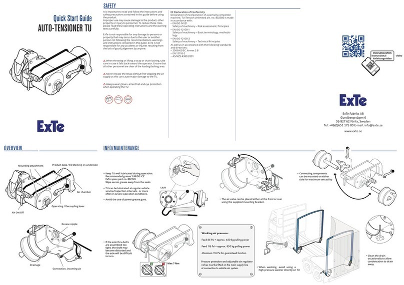
TU AUTO TENSIONER
Operating Instructions
Doc.no AD00002 Eng
ExTe Fabriks AB, BOX 18, SE-827 62 Färila, Sweden. Tel: +46 (0)651-175 00. E-mail: [email protected] www.exte.se
Item no.: AD00002 Eng REV_B © Copyright ExTe Fabriks AB, 2019

2www.exte.se
CONTENTS
Important information ................................................................................................4
Technical support ...............................................................................................................4
Spare parts ..........................................................................................................................4
Scrapping.............................................................................................................................4
Modication ........................................................................................................................4
Warranty ..............................................................................................................................4
Accessories..........................................................................................................................4
Contact information ...........................................................................................................4
Safety rules....................................................................................................................5
Selection of accessories.....................................................................................................5
Installation ..........................................................................................................................5
Operation ...........................................................................................................................5
Design and function .....................................................................................................6
General ................................................................................................................................6
Technical data .....................................................................................................................7
Dimensions and weight .....................................................................................................7
Recommended working pressure ....................................................................................7
Placing of TU........................................................................................................................7
Note......................................................................................................................................7
Operation.......................................................................................................................8
Lashing of load....................................................................................................................8
Release of sling ...................................................................................................................9
Maintenance................................................................................................................10
Recommended grease.................................................................................................... 10
Installation ..................................................................................................................11
Connecting compressed air ........................................................................................... 11
Airow diagram ............................................................................................................... 11
Fastening TU..................................................................................................................... 12
Mounts for bunk tting................................................................................................... 12
Brackets for body mounted winches ........................................................................... 13
Brackets for atbed mounted winches ........................................................................ 13

3
Installation of TU and strap guide ................................................................................. 14
Fitting the disengaging lever. ........................................................................................ 15
Installation of drum......................................................................................................... 15
Installation of chain......................................................................................................... 16
Installation of strap ......................................................................................................... 17
Anchoring the LASHing ..............................................................................................18
Long-life hook and holder ............................................................................................. 18
Anchoring the lashing ..................................................................................................... 18
Bunk-mounted quick-release......................................................................................... 19
Frame-mounted quick-release....................................................................................... 19
Flatbed quick-release ...................................................................................................... 19
Troubleshooting..........................................................................................................20
Problem ............................................................................................................................ 21
Cause................................................................................................................................. 21
Solution............................................................................................................................. 21
Spare parts ..................................................................................................................22
Front housing................................................................................................................... 22
Rear housing .................................................................................................................... 23
Declaration of Conformity.........................................................................................24
Label, LC and CE............................................................................................................... 24

4www.exte.se
Before you start using your ExTe product, it is impor-
tant that you read and understand the content of
these operating instructions, especially the sections
that describe Safety.
The operating instructions are primarily intended to
teach you about the product’s functions and prop-
erties and how to best use them. They also contain
important safety and maintenance information and
describe any problems that may occur during use.
Keep the operating instructions with the product,
as important information regarding use, safety and
maintenance may be required. It is also possible
to obtain information about our products through
our website on the internet. You can nd us at
www.exte.se.
All information, all images, illustrations and speci-
cations are based on the product information that
was available at the time of publication of these
operating instructions. Images and illustrations
found in the operating instructions are type exam-
ples and are not intended to be exact depictions of
dierent parts of the product.
ExTe reserves the right to make changes in design
without prior notice. We cannot be held responsible
for misprints and changes.
Technical support
If you need support or service, please contact in the
rst place the ExTe dealer in your area. You can also
contact ExTe’s technical support at
Tel +46 (0)651-175 30 or email support@exte.se
More information at www.exte.se/support
Spare parts
Only original ExTe spare parts should be used.
The use of other parts could invalidate the product
guarantee.
Scrapping
TU is manufactured from recyclable materials or
materials that can be reused. Specialist companies
handle worn out products, dismantle them and
recycle materials that can be reused.
Modication
Warranty
TU is supplied with a 1 year warranty or according
to the actual agreement. The warranty covers
functional faults, faulty material and manufacturing
faults that may arise during the guarantee period
during normal use.
The warranty does not cover:
• Normal wear.
• Faults caused by insucient maintenance.
• Faults caused by improper or negligent
operation.
Repairs under warranty shall be carried out
by ExTe Fabriks AB or by ExTe Fabriks AB’s con-
tracted partner.
Please refer to our website www.exte.se for more
information.
Accessories
TU has a number of accessories which make it
adaptable to most needs. Accessories are constantly
being developed; please see the current product
catalogue.
Contact information
ExTe Fabriks AB
Gundbergsvägen 6
Box 18
SE-827 62 Färila, Sweden
Tel: +46 (0)651-175 00
sales@exte.se
support@exte.se
m Warning!
Modication is not permitted. If the equipment
has been modied, the product guarantee will be
void. Risk of injury!
IMPORTANT INFORMATION

5
OperationIt is important to read and follow the instructions
and safety precautions contained in these operat-
ing instructions before using the product. Improper
use may cause damage to persons, the product and
other property. To reduce these risks, please read
these operating instructions and the warning texts
carefully. ExTe is not responsible for any damage to
persons or property that may occur due to the user
or another person not following the recommenda-
tions, warnings and instructions contained in these
operating instructions. ExTe is not responsible for
any accidents or injuries resulting from a lack of
good judgement by anyone.
Selection of accessories
There is a wide range of accessories for TU
Installation
mChoosing the right accessories is based on the
conditions that apply to each application. Choosing
the correct bracket, drum, strap, chain and other
accessories should be done in consultation with
your ExTe dealer.
SAFETY RULES
mThe screws that hold the drum should be tight-
ened gently. If the screws are too tight, the shaft
may become oval and the tensioner will operate
sluggishly.
Max 7 Nm
m Never release the strap without rst cutting
the air supply as this can cause major damage to
the TU.
mThe disengaging lever and drum should be
tted on opposite sides of the tensioner. This is to
avoid a loose strap being caught in the lever, which
can lead to unintended disengagement during
operation.
mWhen throwing or lifting a strap or chain sling,
take care in case the sling misses and comes back.
Ensure that only the person performing the lift/
throw is within range of the strap.
mAlways wear gloves, a helmet and eye protection
when handling the TU.
m Be careful not to get your hands, ngers or
clothing between the band/cable/chain and load
when operating the air valve.
m Ensure that no tools have been left on the ten-
sioner when disengaging or operating the air valve.
m
TU may only be used for the purpose for which
it is intended.

6www.exte.se
Air On / O
Operation / Disengaging
Main attachment Product data / CE marking
Cylinder
General
TU has been developed to secure cargo in dierent types of heavy goods transport, whether it is timber or
other freight that is transported. The tensioner is driven by compressed air but can be operated manually
if needed. Disengaging is done manually or in combination with TU remote control, which is available as an
accessory. With remote control, disengaging is done with the push of a button on a remote control, which is
especially suitable if the tensioner is dicult to access, under a atbed/box or similar. TU continues to tension
automatically and has unlimited tensioning length.
A chassis made of anodised aluminium and stainless steel plates is designed to withstand outside eects and
ensure that the tensioner will maintain its high nish for many years.
TU has been developed for high operating reliability with few moving parts, as well as minimal and easy main-
tenance. It can be equipped with dierent drums and other accessories as well as being tted with a variety of
brackets. We have here chosen to show the tensioner with a large drum with room for a 10 metre long, 50 mm
wide strap. But the handling of the tensioner and its functions is largely done in the same way regardless of the
accessories selected.
DESIGN AND FUNCTION
Connection, incoming air
Drainage
Grease nipple

7
123
36
133
12,8
(36)
145
200
408
123
36
133
12,8
(36)
145
200
408
Technical data
Dimensions and weight
Width ............................................... 200 mm
Length ............................................. 408 mm
Height .............................................. 145 mm
Weight ............................................. Approx. 11 kg
Recommended working pressure
*Supply 4.5 bar.....approx. 450 kg on lashing
*Maximum 8.0 bar for guaranteed function
Placing of TU
When driving timber, it is recommended that TU is
placed so that the sling ends up on the inside
of the timber bunks.
Note
Dierent mounting brackets allow xed or sliding
adjustment of tensioner positions to suit goods being
transported.

8www.exte.se
OPERATION
mAlways wear gloves, a helmet and
eye protection when handling the TU.
B
3
1
2
4
TU automatically continues
to tighten the sling
during transportation.
Lashing of load
1. Close the air supply valve;
the air chamber is relieved.
2. Disengage TU.
3. Pull out the sling. Place the sling
over the load in an appropriate way.
4. Secure the sling in an appropriate
way on the opposite side.
5. Turn the lever to operating position.
6. Tension the sling manually using
the turning handle on the drum.
7. Open the air supply valve.
8. The sling is rolled in and the load is
anchored. Secure any loose sling.
7
8
5
mWhen throwing or lifting a strap
or chain sling, take care in case
the sling misses and comes back.
Ensure that only the person
performing the lift/throw is
within range of the strap.
mBe careful not to get your hands,
ngers or clothing between the
band/cable/chain and load when
operating the air valve. Risk of injury.
mEnsure that no tools have
been left on the tensioner when
disengaging or operating the air
valve. Risk of injury.
A
6

9
11
9
10
mNever release the strap without
rst cutting the air supply as this
can cause major damage to the TU.
C
D
Release of sling
9. Close the air supply valve;
the air chamber is relieved.
10. Disengage TU.
11. Loosen the sling's far end.
12. Make sure that the lever is
in operating position.
13. Open the air supply valve.
14. The sling is rolled in.
Secure the loose end of the sling.
12
13
14

10 www.exte.se
Regularly check that the product is in good working
order and that all safety devices are intact. Any faults
discovered must be rectied before the product
isused.
TU has been developed for high operating reliability
with few moving parts, as well as minimal and easy
maintenance. Check regularly:
• that all hoses and couplings are airtight and
in good condition. Replace if necessary.
• that straps and chains are in good
condition. Replace if necessary.
• that drainage holes are open, to allow any
condensation to drain. Clean out if necessary.
mKeep TU well lubricated during operation.
L & R
m
mWhen washing, avoid using a high pressure
washer directly on TU.
mPrevent obstructions by operating the tensioner
empty from time to time.
MAINTENANCE
The (2) grease nipples are located on each side under
the drive shaft.
Regular visual inspections are recommended during
operation. Spray grease into the nipples until clean
grease comes out at the shaft. Wipe o excess grease.
Recommended grease
TU must be lubricated with CARGO ICE ExTe item
no. 802149, or grease with equivalent properties.
Synthetic complex grease with EP additives, NLGI 2.
Drop > 150°C Working temperature range minimum
-50° C to +140° C

11
Connecting compressed air
TU has a valve kit. The vehicle's pneumatic system is connected to the valve and is used to shut o the air
supply to ExTe TU before the tensioner is put into the disengaging position. The installation and placing of
the valve kit can vary and can be adapted to the user's requirements. The main valve kit, item no. 802301
can be used to regulate the air supply to several TU tensioners at the same time.
mNote!
Plan the placing of the valve kit and air hoses
carefully to avoid them getting too close to other
moving parts, such as the disengaging lever.
Secure hoses in an appropriate way. Valves
should be easily accessible.
INSTALLATION
Airow diagram
1. A pressure relief valve shall be placed well pro-
tected in the frame, before the rst tensioner.
2. A main valve shall be used that can shut o
the supply line to the tensioners. Can be t-
ted using a bulkhead opening in the frame.
3. For each TU, a separate air valve shall be tted
to the air line for operation of each tensioner.
Vehicle pressure tank
Pressure relief valve
Main valve (802301)
TU tensioners
Air valve
(802319)
1
2
3
Dierent placing of the air valve

12 www.exte.se
Mounts for bunk tting
TU is tted directly onto the bunk frame. The drum
holding the strap or the chain is placed alongside the
bunk for the best possible securing of the load.
Brackets for bunk mounting are available in dierent
versions depending on the series and the desired
function.
Spiral hoses are recommended for the compressed
air when mounting on moveable bunks.
Fastening TU
Brackets for installation of TU available for all ExTe's
timber bunk series and in various designs depending
on function. ExTe original brackets are well tested to
withstand the forces and loads required. TU is designed
so that the connections can be moved and turned
according to your wishes.
For further information about each conguration,
contact s[email protected]
INSTALLATION
m Always t TU with original ExTe brackets for
secure anchorage.
mIt is important is to follow the installation
instructions for each bracket to ensure safety
in operation.

13
Brackets for atbed mounted winches
Bracket for xed mounting in atbed body
Sliding bracket for moveable winch in atbed
body
Brackets for body mounted winches
Brackets mounted in the body without exibility
to move.
m Make sure that existing or modied structures
on the vehicle is engineered for sucient strength
for this form of mounting.

14 www.exte.se
INSTALLATION
mFollow the installation instructions supplied for
each bracket. If there are no instructions available,
these can be found at exte.se or contact ExTe.
Installation of TU and strap guide
Always t original ExTe brackets for secure anchorage.
Installation of any strap guide is done when installing
the tensioner.
The strap guide bracket is reversible for mounting on
the left or right side.
Fit the strap guide on its bracket. Tighten the screws
with a torque wrench.
Tightening torque: 25 Nm.
Ensure that the bracket is mounted so that the guide
is as close as possible to the outer side of the vehicle.
Fit the strap guide using the screw kit supplied.
Tighten the screws with a torque wrench.
Tightening torque: 80 Nm.

15
Fitting the disengaging lever.
The disengaging lever can be tted in six dierent
positions at intervals of 60 degrees to t existing
space. Tighten the screw with a torque wrench.
Tightening torque 25 Nm.
Installation of drum
In this example, a large 50 mm drum is being tted.
Other drums are tted in a similar way.
1. Run the drum shaft through the
tensioner drive shaft.
2. Secure the drum with the screw kit supplied.
3. Tighten the screws so that there is an extremely
small gap in the joint against the shaft.
mWarning!
The disengaging lever and drum shall be tted on
opposite sides of the tensioner. This is to avoid
a loose strap being caught in the lever, which
can lead to unintended disengagement during
operation.
mThe screws that hold the drum should be tight-
ened gently. If the screws are too tight, the shaft
may become oval and the tensioner will operate
sluggishly.
Max 7 Nm

16 www.exte.se
Installation of chain
Installation of short-link 6mm chain on drum.
1. Run the chain's two outermost links
through the drum's cross-shaped hole.
INSTALLATION
2. Turn the outermost link so it is at against
the drum, with one round of the link centred
over an appropriate corner of the hole.
3. Install with the supplied bolts, washers
and nuts through hole and link.
Tighten with a torque wrench.
Tightening torque 25 Nm.

17
Installation of strap
In this example, a 50 mm strap is being tted on
a large drum. Fitting of other straps is done in a
similar way.
1. Insert the strap between the shaft and
the stop bolt. If the stop bolt is loose,
tighten it with a torque wrench.
Tightening torque 50 Nm.
2. Place the locking pin in the strap loop.
mNote!
If the tensioner is equipped with strap guide, start
by pulling the strap through this.
3. Pull the strap back until it stops
the against the locking bolt.
4. Manually roll up all the strap on the drum
using the turning handle on the drum.
5. Secure the loose end of the strap in
the strap guide or, if there isn’t one,
in the vehicle's existing devices.

18 www.exte.se
Anchoring the lashing
The sling is anchored most easily with ExTe quick-releases. These are available with
both manual and automatic air-controlled function. With ExTe releases, the sling
is released from the same side as TU, making the work easy.
TU automatically continues to tighten the sling during transportation.
Long-life hook and holder
The long-life hook is mounted on the stanchion. Using
the crane grapple, the long-life hook is captured and
the sling is easily lifted over the load for anchoring.
ANCHORING THE LASHING
mWhen throwing or lifting a strap or chain sling,
take care in case the sling misses and comes back.
Ensure that only the person performing the lift/
throw is within range of the strap.

19
Bunk-mounted quick-release
Mounted in bracket for each bunkseries.
Manual disengagement with steel cable
running along the side of the frame
or automatic disengagement with
compressed air.
Frame-mounted quick-release
Mounted in the correct bracket in the
frame of the vehicle or rig. Manual
disengagement with steel cable via
a bushing in the frame or automatic
disengagement with compressed air.
Flatbed quick-release
This release is welded into the frame
structure of the atbed. The sling is
disengaged manually with a steel cable.

20 www.exte.se
TROUBLESHOOTING
This section contains a troubleshooting guide that describes a number
of errors and events that may arise when using your product as well
as suggestions for corrective action. You should always contact your
ExTe dealer or service contact in case of uncertainty.
Other manuals for TU
1
Table of contents
Other ExTe Automobile Accessories manuals