manuals.online logo
Brands
  1. Home
  2. •
  3. Brands
  4. •
  5. Detroit Speed
  6. •
  7. Automobile Accessories
  8. •
  9. Detroit Speed Selecta-Speed 121633 User manual

Detroit Speed Selecta-Speed 121633 User manual

DSE F501-300 (Rev 06/28/19) Page 1 of 15
Detroit Speed, Inc.
Selecta-Speed Wiper Kit
1973-83 C10 GM Truck
P/N: 121633 & 121634
A downpour of rain will no longer hinder your ability to clearly see the road. The Detroit Speed
Selecta-Speed Wiper Kit provides you with the performance and convenience of a late model
wiper system in a package that easily and cleanly mounts in your 1973-83 C10 GM Truck.
Figure 1 –PN 121634 Shown
Item #
Description
Quantity
1
Wiper Motor Assembly
1
2
Wiper Control Module w/Mounting Plate
1
3
Wiper Harness
1
4
Wiper Switch Assembly
1
5
Hardware Kit
1
6
Instructions
1
DSE F501-300 (Rev 06/28/19) Page 2 of 15
This kit features a seven speed wiper system with five delays, low speed, and high speed. The
new pitman arm, included in the kit, connects directly to your existing wiper linkage. A rotary
switch is also included, along with a complete wiring harness.
This kit does feature a washer pump option as the wiper switch does have a push button
function. The wiring harness/control module is equipped with a power and ground wire to install
an inline electric washer pump. Detroit Speed does offer a washer pump kit available as part
number 121102.
Hardware Kit Checklist –Detroit Speed 1973-83 C10 Wiper Kit
Part Number
Description
Quantity
Check
9312209
1973-74 C10 Hardware Bag
1
9312206
Wiper Switch Adapter Assembly
1
9912060
1-1/4” Firewall Grommet
1
9912244
Billet Aluminum Wiper Switch Knob
1
9912044
3/8” AN Stainless Steel Washer
1
950054FS
10-24 x 3/4”L Button Head Screw
3
980096FS
5/16”-18 x 1”L Hex Head Flange Bolt
1
970043FS
5/16” SAE Washer
1
960033FS
5/16”-18 Nylock Nut
1
9312212
1975-83 C10 Hardware Bag
1
9312210
Wiper Switch LED Light Box Assembly
1
9912365
Acrylic Wiper Cover Plate
1
9912367
LED Dimmer
1
9912364
Pre-Wired White LED
1
9912366
2-Wire Lever Terminal Block
4
9912060
1-1/4” Firewall Grommet
1
9912244
Billet Aluminum Wiper Switch Knob
1
950128FS
No. 8 x 5/8”L Sheet Metal Screw
2
950054FS
10-24 x 3/4”L Button Head Screw
3
980096FS
5/16”-18 x 1”L Hex Head Flange Bolt
1
970043FS
5/16” SAE Washer
1
960033FS
5/16”-18 Nylock Nut
1
Installation Instructions:
1. Before beginning, please ensure that the parts included with your kit match the parts list
above. Ensure that the factory wiper system is in its “Parked” position. Disconnect the
battery power by removing the negative battery lead from the battery.
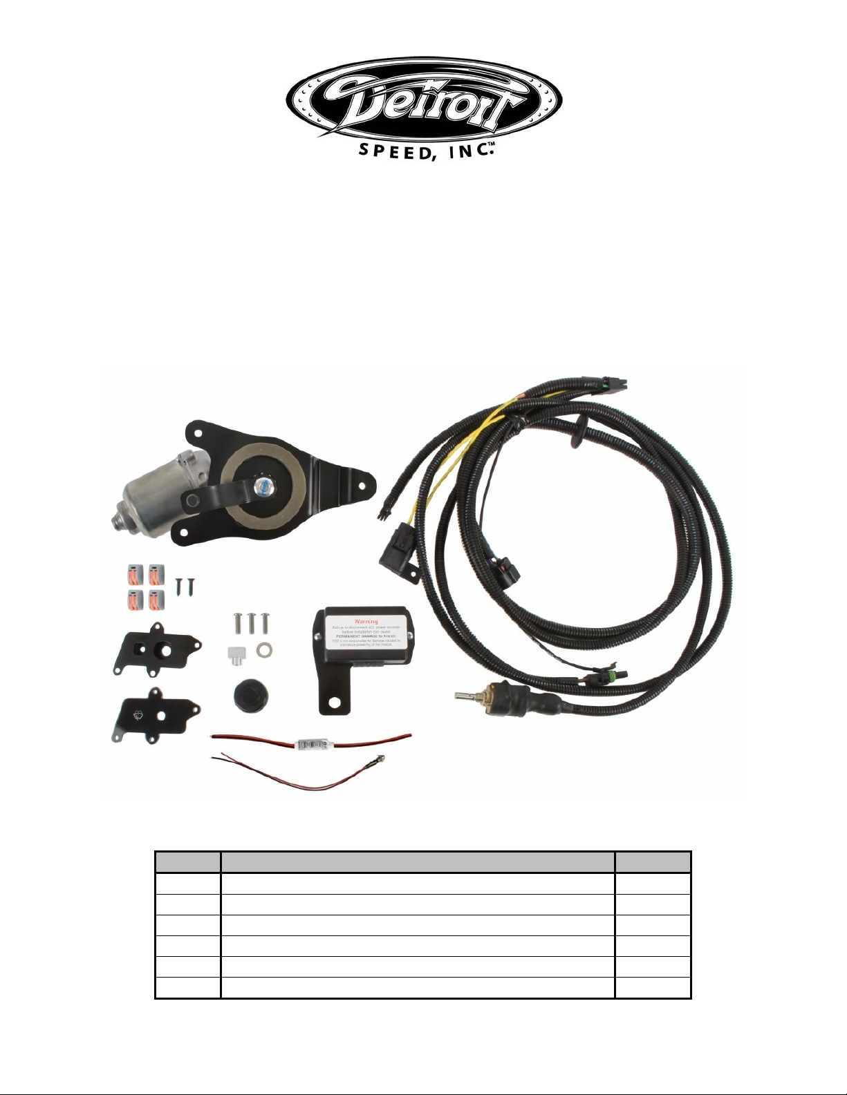
2. Mark the wiper arms’ parked location with masking tape for reference (Figure 2 on the next
page). It will be easier to access the wiper linkage with the wiper arms midway through their
travel.
DSE F501-300 (Rev 06/28/19) Page 3 of 15
Figure 2 –Parked Location
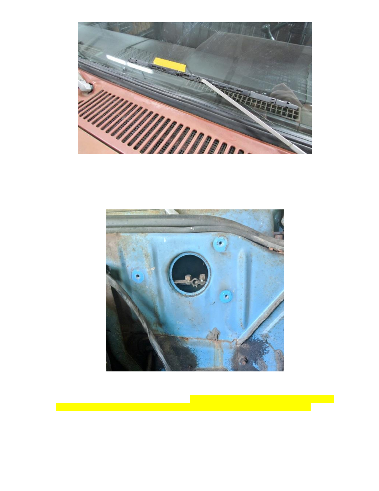
3. Remove the 3 bolts holding the stock wiper motor to the firewall.
4. Disconnect the wiper linkage from the wiper motor pitman arm and remove the stock wiper
motor from the firewall (Figure 3).
Figure 3 –Remove Stock Wiper Motor
5. The original wiring will not be used with the new Selecta-Speed Wiper Kit. A custom harness
is provided to replace the original harness. NOTE: If you decide to cut the old wires please
pay special attention to properly terminate the wire ends to avoid possible shorting.
6. Mount the new wiper motor assembly to the firewall. Use the three supplied 10-24 x 3/4”L
button head screws to mount the wiper motor assembly to the firewall. The adapter plate
will mount to the firewall using the original wiper motor firewall weld nuts (Figure 4 on the
next page).
DSE F501-300 (Rev 06/28/19) Page 4 of 15
Figure 4 –Attach Wiper Motor to Firewall
7. Attach the new pitman arm to the original wiper linkage. NOTE: The Selecta-Speed wiper kit
is shipped with the pitman arm in the “parked” postion. Do not move the pitman arm by hand
to attach the wiper linkage. If the pitman arm is moved from the original “parked” position
from Detroit Speed, it may result in the wiper blades stopping in the wrong spot on the
windshield.
8. The Selecta-Speed switch will replace the stock switch. Remove the screws holding the
gauge panel to the dash and remove. CAUTION: The gauge panel can flex a little, but on
certain trucks, it is necessary to remove the headlight knob first in order to remove the
gauge panel. Pull the headlight switch out as far as it will go. Press down on the release
button and pull out the headlight knob (Figure 5).
Figure 5 –Remove Headlight Knob
9. Remove the 2 screws holding the stock wiper switch to the dash (Figure 6 on the next page).
Disconnect the wiper switch connector from the back of the wiper switch and remove the
switch. For 1973-74 vehicles, tie up the original wiring under the dash and skip to Step 23.
For 1975-77 vehicles, proceed to the next step. For 1978-83 vehicles, skip to Step 11.
Push to
Remove Knob
DSE F501-300 (Rev 06/28/19) Page 5 of 15
Figure 6 –Remove Factory Wiper Switch (1973-74 shown)
10.Once the switch is removed from the dash, remove the light bulb housing by turning it
counter clock-wise in the switch housing. In order to use the LED light for the new wiper
switch, you will need to cut the wires from the original light bulb housing. Cut the gray
(positive) and black (ground) wires as close to the terminals as possible. Skip to Step 12.
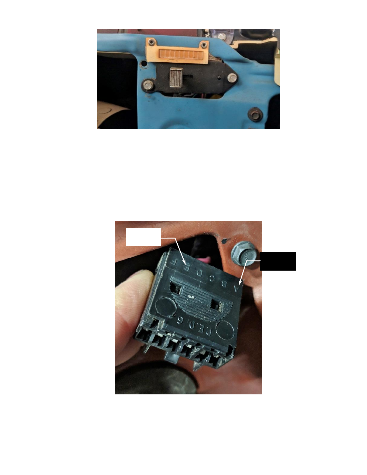
11.Once the wiper switch is removed from the dash, you will need to cut the “A” and “E” wires
from the back of the original wiper switch connector in order to use the LED light bulb (Figure
7). NOTE: The “A” wire is gray (positive) and the “E” wire is black (ground). Cut the wires as
close to the terminals as possible.
Figure 7 –Cut “A” & “E” Wires
12.Strip the wires in the vehicle that were cut for the light bulb, the wires on the provided
dimmer, and LED wires for the provided two-wire T-junction connector. Use the indicator on
the bottom of the T-junction connector to ensure that enough wire is stripped (Figure 8 on
the next page).
“E” – Black
Wire
“A” – Gray
Wire
DSE F501-300 (Rev 06/28/19) Page 6 of 15
Figure 8 –Strip Wires for Connector
13.Remove the nut on the provided LED and insert the LED through the square hole on the
front of the wiper switch LED light box assembly. Install the nut back onto the LED and tighten
with a 8mm wrench (Figure 9).
Figure 9 –Install LED into Light Box Assembly
14.Remove the star washer and hex nut from the new wiper switch. Install the wiper switch
through the back of the light box assembly. Make sure the anti-rotation tab on the wiper
switch locks into the anti-rotation hole on the light box assembly (Figure 10).
Figure 10 –Insert Wiper Switch into Light Box
15.Install the star washer and hex nut that was removed in the previous step and re-install it
onto the wiper switch. Tighten the wiper switch nut into the light box assembly using a 13mm
DSE F501-300 (Rev 06/28/19) Page 7 of 15
wrench (Figure 11). NOTE: Detroit Speed recommends using a zip tie to hold the LED wire
and the wiper switch together. This will help protect the small LED wires from getting
crushed, twisted, or bound up.
Figure 11 –Tighten Wiper Switch Assembly
16.Use the provided two-wire T-junction connector to safely connect the LED dimmer to the
original wires from the wiper switch bulb. Ensure that you are connecting the “5-24V” side
of the dimmer to the original truck wires. This is indicated on the label of the dimmer (Figure
12). Lift up the orange levers of the T-junction connectors. Using one of the connectors, feed
the gray wire from the original harness into one hole and the red wire from the dimmer into
the other hole until they bottom out. Using a second connector, feed the black wire from the
harness into one hole and the black wire from the dimmer into the other hole until they
bottom out. Close the orange levers to lock the wires in place. Gently pull to ensure that the
wires are locked in place. NOTE: Instead of using the connectors, you may solder and heat
shrink the wires together.
Figure 12 –Connect 5-24V side of LED Dimmer to Original Light Bulb Wires
17.Next, install another set of the T-junction connectors onto the other end of the LED dimmer
(Figure 13).
DSE F501-300 (Rev 06/28/19) Page 8 of 15
Figure 13 –Install Connectors to LED Dimmer
18.Ensure that you are connecting the “LED” side of the dimmer to the original wires. This is
indicated on the label of the dimmer. Insert the LED wires to the LED dimmer connectors
paying close attention to the wire colors. The black wire on the LED should connect to the
black wire on the dimmer and the red wire on the LED should connect to the red wire on the
dimmer (Figure 14). NOTE: Instead of using the connectors, you may solder and heat shrink
the wires together. Wiring the LED or dimmer backwards will not cause any damage. The
components simply will not work properly.
Figure 14 –Connect LED to Dimmer
DSE F501-300 (Rev 06/28/19) Page 9 of 15
19.Before the gauge panel is re-installed, you will need to set your LED brightness on your
dimmer. Make sure all electical connections are completed and re-connect the negative
battery lead to your battery. To set the dimmer, be sure that the dimmer is wired to the
original light circuit (red to gray, black to black). It may be helpful to set your dimmer in a
dark garage.
20. Place the provided acrylic wiper cover plate over the light box assembly and turn on the
truck headlights. If the wiper LED does not illuminate, hold the middle “Speed/☼/Power”
button until the wiper LED turns on. Press the “Light/☀” button to activate static mode. In
static mode, the middle “Speed/☼/Power” button will make the bulb dimmer. The
“Light/☀” button will make the bulb brighter (Figure 15). There are 10 different settings to
match the brightness to your other gauges. NOTE: If the LED does not illuminate or respond
to button presses, you may have one of the components wired backwards. Simply double
check your wiring and fix as needed. Also ensure that the small LED wires are not crushed,
twisted, or bound up.
Figure 15 –Three Buttons on LED Dimmer
21.The “Mode” button enters dynamic mode. This will cause the wiper LED to flash or flicker.
This function is likely not desired for your wiper LED. If you accidently enter this mode, hit
“Light/☀”. To confirm the correct settings, leave the wiper LED on and turn the truck lights
off and then back on. The wiper LED should now turn on with the truck lights and remember
the last setting.
22.Once you set the desired brightness, the dimmer will not require any further adjustment and
may be tucked behind the dash with the switch wiring (Figure 16). Once you have the LED
brightness set, disconnect the negative battery lead from the battery. NOTE: Take care in
tucking the wires behind the dash. Ensure that the small LED wires are not crushed, twisted,
or bound up as this could prevent the LED from working. Skip to Step 24.
DSE F501-300 (Rev 06/28/19) Page 10 of 15
Figure 16 –Set LED Brightness
23.Next, install the wiper switch adapter plate onto the Selecta-Speed wiper switch. Remove
the switch hex nut and star washer from the switch. Position the switch anti-rotation tab
into the anti-rotation hole located in the adapter plate (Figure 17). Hold the adapter plate to
the wiper switch by threading on the switch hex nut and provided 3/8” AN washer and
tighten.
Figure 17 –Install Switch Adapter Plate (1973-74 shown)
24.For the 1973-74 application, the original fasteners will be used to install the new switch
assembly into the dash (Figure 18). For the 1975-83 application, place the provided acrylic
wiper cover plate over the light box assembly. Use the provided No. 8 x 5/8” sheet metal
screws to install the new switch assembly into the dash using a 1/4” socket (Figure 19).
DSE F501-300 (Rev 06/28/19) Page 11 of 15
Figure 18 –Install Wiper Switch (1973-74) Figure 19 –Install Wiper Switch (1978-
83)
25.Re-install the gauge panel to the dash using the original fasteners. Slide the wiper knob onto
the shaft of the wiper switch. Align the set screw with the flat on the switch shaft and tighten
(Figure 20 & 21). NOTE: Make sure the set screw locks onto the flat on the switch shaft.
Figure 20 –Install Wiper Knob (1973-74) Figure 21 –Install Wiper Knob (1978-83)
26.Route the wiper motor connector side of the wiring harness (Figure 22) through the firewall
using an existing hole if possible. You can also drill a new hole in the firewall using a 1-1/4”
hole saw or Uni-Bit in order to allow the wiper motor connector to pass through the firewall.
NOTE: For 1975-83 vehicles, there is an existing grommet in the firewall that can be used
if opened up for the new wiper harness.
DSE F501-300 (Rev 06/28/19) Page 12 of 15
Figure 22 –Wiper Motor Connector
27.A rubber grommet is already installed on the wire loom from the wiper motor wires if
needed. Once there is enough of the loom through the firewall to connect the wiper motor,
move the grommet on the loom and install it into the firewall to seal the engine compartment
from the inside of the vehicle (Figure 23 on the next page).
Figure 23 –Install Wiper Motor Harness
28.The Detroit Speed Selecta-Speed harness does include a weather pack connector to install
an optional electric inline washer pump into your vehicle (Figure 24). Detroit Speed does
offer a washer pump kit you can purchase separately as part number 121102.
DSE F501-300 (Rev 06/28/19) Page 13 of 15
Figure 24 –Washer Pump Connection
29.If you do not want to use the washer pump feature, you can tie wrap this connector/loom
up under the dash. If you would like to use this option, use an existing hole or drill a new hole
in your firewall to pass the connector through the firewall. You will need a 1-1/8” diameter
hole in order to use the provided 1-1/4” rubber grommet. If you have purchased the Detroit
Speed washer pump kit, use the instructions from that kit to complete the washer pump kit
installation.
30.Next, you will need to install the wiper control module under the dash. It can be mounted
anywhere you prefer with the provided 5/16” bolt, washer & Nylock nut, however there is a
recommended location next to the kick panel, above the hood release.
31.Use a 1/2” socket to remove the bolt above the hood release. Remove the air vent for best
access to this bolt. Slide the module mounting plate in between the kick panel and the sheet
metal. Line up the hole in the mounting plate and the factory bolt hole. Re-install the original
bolt through the mounting plate and tighten (Figure 25).
DSE F501-300 (Rev 06/28/19) Page 14 of 15
Figure 25 –Mount Control Module
32.With the wiper control module in place, plug in the wiper switch and wiring harness
connectors into the control module (Figure 26).
Figure 26–Connect Wiper Switch & Harness to Module
33.Connect the yellow wire under the dash to a 12V ignition or accessory switched source.
(Circuit is active when the key is in the run postion). This lead is supplied with an inline 30
amp ATO fuse.
Wire
Harness
Wiper
Switch
Remove
Bolt
DSE F501-300 (Rev 06/28/19) Page 15 of 15
34.Connect the black wire with the round eyelet to a ground located under the dash. Make sure
a proper ground is obtained by removing any rust or paint from the metal.
35.Connect the negative battery lead and test the wiper system. Upon a successful test, the
wiper conversion is now complete. Secure the new wiring harness under the dash and in
the engine compartment. Re-install the cowl panel along with any other components that
had been removed.
NOTE: In some cases high energy ignition systems have caused interference with the
correct operation of the Selecta-Speed Wiper Kit due to spark plug wires routed closely to
the wiper motor. If this occurs, re-routing your spark plug wires may be neccesary.
If you have any questions before or during the installation of this product please contact
Detroit Speed Inc. at [email protected] or 704.662.3272
Legal Disclaimer:
Detroit Speed, Inc. is not liable for personal, property, legal, or financial damages from the use or misuse of
any product we sell. The purchaser is solely responsible for the safety and performance of these products. No warranty is
expressed or implied.

This manual suits for next models

1

Popular Automobile Accessories manuals by other brands

Carefree PARAMOUNT Service manual

Carefree

Carefree PARAMOUNT Service manual

Dakota Digital LED Tail Lights for 1971 Bel Air LAT-NR390 installation instructions

Dakota Digital

Dakota Digital LED Tail Lights for 1971 Bel Air LAT-NR390 installation instructions

Rightline Gear 100K40 quick guide

Rightline Gear

Rightline Gear 100K40 quick guide

TigerTough Group 72129 installation guide

TigerTough Group

TigerTough Group 72129 installation guide

Bundutec BUNDUANNEX owner's manual

Bundutec

Bundutec BUNDUANNEX owner's manual

Whelen Engineering Company 400 Series installation guide

Whelen Engineering Company

Whelen Engineering Company 400 Series installation guide

Cruz W 40 Assembly instructions

Cruz

Cruz W 40 Assembly instructions

Rydeen MV311S owner's manual

Rydeen

Rydeen MV311S owner's manual

DV8 OFFROAD SRBR-03 installation manual

DV8 OFFROAD

DV8 OFFROAD SRBR-03 installation manual

Parksafe Automotive CAMINTER15 manual

Parksafe Automotive

Parksafe Automotive CAMINTER15 manual

Federal Signal Corporation Commander 371LED-120B Installation and maintenance manual

Federal Signal Corporation

Federal Signal Corporation Commander 371LED-120B Installation and maintenance manual

Juice me 3 manual

Juice

Juice me 3 manual

GReddy Turbo Kit installation manual

GReddy

GReddy Turbo Kit installation manual

Mongoose M15 user guide

Mongoose

Mongoose M15 user guide

Beringer AEROTEC RADIAL Assembly instructions

Beringer

Beringer AEROTEC RADIAL Assembly instructions

Discount Car Stereo A2DIY-MBCD quick start

Discount Car Stereo

Discount Car Stereo A2DIY-MBCD quick start

Offroad Animal RB-JWR-JK-07-ASM0 Fitting instructions

Offroad Animal

Offroad Animal RB-JWR-JK-07-ASM0 Fitting instructions

Whispbar K560W Fitting Instructions for Basic Carrier

Whispbar

Whispbar K560W Fitting Instructions for Basic Carrier

manuals.online logo
manuals.online logoBrands
  • About & Mission
  • Contact us
  • Privacy Policy
  • Terms and Conditions

Copyright 2025 Manuals.Online. All Rights Reserved.