NL
Controleer de algemene goede staat van uw hek (geleiders, steunen die
de te schroeven en bewegende elementen van de automatische deuropening kun-
nen dragen). Het hek moet eenvoudig met de hand bewogen kunnen worden
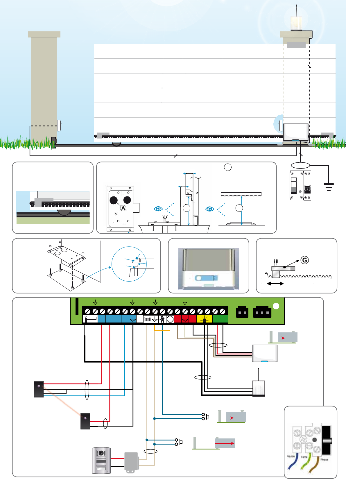
Fig. 1: Voorbereidende werkzaamheden voor de elektrische installatie
(handleiding blz. 10)
Fig. 2: Plaatsing van de tandheugels op het basisframe van het hek
(handleiding blz. 10)
Fig. 3: Plaatsing van de betonnen grondplaat (handleiding blz. 11)
Fig. 4 :Bevestig de steun op de betonnen grondplaat (handleiding blz. 11)
Fig. 5 :Bevestig het motorblok op de steun
Fig. 6 :Breng de aanslagen aan (handleiding blz. 12)
Fig. 7: Elektrische aansluiting (handleiding blz.14-15)
Fig. 8: Aansluiting op het elektrische netwerk (handleiding blz.15 en 10)
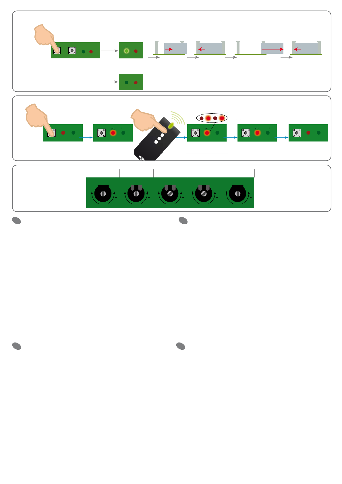
Fig. 9: Auto-learn proces van de slagtijden (handleiding blz.16)
• P1/Set gedurende 3s
Fig. 10: Auto-learn proces van de afstandsbedieningen (handleiding blz. 17)
• P2/Radio gedurende 2 s •druk op de afstandsbediening •LD2 knippert.
Fig. 11: Afstellingen voor een optimale werking van de automatische deuropening
(handleiding blz. 17)
LED:Afstelling schemerstand van de achtergrondverlichting
FOR: Kracht
PAU: Pauzetijd tijdens de stand automatische sluiting
OBS: Reactietijd bij obstakels (bij winderige zone bijvoorbeeld)
OVL: Detectie van obstakels. Gevoeligheid
GB
Check that your gate is in generally good condition (slide rails and sup-
ports allow movement with the automatic control elements attached).
This movement should be done easily when operated manually.
Fig. 1: Electrical installation preparation (instructions p.10)
Fig. 2: Positioning of the rack on the basic structure of the gate (instructions p.10)
Fig. 3: Positioning of the concrete base (instructions p.11)
Fig. 4: Fix the support on the concrete base (instructions p.11)
Fig. 5: Fix the motor block on the support
Fig. 6: Place the stops (instructions p.12)
Fig. 7: Electrical connection (instructions p.14-15)
Fig. 8: Connection to the electrical network (instructions p.15 et 10)
Fig. 9: Automatic practice runtime (instructions p.16)
• P1/Set during 3s
Fig. 10: Practice run using the remote controls (instructions p.17)
• P2/Radio during 2s •press the remote control •LD2 flashes.
Fig. 11: Adjustments to optimise the operation of your automatic controls
(instructions p.17)
LED:Adjustment of the backlight’s sensitivity to ambient lighting
FOR: Force
PAU: Set pause time during automatic closure mode
OBS: Reaction time on the obstacle (e.g. for windy areas)
OVL: Obstacle detection. Sensitivity
D
Überprüfen Sie den allgemeinen guten Zustand Ihres Tors (Schienen, die
Baueteile, die die Elemente der angeschraubten und sich bewegenden automati-
sierten Betriebseinheit aufnehmen können)
Es muss leicht beweglich sein, wenn es von Hand betätigt wird.
Fig. 1: Vorbereitung der elektrischen Installation (Broschüre S. 10)
Fig. 2: Positionierung der Zahnstangen auf der Grundstruktur desTors
(Broschüre S. 10)
Fig. 3: Positionierung des Betonsockels (Broschüre S. 11)
Fig. 4 :Befestigen Sie die Halterung auf dem Betonsockel (Broschüre S. 11)
Fig. 5 :Befestigen Sie den Motorblock auf der Halterung
Fig. 6 :Platzieren Sie die Anschläge (Broschüre S. 12)
Fig. 7: Elektrischer Anschluss (Broschüre S. 14-15)
Fig. 8: Anschluss an das Stromnetz (Broschüre S. 15 und 10)
Fig. 9: Eigenstudium der Bewegungszeiten (Broschüre S.16)
• P1/Set 3s
Fig. 10: Erlernen der Funktionsweise der Fernbedienungen (Broschüre S.17)
• P2/Radio 2 s •lang auf der Fernbedienung drücken •LD2 blinkt auf.
Fig. 11: Einstellungen zur Funktionsoptimisierung Ihrer automatisierten
Betriebseinheit (Broschüre S. 17)
LED : Dämmerregulierung der Rückleuchten
FOR : Kraft
PAU : Pausenzeitfenster bei dem automatischen Schließmodus
OBS : Reaktionszeit bei Hindernis (beispielsweise inWind ausgesetzten Gebieten)
OVL : Hindernisdetektion. Sensibilität
SK
Skontrolujte, či je brána všeobecne v dobrom stave (posuvné koľajnice a
podpory umožňujú pohyb pripojených prvkov automatického riadenia).
Tento pohyb by sa mal pri ručnej obsluhe vykonávať ľahko.
Fig. 1: Príprava elektrickej inštalácie (pokyny na str 10)
Fig. 2: Umiestnenie koľajnice do základnej konštrukcie brány (pokyny na str 10)
Fig. 3: Umiestnenie betónových základov (pokyny na str 11)
Fig. 4 :Podporu upevníte k betónovým základom (pokyny na str 11)
Fig. 5 :Motor umiestnite na nosník
Fig. 6 :Umiestnite zastavenia (pokyny na str 12)
Fig. 7: Elektrické zapojenie (pokyny na str 14-15)
Fig. 8: Pripojenie k elektrickej sieti (pokyny na str 15 a 10)
Fig. 9: Automatické cvičné spustenie (pokyny na str 16)
• P1/Set 3s
Fig. 10: Spustenie diaľkovým ovládačom (pokyny na str 17)
• P2/Radio 2 s •stlačte diaľkový ovládač •LD2 bliká.
Fig. 11: Nastavenie za účelom optimalizácie riadenie automatického ovládania
(pokyny str. 17)
LED : Nastavenie citlivosti podsvietenia na okolité svetlo
FOR : Vynútiť
PAU : Nastavenie pauzy počas režimu automatického zatvárania
OBS : Reakčná doba na prekážku (napr. vo veterných oblastiach)
OVL : Detekcia prekážky. Citlivosť
CS
Zkontrolujte, zda je brána obecně v dobrém stavu (posuvné kolejnice a
podpory umožňují pohyb připojených prvků automatického řízení).
Tento pohyb by se měl při ruční obsluze provádět lehce.
Fig. 1: Příprava elektrické instalace (pokyny na str. 10)
Fig. 2: Umístění kolejnice do základní konstrukce brány (pokyny na str. 10)
Fig. 3: Umístění betonových základů (pokyny na str. 11)
Fig. 4 :Podporu upevněte k betonovým základům (pokyny na str. 11)
Fig. 5 :Motor umístěte na nosník
Fig. 6 :Umístěte zastavení (pokyny na str. 12)
Fig. 7: Elektrické zapojení (pokyny na str. 14-15)
Fig. 8: Připojení k elektrické síti (pokyny na str. 15 a 10)
Fig. 9: Automatické cvičné spuštěn (pokyny na str. 16)
• P1/Set 3s
Fig. 10: Spuštění dálkovým ovladačem (pokyny na str. 17)
• P2/Radio 2 s •stiskněte dálkový ovladač •LD2 bliká.
Fig. 11: Nastavení za účelem optimalizace řízení automatického ovládání
(pokyny str. 17)
LED : Kontrolka LED Nastavení citlivosti podsvícení na okolní světlo
FOR : Vynutit
PAU : Nastavení pauzy během režimu automatického zavírání
OBS : Reakční doba na překážku (např. ve větrných oblastech)
OVL : Detekce překážky. Citlivost
PL
Należy sprawdzić ogólny stan bramy (szyny, podzespoły obejmujące ele-
menty przykręconej i ruchomej, zautomatyzowanej jednostki).
Brama musi dać się lekko przesuwać ręką.
Fig. 1: Przygotowanie instalacji elektrycznej (broszura, str. 10)
Fig. 2: Ustawienie listew zębatych na podstawowej strukturze bramy
(broszura str. 10)
Fig. 3: Ustawienie betonowej podstawy (broszura, str. 11)
Fig. 4 :Mocowanie uchwytu na betonowej podstawie (broszura, str. 11)
Fig. 5 :Mocowanie korpusu silnika w uchwycie
Fig. 6 :Ustawienie odbojników (broszura, str. 12)
Fig. 7: Przyłącze elektryczne (broszura, str. 14–15)
Fig. 8: Podłączenie do sieci elektrycznej (broszura, str. 15 i 10)
Fig. 9: Autotest czasów ruchu (broszura, str.16)
• P1/Set 3s
Fig. 10: Nauka obsługi pilotów zdalnego sterowania (broszura, str.17)
• P2/Radio 2 s •Nacisnąć przycisk na pilocie zdalnego sterowania
•Zamiga lampka LD2.
Fig. 11: Ustawienie optymalizujące działanie zautomatyzowanej jednostki
(broszura, str. 17)
LED : Regulacja wygaszania tylnych świateł
FOR : Siła
PAU : Przedział czasowy przerwy w przypadku automatycznego
trybu zamykania
OBS : Czas reakcji na przeszkodę (na przykład obszary narażone na wiatr)
OVL : Wykrywanie przeszkody. Czułość.
Notice intégrale sur le CD fourni ou à télécharger sur :
Istruzioni integrale sul CD fornito o a trasferire su:
Instrucciones íntegro sobre el CD proporcionado o a cargar a distancia sobre:
Manual integral sobre o CD fornecido ou fazer o download sobre:
Integral manual on provided CD or to download on:
Volledige korte kleurenhandleiding op geleverd CD of om te downloaden op:
Integrale Gebrauchsanweisung auf CD geliefertem oder zu laden auf : www.cfi-extel.com
• France : Hotline :
0 892 350 069 (0,337€TTC/min)
• Italia :Assistenza Tecnica : +39 02 96488273
assistenza@cfi-extel.com
• España :Asistencia técnica : 902 109 819
sat-hotline@cfi-extel.com
• Portugal : Serviço de apoio ao cliente :
707 201 138
Découvrez nos produits sur : www.cfi-extel.com, & .