Connect the AC power cord to the back of the switch, and
then plug the other end of the cord into an AC power outlet.
Warning: You must use a power cord set approved for the
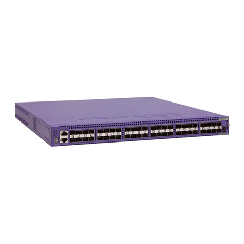
ERS 3600 Series switch and the power receptacle type for
your country.
a. Connect the console cable from the terminal to the console
port of the switch to allow initial configuration. Any terminal
or PC with the appropriate terminal emulator can be used
as the management station.
To connect to the switch
console port, you require a
console cable with an RJ-45
connector to match the
console port on the switch.
CLI Quickstart welcome screen
################################################################
Welcome to the ERS3600 setup utility.
You will be requested to provide the switch basic connectivity
settings. After entering the requested info, the configuration
will be applied and stored into the switch NVRAM.
Once the basic connectivity settings are applied, additional
configuration can be done using the available management inter-
faces.
Use Ctrl+C to abort the configuration at any time.
################################################################
Please provide the Quick Start VLAN <1-4094> [1]:
Please provide the in-band IP Address[192.0.2.3]:
Please provide the in-band sub-net mask[255.255.255.0]:
Please provide the Default Gateway[192.0.2.4]:
Please provide the Read-Only Community String[**********]:
Please provide the Read-Write Community String[**********]:
Please provide the in-band IPV6 Address/Prefix_length[::/0]:
Please provide the in-band IPV6 Default Gateway[::]:
################################################################
Basic stack parameters have now been configured and saved.
################################################################
1. Connect a Laptop/PC to any Ethernet port and ensure that
the PC has an IP address configured within the same IP
subnet as the switch management IP address.
2. Start your web browser, such as Internet Explorer or Firefox.
3. Enter switch management IP address in the URL field and
press Enter (for example; 192.0.2.1).
4. The switch summary screen appears on your browser. Use
the navigation tree on the left to select switch configuration
options.
Note: You do not need login credentials.
CLI boot and factory default commands:
boot – reboot the switch
boot default – reboot and use the factory default
configuration
restore factory default – reset the switch to factory
default configuration
The console port is the RJ-45 port shown with a blue border
outline on the front of your ERS 3600 Series switch (note the
orientation). The port is labeled Console.
Use an RJ-45 to DB-9 cable to connect the switch console
port to your management terminal. Extreme Networks
recommends that you use the RJ-45 Console Cable part
number: AL2011022-E6. Alternatively, a DB-9 to RJ-45
adapter or other suitable console cables can be used – the
maximum length of a console cable is 25 feet (8.3 meters).
The following table describes the RJ-45 console port pin-out
information. You can use the pin-out information to verify or
create a console cable for use with your maintenance
terminal.
Recommended reading
To obtain additional documentation references, go to
http://www.extremenetworks.com/support/documentation/
and download the following ERS 3600 documents:
• Locating Documentation
• Documentation Reference
• Installing ERS 3600
• Installation Job Aid
• Release Notes
3. Connect stacking cables as required for a Cascade Up (stack up)
or Cascade Down (stack down) configuration as shown below:
Cascade Down (stack down) configuration
1 = Base unit
2 = Cascade/Stack Cable
3 = Cascade/Stack Cable
(Return cable to make
stack resilient. Use longer
stack cable if required.)
4 = Last unit
4
2
3
1
Cascade Up (stack up) configuration
1 = Base unit
2 = Cascade/Stack Cable
3 = Cascade/Stack Cable
(Return cable to make
stack resilient. Use longer
stack cable if required.)
4 = Last unit
4
2
3
1
Check the front-panel LEDs as the device powers on to be
sure the PWR LED is lit. If not, check if the power cord is
plugged in correctly.
The ERS 3600 Series switches begin switching data after
the switch is powered up and has loaded the agent code
software, which is indicated by both the PWR and Status
LEDs being lit solid green.
Connector Pin Number Signal
1
2
3
4
5
6
7
8
RTS (ready to send) – optional
DTR (data terminal ready) – optional
TXD (transmit data) – mandatory
GND (ground) – mandatory
DCD (carrier detect) – optional
RXD (receive data) – mandatory
DSR (data set ready) – optional
CTS (clear to send) – optional
b. Set the terminal protocol on the terminal or terminal
emulation program to VT100 or VT100/ANSI.
c. Connect to the switch using the terminal or terminal
emulation application.
d. The Extreme Networks switch banner appears when you
connect to the switch through the Console port. There is no
default password for the switch for CLI console access.
Enter Ctrl+Y and type the following CLI commands:
• enable
• install
e. The CLI Quickstart welcome screen helps you enter the
information requested at each prompt.
Note: The ERS 3600 uses the default IP address of
192.168.1.1/24 if the switch does not get its IP address from
another source.
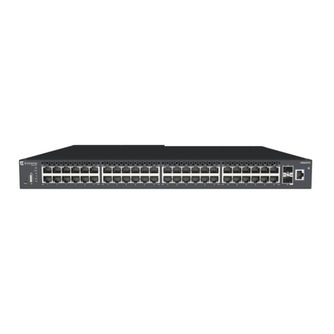
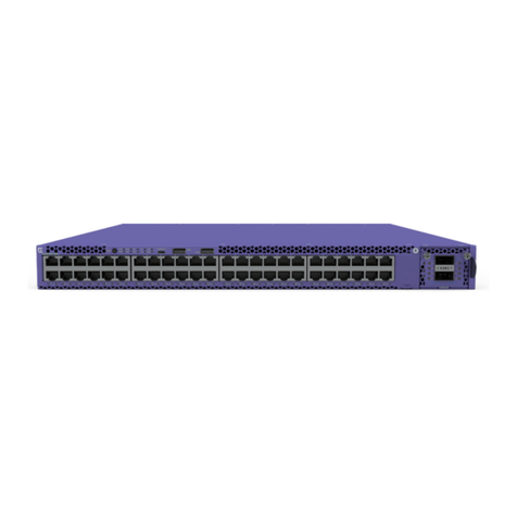
ERS3626GTS/ERS3626GTS-PWR+ ERS3650GTS/ERS3650GTS-PWR+
5Powering Up
6
7Console Port pin assignments
8Setting IP parameters using the console
port and CLI QuickStart
9Connecting to the ERS 3600 embedded Web UI
6480 Via Del Oro
San Jose, CA 95119
Tel: +1 408-579-2800
Toll-free: +1 888-257-3000
WWW.EXTREMENETWORKS.COM
Poster part number: 700513176 Rev.02
NN47213-300 02.03
