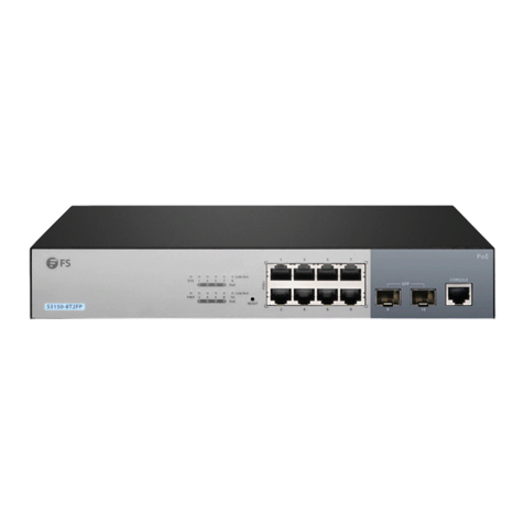
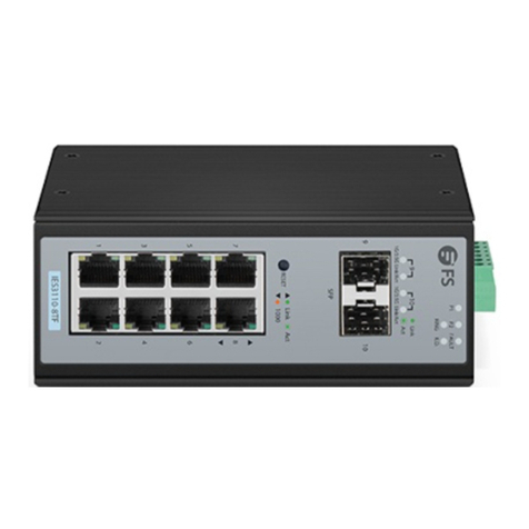
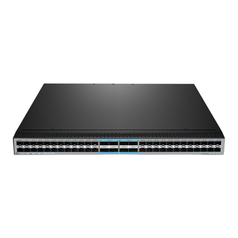
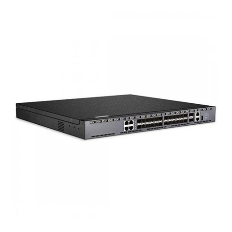
FS IES3100-8T4F-P User manual

L2+ MANAGED INDUSTRIAL SWITCH
SWITCH INDUSTRIEL MANAGEABLE L2+
IES3100-8T4F-P
Quick Start Guide V1.0
Quick Start Anleitung
Guide de Démarrage Rapide
PWR1
48-57V DC
PWR2
11
8
12
IES3100-8T4F-P PoE+
CLI

IES3100-8T4F-P PoE+
11
8
12
CLI
EN
1
Introduction
Accessory
Thank you for choosing IES3100-8T4F-P L2+ Managed Industrial Switch. This guide is designed to
familiarize you with the layout of the switch and describes how to deploy it in your network.
IES3100-8T4F-P
Console Cable x1
NOTE: IES3100-8T4F-P switch is equipped with dust plugs.

EN
2
Hardware Overview
Ports Description
SFP
RJ45
SFP port for 1G connection
CLI An RJ45 console port for serial management
10/100/1000BASE-T ports for Ethernet connection
Front Panel Ports
IES3100-8T4F-P PoE+
11
8
12
CLI
RJ45
SFP
CLI
IES3100-8T4F-P PoE+
11
8
12
CLI
RJ45
SFP SYS
PWR
Front Panel LEDs

EN
3
DescriptionLEDs
PWR
State
On
On
On
On
Blinking
Off
Off
Off
Off
Off
Yellow. PoE
Green: Link/Act
Blinking
Blinking
Power is being supplied to power input.
Power is not being supplied to power input.
The system is ready for operation.
No supply voltage or the system is not ready for
operation.
A PoE terminal device is connected and
receiving power via PoE.
No PoE port is available or power over
Ethernet function is disabled.
The port is linked.
The port is linked.
The port is transmitting the data.
The port is not linked.
SYS
RJ45
SFP
Upper Panel
PWR1
48-57V DC
PWR2
Grounding Point Terminal Block Connector

EN
4
Back Panel
DIN Rail Mounting Clip
NOTE: It is recommended to use Internet Explorer 8.0 or above to access the switch. If the
web interface of the Industrial Managed Switch is not accessible, please turn off the
anti-virus software or firewall and then try it again.
Installation Requirements
Before you begin the installation, make sure that you have the following:
Workstations running Windows XP/2003/2008/Vista/7/8/10, MAC OS X or later, Linux, UNIX, or
other platforms compatible with TCP/IP protocols.
Workstations are installed with Ethernet NIC (Network Interface Card).
Serial Port Connection (Terminal)
The above Workstations come with COM Port (DB9) or USB-to-RS232 converter.
The above Workstations have been installed with a terminal emulator, such as HyperTerminal
included in Windows XP/2003.
Serial cable -- one end is attached to the RS232 serial port, while the other ends to the RJ45 console
port of the switch.
Ethernet Port Connection
Network cables -- Use standard network (UTP) cables with RJ45 connectors.
The above PC is installed with Web browser.

EN
5
1. Grip the top of the DIN rail mounting clip onto the edge of the DIN rail.
2. Press the bottom of the clip onto the other side of the DIN rail.
3. Push the bottom of the clip outwards to remove it easily.
Mounting the Switch
DIN-Rail Mounting
Mounting the unit Releasing the unit
1. Connect one end of the grounding cable to a proper earth ground.
2. Secure the grounding lug to the grounding point on the switch upper panel with the screw and
washers.
Grounding the Switch
PWR1
48-57V DC
PWR2
PWR1
48-57V DC
PWR2

EN
6
Connecting the SFP Ports
1. Connect an Ethernet cable to the RJ45 port of a camera, outdoor AP, computer or another network
device.
2. Connect the other end of the Ethernet cable to the RJ45 port of the switch.
Connecting the RJ45 Ports
PWR1
48-57V DC
PWR2
11
8
12
IES3100-8T4F-P PoE+
CLI
PWR1
48-57V DC
PWR2
11
8
12
IES3100-8T4F-P PoE+
CLI
CAUTION: The earth connection must not be removed unless all supply connections have
been disconnected.
1. Remove the dust plugs first.

EN
7
Connecting the Console (CLI) Port
1. Insert the RJ45 connector into the RJ45 console port on the front of the switch.
2. Connect the DB9 female connector of the console cable to the serial port on the computer.
The upper panel of the switch indicates a DC inlet power socket and consists of one terminal block
connector within 5 contacts. Please follow the steps below to insert the power wire.
Connecting the Power
PWR1
48-57V DC
PWR2
PWR1
48-57V DC
PWR2
2. Plug the compatible SFP transceiver into the SFP port.
3. Connect a fiber optic cable to the fiber transceiver. Then connect the other end of the cable to
another fiber device.
PWR1
48-57V DC
PWR2
11
8
12
IES3100-8T4F-P PoE+
CLI

EN
8
Single DC (48-57VDC) Input
1. Insert positive/negative DC power wires into Contacts 1 and 2 for PWR1.
2. Tighten the wire-clamp screws for preventing the wires from loosening.
Dual Redundant DC (48-57VDC) Input
1. Insert positive/negative DC power wires into Contacts 1 and 2 for PWR1 and Contacts 5 and 4 for
PWR2.
2. Tighten the wire-clamp screws for preventing the wires from loosening.
Positive
Negative
Requiring good ground connection
NameNo. Description
+1
2
3
1
V1+ V1-
PWR1 PWR2
V2- V2+
2 3 4 5
1
V1+ V1-
PWR1 PWR2
V2- V2+
2 3 4 5

EN
9
NOTE: The wire gauge for the terminal block should be in the range from 12 to 16 AWG.
Pin 2 / 4
Positive (+) Pin Negative (-) Pin
Pin 1 / 5
Step1: Connect a computer to the console port of the switch with the console cable.
Step2: Start the terminal simulation software, such as HyperTerminal on the computer.
Step3: Set the parameters of the HyperTerminal: Baud rate to 115200, Data bits to 8, Parity to None,
Stop bits to 1.
Configuring the Switch
Configuring the Switch Using the Console Port
x
Quick Connect
Protocol: Serial
Flow Control
DTR/DSR
RTS/CTS
XON/XOFF
Save sessionShow quick connect on startup
The port may be manually entered or selected from the list.
Open in a tab
Cancel
COM3
115200
8
None
1
Port:
Baud rate:
Data bits:
Parity:
Stop bits:
Name of pipe:
Connect
Step4: After setting the parameters, click Connect to enter.

EN
10
Step 1: Connect a computer to the management port of the switch using the network cable.
Step 2: Set the IP address of the computer to 192.168.1.x ("x" is any number from 2 to 254).
Step 3: Open a browser, type http://192.168.1.1 and enter the default username and password,
admin/admin.
Configuring the Switch Using the Web-Based Interface
IE 8/9/10/11, Google Chrome, Firefox are supported
Login
admin
*****
?x
OK Cancel
General
IP address:
Subnet mask:
Default gateway:
You can get IP settings assigned automatically if your network
supports this capability. Otherwise, you need to ask your network
administrator for the appropriate IP settings.
Internet Protocol Version 4(TCP/IPv4) Properties
Use the following IP address:
Obtain an IP address automatically
Preferred DNS server:
Alternate DNS server:
Validate settings upon exit Advanced...
. . . 21168192
0255
255255
. . .
. . .
. . .
. . .
Obtain DNS server address automatically
Use the following DNS server addresses:
Step 4: Click Login to display the web-based configuration page.

EN
11
Troubleshooting
100M/1G Port Is Not Working
1. Ensure the optical module and cable have no problem.
2. Check if the configuration at both ends of the communication device is auto or forced rate
1. Test network connectivity through ping.
2. If the network is reachable, try restarting the switch.
3. Check if the corresponding service is enabled.
Connecting the Switch Remotely Unsuccessfully
1. Ensure the switch ports are in the no shutdown state.
2. Check if the switch can read the DDM information.
3. Check if the port speed setting is correct.
4. Try looping the switch cable.
The Port Is Not Working, the LED Indicator Is Off
1. Replace the twisted pair cable.
2. Check if the port configuration has the common working mode with the connected switch.
RJ45 Port Is Not in Connectivity or It Is Erroneous in Receiving/ Transmit-
ting Frames

EN
12
FS ensures our customers that for any damage or faulty items due to our workmanship, we will offer a
free return within 30 days from the day you receive your goods. This excludes any custom-made items
or tailored solutions.
Return: If you want to return the item(s), information on how to return can be found at
https://www.fs.com/policies/day_return_policy.html
Warranty: IES3100-8T4F-P switch enjoys a 5-year limited warranty against defects in
materials or workmanship. For more details about the warranty, please check at
https://www.fs.com/policies/warranty.html
5
Product Warranty
Online Resources
Download
Help Center
Contact Us
https://www.fs.com/products_support.html
https://www.fs.com/service/fs_support.html
https://www.fs.com/contact_us.html

13
DE
IES3100-8T4F-P PoE+
11
8
12
CLI
Einführung
Zubehör
Vielen Dank, dass Sie sich für den IES3100-8T4F-P L2+ Managed Industrial Switch entschieden haben.
Diese Anleitung soll Sie mit dem Aufbau des Switches vertraut machen und beschreibt, wie Sie ihn in
Ihrem Netzwerk einsetzen können.
IES3100-8T4F-P
Console-Kabel x1
HINWEIS: Der IES3100-8T4F-P Switch ist mit Staubschutzkappen ausgestattet.

14
DE
Hardware-Übersicht
Port Beschreibung
SFP
RJ45
SFP-Port für 1G-Verbindung
CLI Ein RJ45 Console-Port für die serielle Verwaltung
10/100/1000BASE-T-Ports für Ethernet-Verbindung
Ports an der Vorderseite
LEDs an der Vorderseite
IES3100-8T4F-P PoE+
11
8
12
CLI
RJ45
SFP
CLI
IES3100-8T4F-P PoE+
11
8
12
CLI
RJ45
SFP SYS
PWR

15
DE
BeschreibungLED
PWR
Status
An
An
An
An
Blinkt
Aus
Aus
Aus
Aus
Aus
Gelb: PoE
Grün: Link/Act
Blinkt
Blinkt
Der Netzeingang wird mit Strom versorgt.
Der Netzeingang wird nicht mit Strom versorgt.
Das System ist betriebsbereit.
Keine Versorgungsspannung oder das System ist
nicht betriebsbereit.
Ein PoE-Endgerät ist angeschlossen und
wird über PoE mit Strom versorgt.
Es ist kein PoE-Port verfügbar oder die
Power-over-Ethernet-Funktion ist deaktiviert.
Der Port ist verbunden.
Der Port überträgt die Daten.
Der Port ist nicht verbunden.
SYS
RJ45
SFP
Obere Platte
PWR1
48-57V DC
PWR2
Erdungspunkt
Klemmenblock-Anschluss

16
DE
Rückseite
DIN-Schienen-Montageclip
HINWEIS: Es wird empfohlen, Internet Explorer 8.0 oder höher für den Zugriff auf den
Switch zu verwenden. Wenn die Webschnittstelle des Industrial Managed Switches nicht
zugänglich ist, deaktivieren Sie bitte die Antiviren-Software oder die Firewall und
versuchen Sie es dann erneut.
Installationsvoraussetzungen
Bevor Sie mit der Installation beginnen, vergewissern Sie sich, dass Sie
über die folgenden Voraussetzungen verfügen:
Workstations mit Windows XP/2003/2008/Vista/7/8/10, MAC OS X oder höher, Linux, UNIX oder
anderen Plattformen, die mit TCP/IP-Protokollen kompatibel sind.
Die Workstations sind mit einer Ethernet NIC (Network Interface Card) ausgestattet.
Serieller Port-Anschluss (Terminal)
Die oben genannten Workstations sind mit einem COM-Port (DB9) oder einem
USB-RS232-Konverter ausgestattet.
Die oben genannten Workstations wurden mit einem Terminal-Emulator installiert, wie
z.B. HyperTerminal, das in Windows XP/2003 enthalten ist.
Serielles Kabel - ein Ende wird an den seriellen RS232-Port angeschlossen, das andere Ende an den
RJ45-Console-Port des Switches.
Ethernet-Port-Verbindung
Netzwerkkabel -- Verwenden Sie Standard-Netzwerkkabel (UTP) mit RJ45-Steckern. Der oben
genannte PC ist mit einem Webbrowser ausgestattet.

17
DE
1. Greifen Sie den oberen Teil des Befestigungsclips der DIN-Schiene an der Kante der DIN-Schiene.
2. Drücken Sie die Unterseite des Clips auf die andere Seite der DIN-Schiene.
3. Drücken Sie die Unterseite des Clips nach außen, um ihn leicht zu entfernen.
Montage des Switches
DIN-Schienen-Montage
1. Schließen Sie ein Ende des Erdungskabels an eine geeignete Erdung an.
2. Befestigen Sie die Erdungslasche mit der Schraube und den Unterlegscheiben am Erdungspunkt an
der Oberseite des Switches.
Erdung des Switches
PWR1
48-57V DC
PWR2
PWR1
48-57V DC
PWR2
Montage der Einheit Lösen der Einheit

18
DE
Anschließen der SFP-Ports
Anschließen der RJ45-Ports
1. Schließen Sie ein Ethernet-Kabel an den RJ45-Port einer Kamera, eines Outdoor-AP, eines
Computers oder eines anderen Netzwerkgeräts an.
2. Schließen Sie das andere Ende des Ethernet-Kabels an den RJ45-Port des Switches an.
1. Entfernen Sie zunächst die Staubschutzkappen.
2. Stecken Sie den kompatiblen SFP-Transceiver in den SFP-Port.
3. Schließen Sie ein Glasfaserkabel an den Transceiver an. Schließen Sie dann das andere Ende des
Kabels an ein anderes Glasfasergerät an.
PWR1
48-57V DC
PWR2
11
8
12
IES3100-8T4F-P PoE+
CLI
PWR1
48-57V DC
PWR2
11
8
12
IES3100-8T4F-P PoE+
CLI
Connecting the RJ45 Ports
ACHTUNG: Der Erdungsanschluss darf erst dann entfernt werden, wenn alle
Versorgungsanschlüsse getrennt wurden.

19
DE
Anschließen des Console-Ports (CLI)
1. Stecken Sie den RJ45-Stecker in den RJ45-Console-Port an der Vorderseite des Switches.
2. Verbinden Sie die DB9-Buchse des Console-Kabels mit dem seriellen Port des Computers.
Auf der Oberseite des Switches befindet sich eine DC-Eingangsbuchse, die aus einer Klemmleiste mit
5 Kontakten besteht. Bitte befolgen Sie die nachstehenden Schritte zum Einstecken des Stromkabels.
Anschließen der Stromversorgung
PWR1
48-57V DC
PWR2
PWR1
48-57V DC
PWR2
PWR1
48-57V DC
PWR2
11
8
12
IES3100-8T4F-P PoE+
CLI
Table of contents
Languages:
Other FS Switch manuals