Extron electronics Quantum Ultra User manual
Other Extron electronics Power Supply manuals
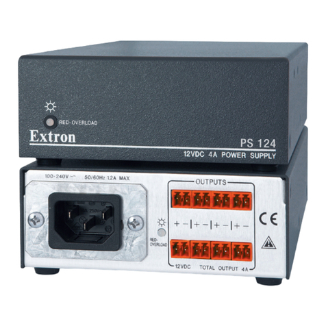
Extron electronics
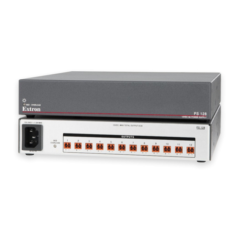
Extron electronics PS 124 User manual
Extron electronics
Extron electronics PS 128 User manual
Extron electronics
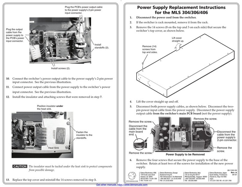
Extron electronics MLS 306 Guide

Extron electronics
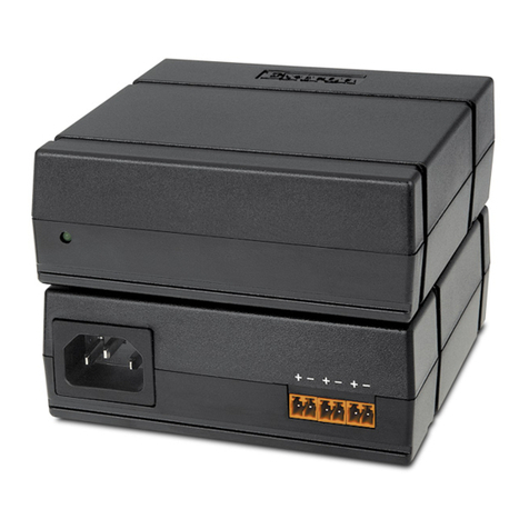
Extron electronics PS 125 User manual
Extron electronics
Extron electronics PS 1230 User manual

Extron electronics
Extron electronics PS 128 User manual
Extron electronics
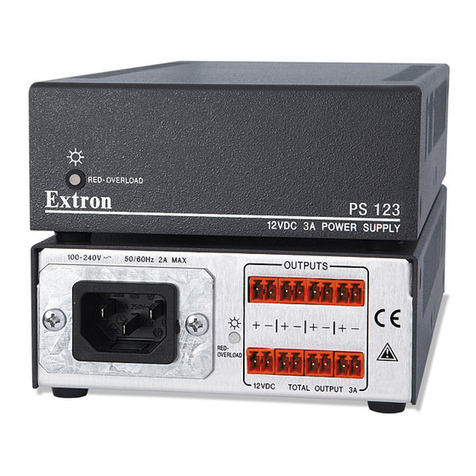
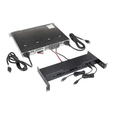
Extron electronics PS 123 User manual
Extron electronics
Extron electronics VNM 12 PS User manual
Extron electronics
Extron electronics PS 1220 User manual
Extron electronics
Extron electronics PS 1205 C User manual
Extron electronics
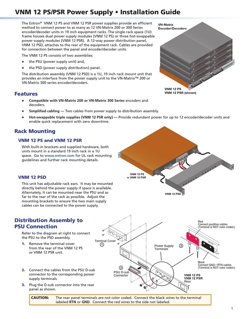
Extron electronics VNM 12 PS User manual
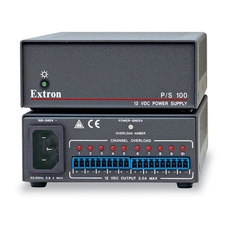
Extron electronics
Extron electronics P/S 100 User manual
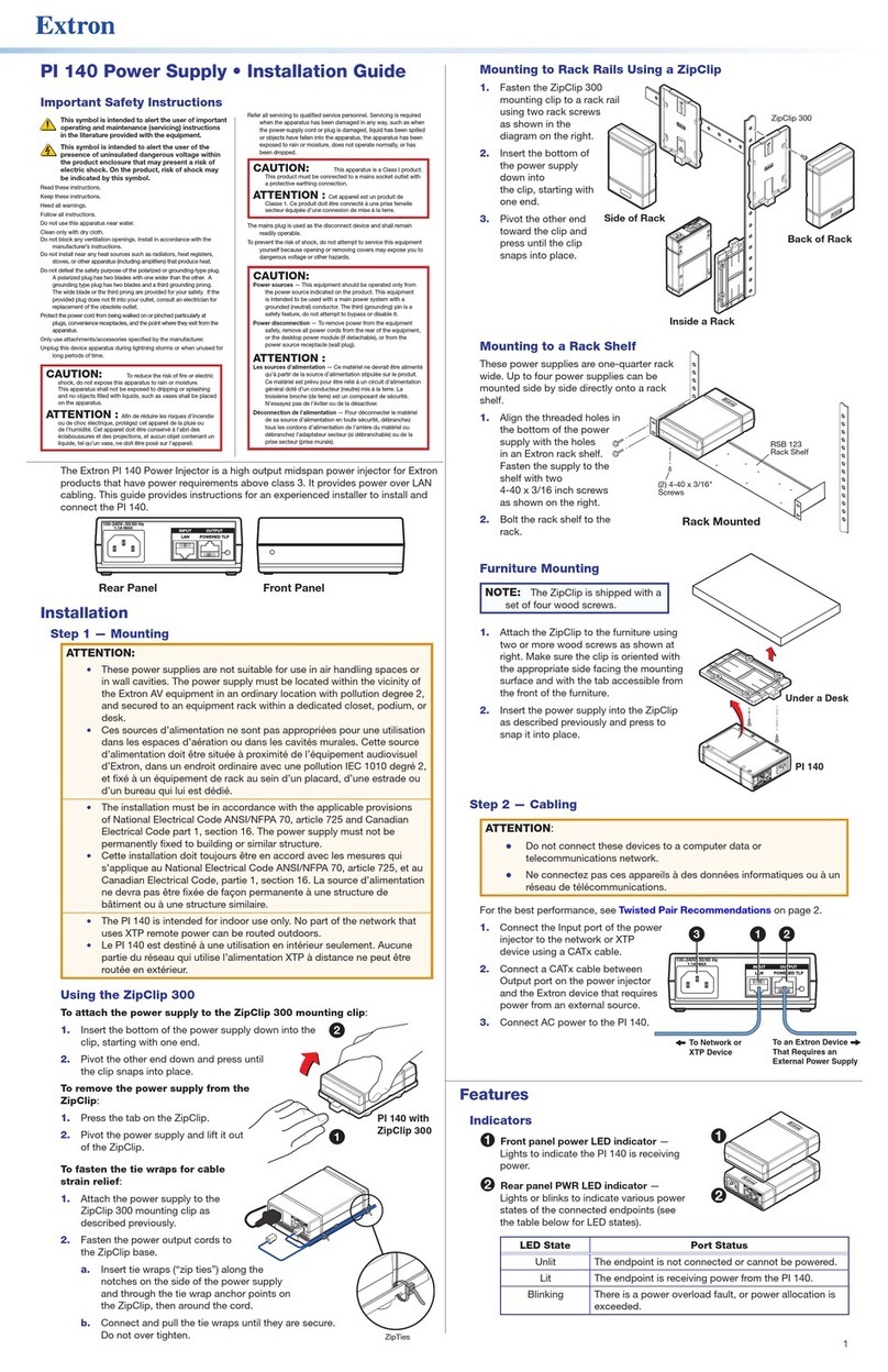
Extron electronics
Extron electronics PI 140 User manual
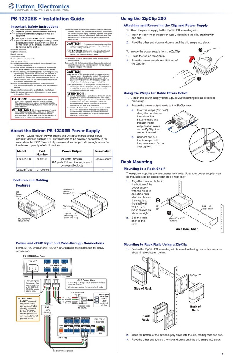
Extron electronics
Extron electronics PS 1220EB User manual
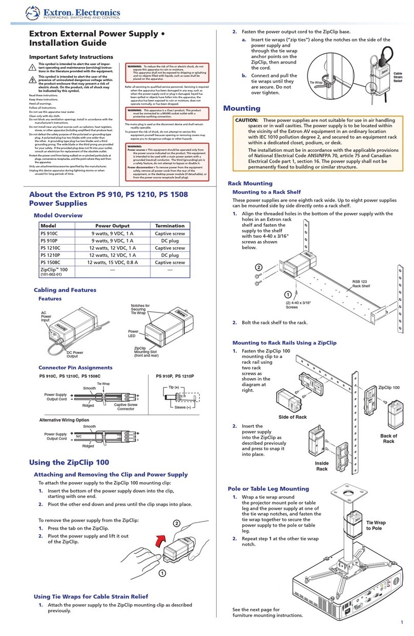
Extron electronics
Extron electronics PS 910C User manual
Extron electronics
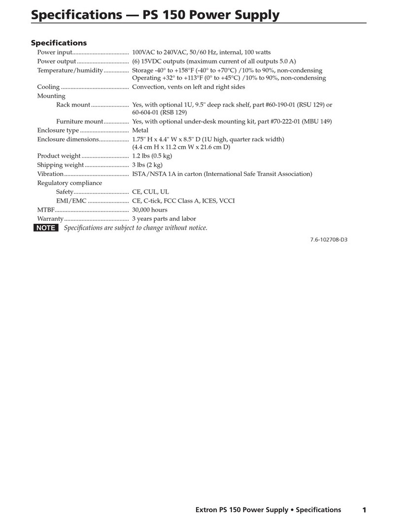
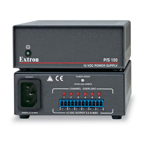
Extron electronics P/S 150 User manual
Extron electronics
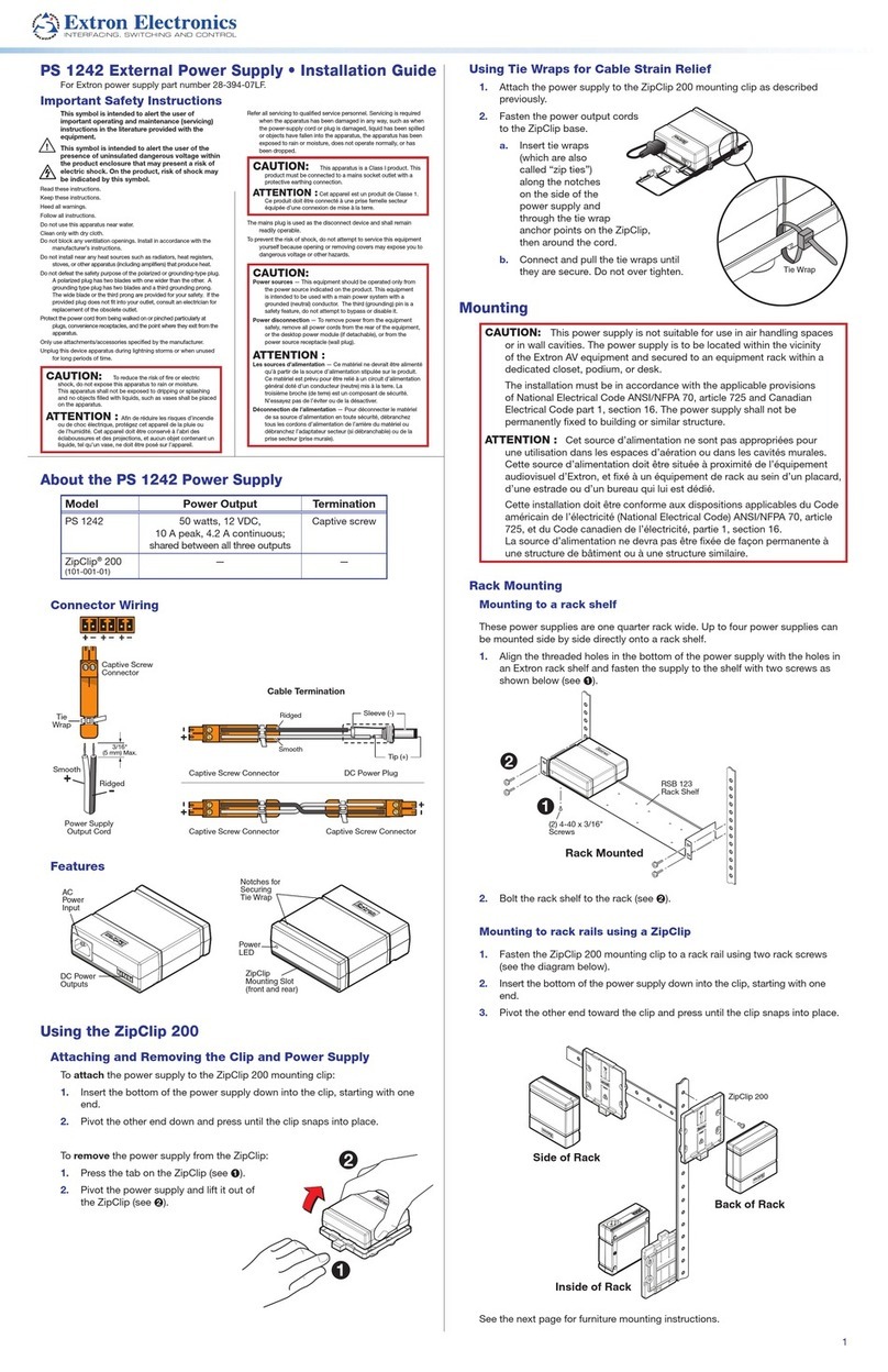
Extron electronics PS 1242 User manual
Extron electronics
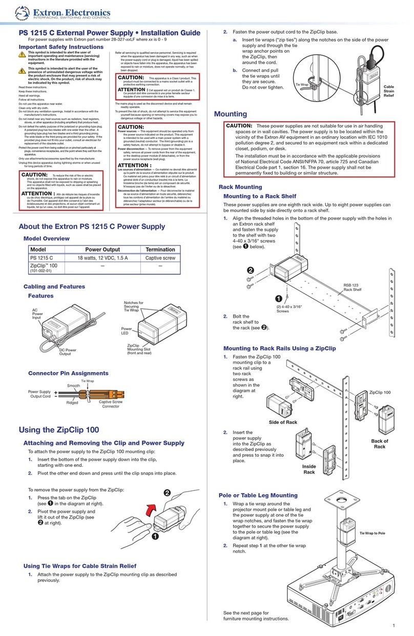
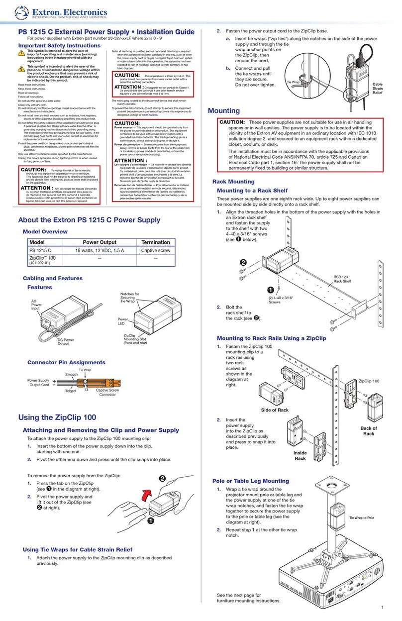
Extron electronics PS 1215 C User manual
Extron electronics
Extron electronics PS 1210 User manual
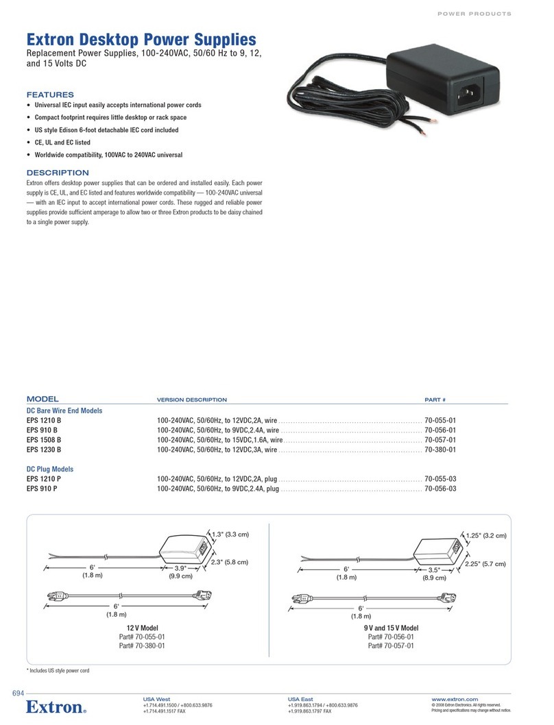
Extron electronics
Extron electronics EPS 1210 P User manual
Popular Power Supply manuals by other brands

Fencee
Fencee GW100 Instructions for use

WAGO
WAGO 2787-2147/0000-00 0 Series manual
Alpha Technologies
Alpha Technologies Alpha Outback Energy AlphaCap-665 Installation & operation manual
Bluetti
Bluetti AC180 user manual

Wybron
Wybron InfoTrace DPS850 user manual

Celestron
Celestron Powertank Lithium PRO instruction manual


