Fencee GW100 User manual

1
EN Electric fencing
Compatible
•fencee energy DUO RF EDX
•fencee power DUO RF PDX
•fencee Monitor MX10
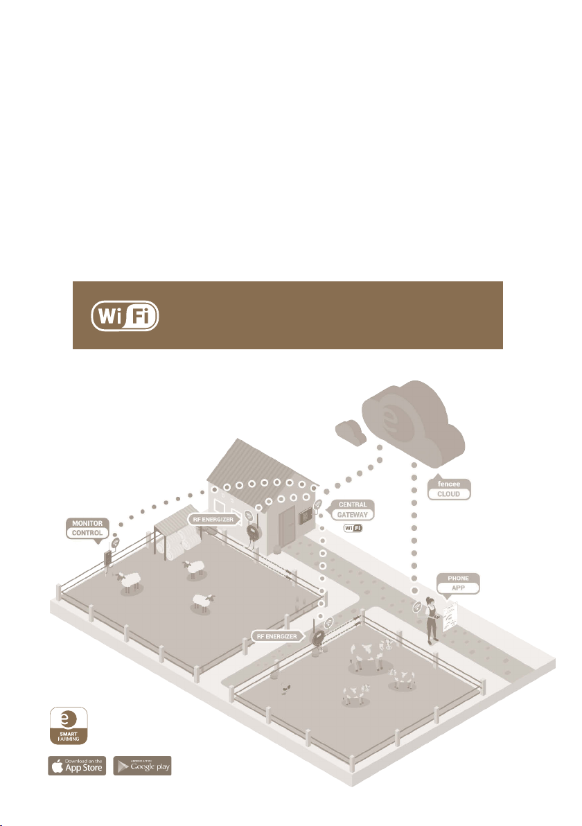
UPTODATE
INFORMATION
Online up-to-date
information on all devices.
Control and monitor
through mobile application.
PHONE
CONTROL
ALARM
SIGNALLING
Immediate problem alert sent
to the phone and e-mail.
INSTRUCTIONS
FOR USE
DEVICE FOR
REMOTE CENTRAL CONTROL
AND MANAGEMENT OF ELECTRIC FENCE

2
Thank you for purchasing this product
FENCE WiFi GATEWAY GW100 of the company VNT electronics s.r.o.
This device complies with the security regulations by the valid law same as for the appropriate EU (CE) regulation
The device complies with the EU directive 2014/53/EC,
Meets all requirements of General licence of the Czech telecommunications oce by the general authorization
n. VO-R/10/05.2014-3, as well it complies with the requirements of norms which are listed below and to the
relevant regulations for that kind of device:
ETSI EN 301 489-1 V1.9.2 I ETSI EN 301 489-3 V1.6.1 I ETSI EN 300 220-2 V.2.4.1
ETSI EN 60950-1 ed.2:2006 /A1:2010 /A11:2009 /A12:2011 /A2:2014/Opr.1:2012 EN 62479:2010
R&TTE EN300-220 a EN 61000-6-3:2007 + A1:2011
CSN EN 60335-1 I CSN EN 55014-1 I CSN EN 55014-2
1. CONTENT
1Content . . . . . . . . . . . . . . . . . . . . . . . . . . . . . . . . . . . . . . . . . . . . . . . . . . . . . . . . . . . . . . . . . . . . . . . . . . . . . . . . . . . 2
2Important recommendations . . . . . . . . . . . . . . . . . . . . . . . . . . . . . . . . . . . . . . . . . . . . . . . . . . . . . . . . . . . . . . . . . . . . . . . . . . . . . . . . . . . 3
3Package content . . . . . . . . . . . . . . . . . . . . . . . . . . . . . . . . . . . . . . . . . . . . . . . . . . . . . . . . . . . . . . . . . . . . . . . . . . . . . . . . . . . 3
4Introduction . . . . . . . . . . . . . . . . . . . . . . . . . . . . . . . . . . . . . . . . . . . . . . . . . . . . . . . . . . . . . . . . . . . . . . . . . . . . . . . . . . . . . . . . . . . . . . . 4
5List of main advantages . . . . . . . . . . . . . . . . . . . . . . . . . . . . . . . . . . . . . . . . . . . . . . . . . . . . . . . . . . . . . . . . . . . . . 5
6Gateway installation and fence connection . . . . . . . . . . . . . . . . . . . . . . . . . . . . . . . . . . . . . . . . . . . . . . . . . . . . . . 6
7Description of the device . . . . . . . . . . . . . . . . . . . . . . . . . . . . . . . . . . . . . . . . . . . . . . . . . . . . . . . . . . . . . . . . . . . . . . . . . . . . . . . . . 8
7.1 - Front side and operating touch keys . . . . . . . . . . . . . . . . . . . . . . . . . . . . . . . . . . . . . . . . . . . . . . . . . 8
7.2 - Back side . . . . . . . . . . . . . . . . . . . . . . . . . . . . . . . . . . . . . . . . . . . . . . . . . . . . . . . . . . . . . . . . . . . . . . . . . . . . . . . . 10
8Ready to use . . . . . . . . . . . . . . . . . . . . . . . . . . . . . . . . . . . . . . . . . . . . . . . . . . . . . . . . . . . . . . . . . . . . . . . . . . . . . 11
9Device manager - pairing device . . . . . . . . . . . . . . . . . . . . . . . . . . . . . . . . . . . . . . . . . . . . . . . . . . . . . . 12
9.1 - Pairing new device - energizer . . . . . . . . . . . . . . . . . . . . . . . . . . . . . . . . . . . . . . . . . . . . . . . . . . . . . . . . . . . . . . . . 12
9.2 - Pairing new device - monitor . . . . . . . . . . . . . . . . . . . . . . . . . . . . . . . . . . . . . . . . . . . . . . . . . . . . . . . . . . . . . . . . . . 14
9.3 - Subordinate monitor to the energizer . . . . . . . . . . . . . . . . . . . . . . . . . . . . . . . . . . . . . . . . . . . . . . . . . . . . . 16
9.4 - Editing device labels . . . . . . . . . . . . . . . . . . . . . . . . . . . . . . . . . . . . . . . . . . . . . . . . . . . . . . . . . . . . . . . 17
9.5 - Remove device . . . . . . . . . . . . . . . . . . . . . . . . . . . . . . . . . . . . . . . . . . . . . . . . . . . . . . . . . . . . . . . . . . . 17
10 Overview screen . . . . . . . . . . . . . . . . . . . . . . . . . . . . . . . . . . . . . . . . . . . . . . . . . . . . . . . . . . . . . . . . . . . . . . . . . 18
11 Detailed screen - energizer and monitor . . . . . . . . . . . . . . . . . . . . . . . . . . . . . . . . . . . . . . . . . . . . . . . . . . . . . . . . . . . . . 20
12 Menu - setting of the device . . . . . . . . . . . . . . . . . . . . . . . . . . . . . . . . . . . . . . . . . . . . . . . . . . . . . . . . . . . . . . . . . . . . . . . . . . . . . . 21
12.1 - Sound settings . . . . . . . . . . . . . . . . . . . . . . . . . . . . . . . . . . . . . . . . . . . . . . . . . . . . . . . . . . . . . . . . . . . . . . . . . . 21
12.2 - Display settings . . . . . . . . . . . . . . . . . . . . . . . . . . . . . . . . . . . . . . . . . . . . . . . . . . . . . . . . . . . . . . . . . . . . . . . . . . 22
12.3 - Advance settings . . . . . . . . . . . . . . . . . . . . . . . . . . . . . . . . . . . . . . . . . . . . . . . . . . . . . . . . . . . . . . . . . . . 22
12.4 - Device information . . . . . . . . . . . . . . . . . . . . . . . . . . . . . . . . . . . . . . . . . . . . . . . . . . . . . . . . . . . . . . . . . . . . . . 26
13 Wi-Fi connection . . . . . . . . . . . . . . . . . . . . . . . . . . . . . . . . . . . . . . . . . . . . . . . . . . . . . . . . . . . . . . . . . . . . . . . . . . . . . . 26
14 fencee Cloud application . . . . . . . . . . . . . . . . . . . . . . . . . . . . . . . . . . . . . . . . . . . . . . . . . . . . . . . . . . . . . . . . . . . . . . . . . . . . . . 30
15 Error reporting, signaling, deleting . . . . . . . . . . . . . . . . . . . . . . . . . . . . . . . . . . . . . . . . . . . . . . . . . . . . . . . . . . . . 31
16 Reset to factory settings . . . . . . . . . . . . . . . . . . . . . . . . . . . . . . . . . . . . . . . . . . . . . . . . . . . . . . . . . . . . . . . . . . . 32
17 Possible sources of problems . . . . . . . . . . . . . . . . . . . . . . . . . . . . . . . . . . . . . . . . . . . . . . . . . . . . . . . . . . . . . . . . . . . . . . . . . 32
18 Hole drilling template . . . . . . . . . . . . . . . . . . . . . . . . . . . . . . . . . . . . . . . . . . . . . . . . . . . . . . . . . . . . . . . . . . . . . . . . . 33
19 Guarantee . . . . . . . . . . . . . . . . . . . . . . . . . . . . . . . . . . . . . . . . . . . . . . . . . . . . . . . . . . . . . . . . . . . . . . . . . . . . . . . . . . . . 35
20 Technical parameters . . . . . . . . . . . . . . . . . . . . . . . . . . . . . . . . . . . . . . . . . . . . . . . . . . . . . . . . . . . . . . . . . . . . . . . . . 35

3
We recommend that this manual is read thoroughly and fully understood
before using the device and that it is retained for future reference!
Only use the original 14 V/1 A adapter to supply the gateway. The supply voltage must not
exceed 16 V.
· The gateway is not waterproof; ingress of water may irreparably damage it.
· Strictly observe all safety guidelines during installation work.
· The device may only be repaired by the manufacturer’s qualied personnel.
· Please dispose all waste in accordance with your country’s code of practice.
· The displayed output voltage tolerance is ±10%.
2. IMPORTANT RECOMMENDATIONS
3. PACKAGE CONTENTS
• FENCE WiFi GATEWAY GW100
• RF antenna
• 14 V/1 A power supply adapter for mains connection
• 9.6 V backup battery power supply
• 2 installation self-tapping screws and rawlplugs
• User Manual
To connect the gateway to Wi-Fi network, MAC address and
PIN are required, which are given on the label attached to the
back of this User Manual and in the product box. Keep this
information safe as it may be used in the event of changes to
the gateway conguration
4
4. INTRODUCTION
FENCEWiFi GATEWAY GW100 enables remote central monitoring and control of the energizers
and monitors. Up to twelve independent energiuers or connected control devices, monitors
MX10, may be controlled within the antenna range. The gateway gathers all information
relating to the operation of all connected devices.
· All important information relating to the fence system is presented to the user in well-
arranged format; the user has the option to set limit for triggering alarm for each fence and
monitor, which will generate alert if the set limits are exceeded.
· Energizers may be remotely switched o, switched on, power output changed (50%/100%)
and alarms set.
· It receives data relating to the fence system voltage from the monitor. The alarm limit may
be set on the gateway and when it falls below the set limit, the alarm indicates status change.
Using Wi-Fi connection, the user has the ability to monitor and
control all connected devices from mobile phone using the
application or via web browser.
Free app
fencee Cloud

5
5. LIST OF MAIN ADVANTAGES
Online monitoring and control of connected devices from mobile phone using the
application or via web browser
· Monitoring and control of up to 12 energizers and monitors
· Well-arranged, intuitive touch control
· Radio connection (RF) with energizers and monitors
· SIM card is not required
· All essential information together in one device
· Large, fully graphic LCD display
· Overview screen with information relating to all energizers and monitors
· Detailed display of parameters of each energizer and monitor
· Settable alarm limit for each connected device
· Mains supply + backup battery power supply
· Option to connect external warning system (siren, light)
WELLARRANGED
GRAPHS
LIST OF
DEVICES
ONLINE
ALARMS
MAP
BASE
NO SIM CARD
NEEDED
TIME
SAVING
Keep track with mobile application fencee Cloud
More on page 30

6
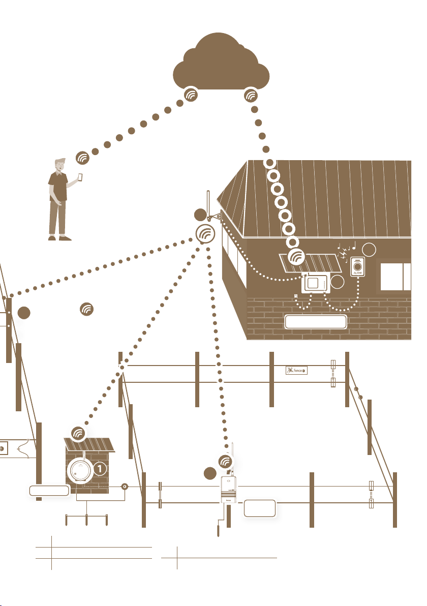
9High voltage connection cable
10 Conductor
11 Line connector
12 Fixed post
1Energizer
2Gateway WiFi GW100
3Monitor MX10
4External RF antenna
5External alarm with siren
6Earthing cable
7Anticorrosive earthing rod
8Lightning diverter
6
10
16
7
8
9
11
12
13
15
17
9
6. GATEWAY INSTALLATION AND FENCE CONNECTION
Before installing the gateway, please read all the security instructions in this manual
carefully. For wall mounting, use the enclosed screws to easily hang the gateway.
Choose the right place where gateway is:
• The gateway is securely protected against water and moisture.
INCREASE OF WATER COULD CAUSE IRREVERSIBLE DAMAGE
• Not exposed to direct sunlight.
• An electrical outlet (230V) is nearby.
RF energizer G1
7
13 Tensioner
14 IInsulators
15 Warning sign
Gateway GW100
3
4
5
14
2
CLOUD
16 Gate
17 Insulator of gate
Monitor
MX10
RF energizer G2
8
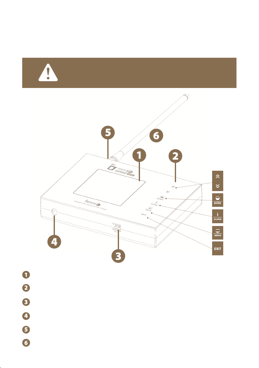
Graphic display with backlight
Touch control panel
Connector with relay, for external signaling
Power adapter connector
SMA connector for antenna connection
Radio RF antenna
THE DEVICE CAN DISTINGUISH TWO TYPES OF PRESS:
· Short press
· Long press (more than 1 s)
7. DESCRIPTION OF THE DEVICE
7.1 Front side and operating touch keys
The device can be operated using the touchpad shown.

9
Screen Functions
All Device selection in detailed and overview screen.
Changing values in setup mode, navigating through menus.
Overview
and detailed
screen
Short press - turns ON / turns OFF
Long press - switching power (50 / 100 %)
Menu
and setting
Short press - confirm, enter to another screen.
Long press - deleting of device from gateway.
Overview
and detail
screen
Short press - asking the selected device for up-to-date
information. In case of error signaling, confirmation
and deleting alerts.
Long press - setting the pulse voltage limit
If it falls below the set limit, the alarm is triggered.
Overview
and detail
screen
Short press - switch between detail and overview screen
Long press - enter the menu
Overview
and detailed
screen
Long press - switch off gateway.
Menu Short press - return to previous screen.
Switched
off screen Long press - switch on gateway.
KEYBOARD FUNCTION:
It does not work on the monitor
10
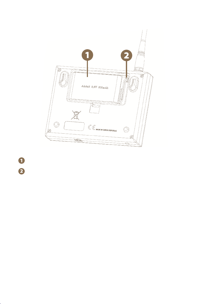
7.2 Back side
Backup battery
Socket for connecting the backup battery connector.

11
WARNING:
Operating the device without mains power and only with very
low battery charge may result in incorrect device operation!
Before commencing, connect the gateway to the mains,
otherwise ECO Mode will start automatically (refer to Page 23)
and the gateway will not be fully functional.
Main screen without connected devices
8. READY TO USE
Inserting backup battery
9.6 V backup battery power supply used in the event of mains power failure is able to supply
the device for up to one day, however it depends on the device settings such as backlight or
volume.
· Open the device back cover.
· Plug the backup battery connector into the socket.
· Insert the backup battery into the designated location and return the cover to its original
position.
Connect the gateway to the mains using the power supply adapter.
Connect RF antenna to SMA connector.
Press and hold the touch key to turn the gateway on.
12
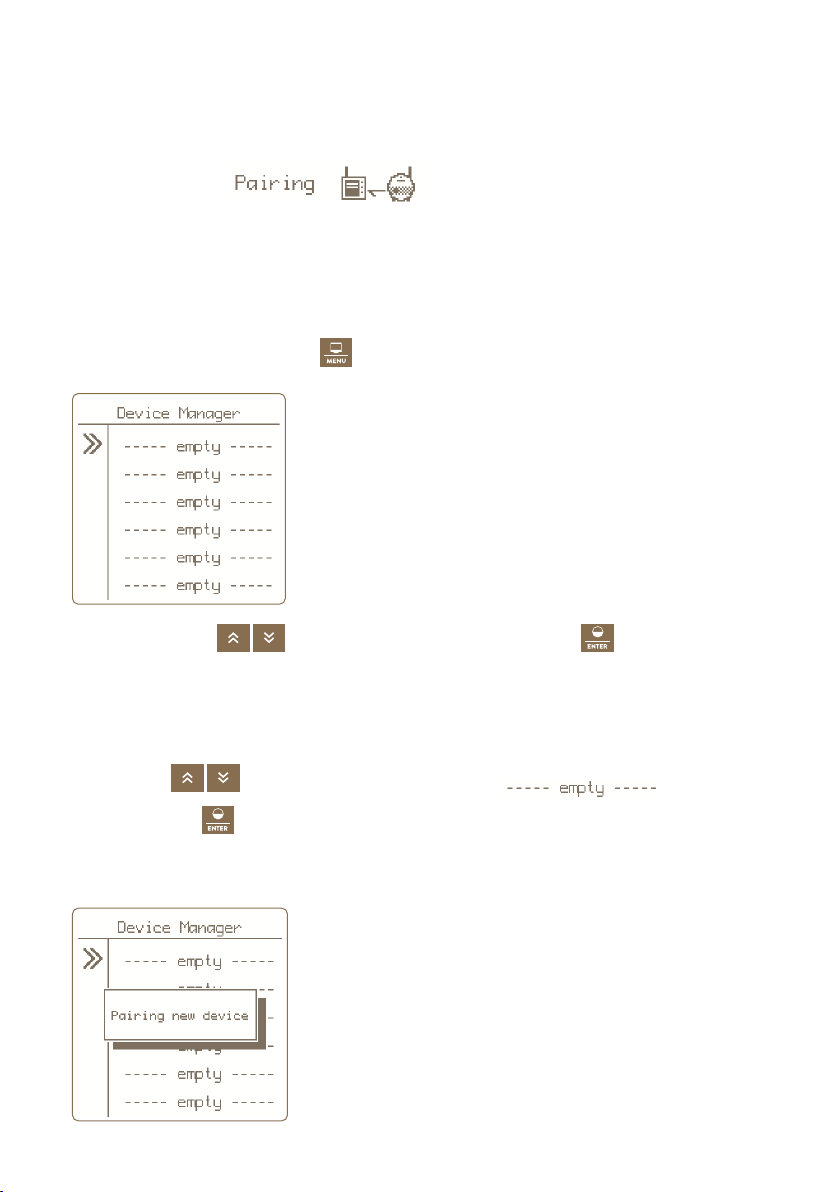
9. DEVICE MANAGER PAIRING DEVICE
Device Manager is used for pairing, editing and deleting devices (energizers and monitors) in
the gateway.
Pairing Device -
Pairing is the process of linking communication between two devices. The gateway
GW100 can pair up to twelve different devices. The device can be renamed individually.
If all positions are occupied, it is not possible to start a new pairing!
9.1 Pairing new device - energizer
To select pairing, press and hold .
1. Use the arrows to move to Pairing and by press the
key you will get to
the Device Manager where you work with the device.
2. Switch the energizer to pairing mode - Switch on energizer and then switch it off with
one short press. Then press and hold the button (> 5 seconds), until the LED flashes
very quickly. Now is energizer in pairing mode. Place the device close to Gateway.
3. By arrows move the cursor to an empty item
4. Short press of
key we confirm the chosen item.
5. The correct selection of the action is confirmed by the Pairing new device information
screen.
13
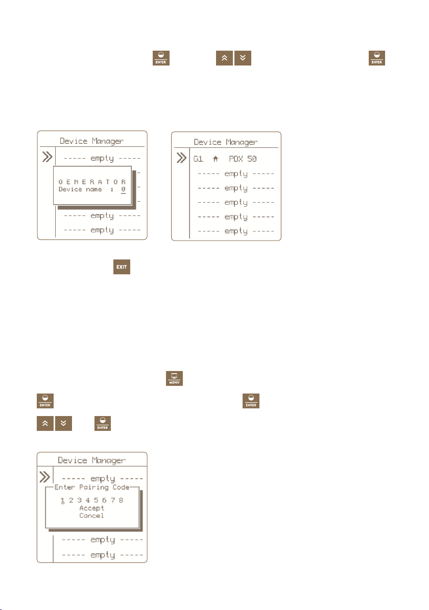
6. If pairing is successful, a menu is displayed for editing the displayed device.
7. Editing - for entering press
by arrows, choose marking and confirm
.
8. Press the button to return to the main settings .
Optional designation: 1 -12
Only labels that have not yet been used are offered.
Remote Pairing
The gateway GW100 also enables remote pairing for energizers energy DUO RF EDX. This me-
ans that you do not have to have a energizer directly at the gateway to be able to pair it. Pai-
ring can be performed over long distances using a code. Code activation in the EDX energizer
is described in the EDX manual.
This choice you call by holding , you move on Pairing and confirm by press the key
. You will choose free position and by long press
you activate it. You input Code by
and
.

14
9.2 Pairing new device - monitor
To select pairing, press and hold .
1. Use the arrows to move to Pairing and by press the
key you will get to
the Device Manager where you work with the device.
2. Switch the monitor to pairing mode:
• Switch off the monitor with a magnet, the LED flashes red.
• Then reattach the magnet to the target on monitor and hold until both LEDs
(green and red) flashes on the monitor.
• The monitor is now in pairing mode.
• Place the device close to the gateway.
3. By arrows move the cursor to an empty item
4. Short press of
key you confirm the chosen item.
5. The correct selection of the action is confirmed by the Pairing new device information
screen.
6. If pairing is successful, a menu is displayed for editing the displayed device.

15
Optional designation:
• Device name: A - L only a designation that is not yet used is offered.
• Associated to: see explanation on page 16 monitor Subordination.
7. Editing - for entering press
, by arrows choose marking and confirm
.
8. Press the button to return to the main settings .
16
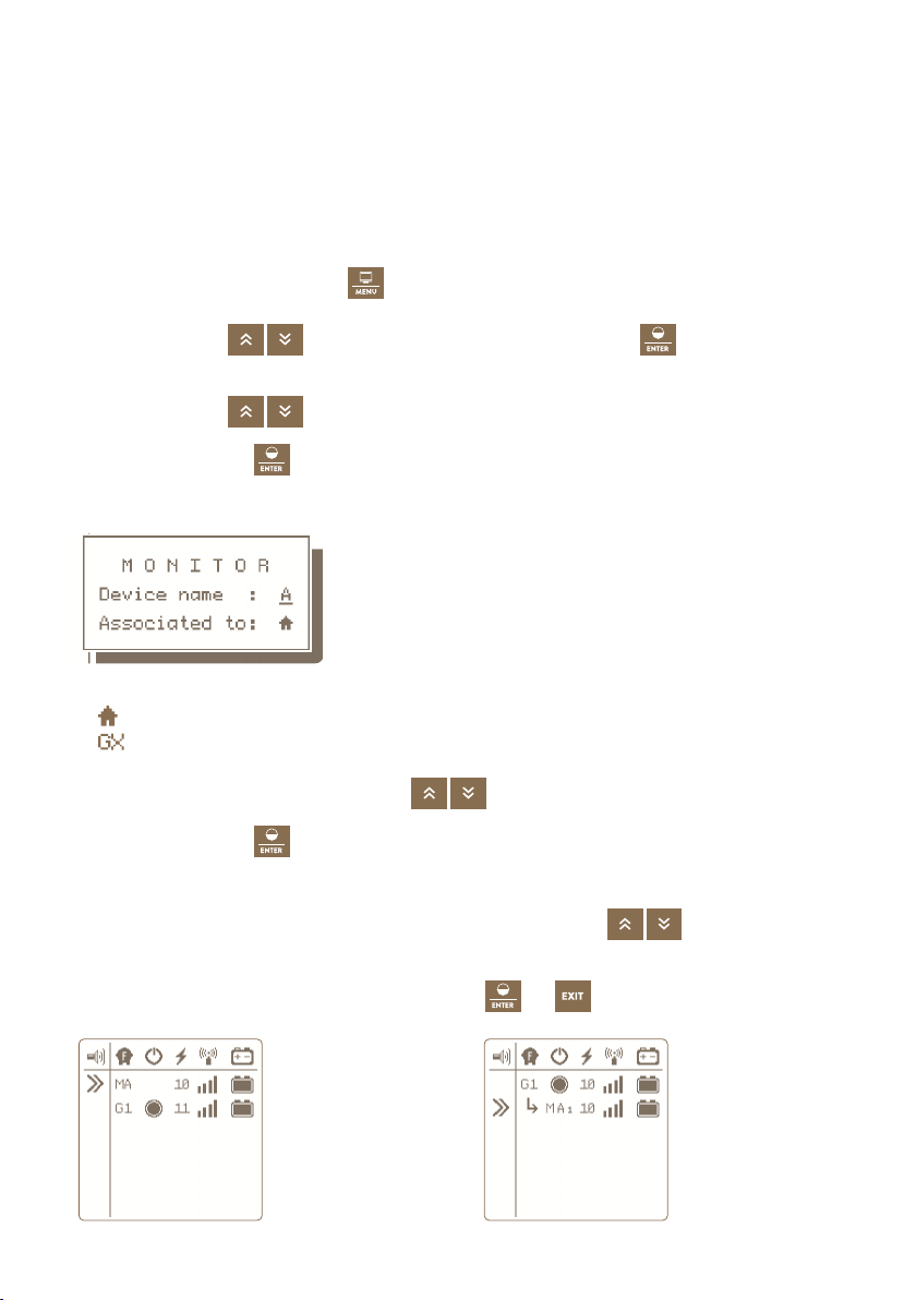
9.3. Subordinate monitor to the energizer
If you place one or more monitors on a fence powered by a specific energizer,
we recommend that these monitors be subordinated to the energizer.
The main advantage is that if the energizer is intentionally switched off, no alarm is indicated
on the monitors. And there is a better visual differences on the gateway display.
Procedure for setting subordination - in Device Manager:
To select pairing, press and hold .
1. Use the arrows to move to Pairing and by press the key
you will get to the
Device manager where you work with the device.
2. Use the arrows to move to desired item.
3. By short press key
you confirm choice of the monitor.
4. After confirmation, a pop-up window will appear showing the current settings.
5. Subordination is indicated on the line Associated to:
house - monitor is independent, is not subordinate
- monitor is subordinate to this energizer
6. If you want to change, use the arrows to move to Associated to.
7. By short press key
you confirm your choice.
8. Editing is now signaled by flashing of the entered value, which can be changed
to the desired name of the superior energizer with the arrows .
Note: values that cannot be selected are automatically skipped.
9. To confirm the change, shortly press the Enter
or button.
Overview
screen with the
independent
monitor
Overview
screen with the
subordinated
monitor - to
energizer G1
17
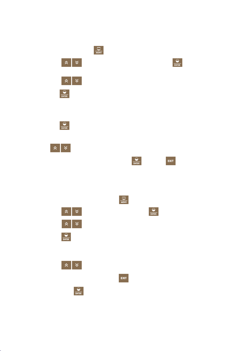
9.4 Editing device labels
Paired devices can be assigned a distinguishing sign.
Each device can only be assigned a name that is not yet in use.
To select editing, press and hold .
1. Use the arrows to move to Pairing and by press the key
you will get to
the Device manager where you work with the device.
2. Use the arrows to move to desired item.
3. By short press
key you confirm choice of the item.
4. After confirmation, an information window appears showing the current settings.
5. The setting of the displayed marking is displayed by the Device name item.
6. By short press
key you confirm our choice.
7. Editing is now signaled by blinking of the entered value, which can be set
by arrows . Note: the values that you cannot choose are skipped automatically.
8. The change can be confirmed by short press of
key or by key.
9.5 Remove device
To remove a device from the list of paired devices, follow the procedure below.
To remove the selection, press and hold the key.
1. Use the arrows to move to Pairing and press
key to manage the device.
2. Use the arrows to move to desired item.
3. Long press the
key to enter the delete menu.
4. Correct selection of the action is confirmed by pop-up window with DELETE + the name
of the selected device.
5. Use the arrows to select the option Ye s to select delete, Cancel to deleting.
Note: You can also cancel by pressing the key.
6. By short press of the
key you confirm selected action.
18
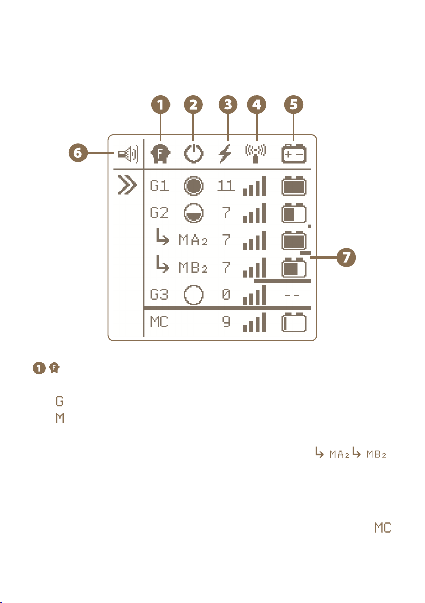
10. OVERVIEW SCREEN
The screen provides an immediate overview of all connected devices.
GX or MX marking
indicates a generator device (energizer)
indicates a monitor device
Xindicates optional name to distinguish between energizers 1 - 12 or monitors A - L
The monitor can be installed subordinate to the energizer - see
Subordination means that the monitor check the same fence where the voltage is being
generated by superior energizer. If the fence is intentionally switched off, no recall occurs
alarm on the monitor. In the case of subordinate monitor, the designation is
supplemented by a name of superior energizers (in this case G2, ie the designation
of monitor MA2, MB2).
Or the monitor can be installed separately, independent of the energizer - see
Energizers or monitors with identical names cannot be operated on the gateway.
Type of device
19
• energizer is completely switched off and does not communicate.
This status is not indicated for the monitor.
Energizer state and its power
• power 50% - the energizer is switched on and set to half power
see energizer G2
• power 100% - the energizer is turned on and set to full power
see energizer G1
Last measured voltage at the fence [kV]
Signal level of the connected energizer
Displays the battery status when is connected to energizer or displays
status of monitor´s battery
Indication of activation of the audible alarm - see page 21
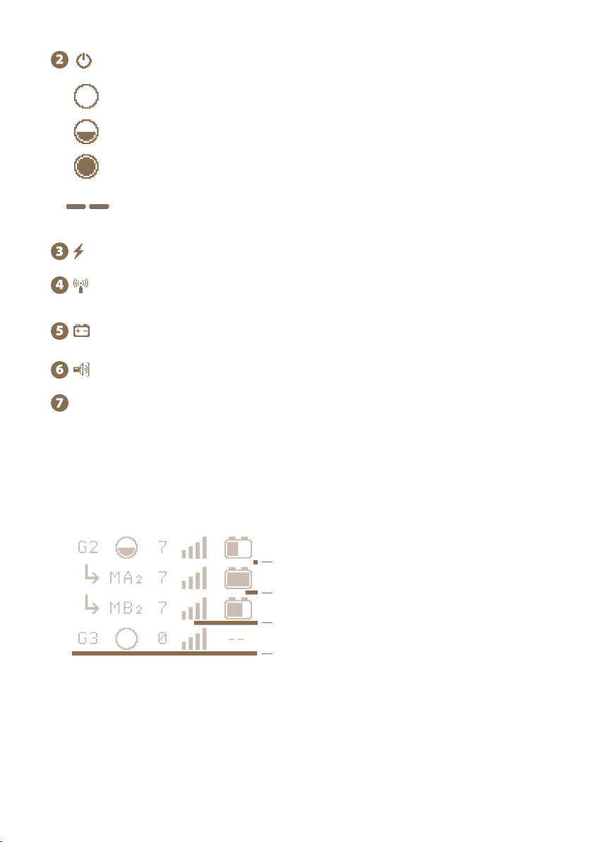
Indication of last device response
Under each device is a bargraph, which signals the time since the last sent information
about the status of the remote device. The transmission interval between the energiter
and the gateway is each minute, between the monitor and the gateway every 15 minutes.
The bargraph is displayed from 2 minutes since the last transmission. If the entire device
is underlined, an alarm is set automatically. If at any time during the transmission with
information about the device, the bargraph is zeroed and starts to be timed again.
• power 0% - energizer is off, the device communicates (in standby mode)
see energizer G3
20 minutes
60 minutes
2 minutes
5 minutes

20
The name of device (possibility to change by user)
There is displayed MAC address of the connected device under the name.
Energizer state and its power
This status is not indicated for the monitor.
Signal level between device and gateway
The value of the voltage on the fence [kV]
Current alarm value [kV]
The time since the last information received from the device
Battery voltage status when connected to energizer [V]
Or battery status of the monitor [%]
Energizer´s performance according to the current load (impedance) of the fence
system. Only for EDX series energizers.
MAC address fo device (energizer, monitor)
Current load (impedance) of the fence, displayed in Ohms (the lower the number,
the more loaded the fence) and a symbolic graphic expression.
Only for EDX series energizers.
Gateway to Wi-Fi connection status
online – the gateway is connected and communicates with Wi-Fi
conn. Wifi – gateway is not connected to Wi-Fi, for communication is necessary to confi-
gure WIFI connection
8
9
10
11
11. DETAILED SCREEN ENERGIZER AND MONITOR
Detailed screen is used to show all the possible information about concrete device.
Table of contents
Other Fencee Power Supply manuals


Popular Power Supply manuals by other brands


Westinghouse
Westinghouse 91308 quick start guide

Seasonic
Seasonic X-650W owner's manual

Manson Engineering Industrial
Manson Engineering Industrial HCS-3404 user manual

Agilent Technologies
Agilent Technologies 6023A operating manual

FEAS
FEAS SNT230 operating instructions

Pyle Pro
Pyle Pro PDBC60 owner's manual


