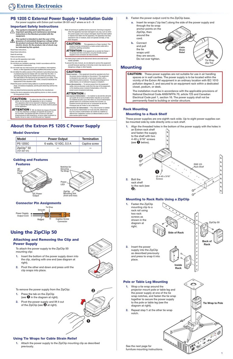
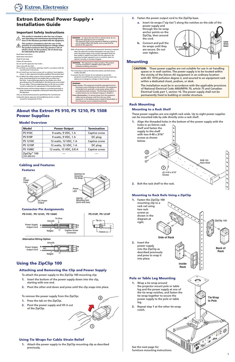
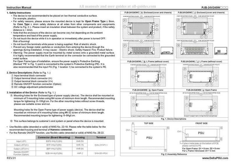
manuals.online logo
Brands
  1. Home
  2. •
  3. Brands
  4. •
  5. Extron electronics
  6. •
  7. Power Supply
  8. •
  9. Extron electronics PS 128 User manual

Extron electronics PS 128 User manual

IMPORTANT:
Go to www.extron.com for the complete
user guide,
installation instructions,
and
specifications bef
ore connecting the
pr
oduct to the po
wer source.
IMPORTANT:
Go to www.extron.com for the complete
user guide,
installation instructions,
and
specifications bef
ore connecting the
pr
oduct to the po
wer source.
PS 128 Power Supply • Setup Guide
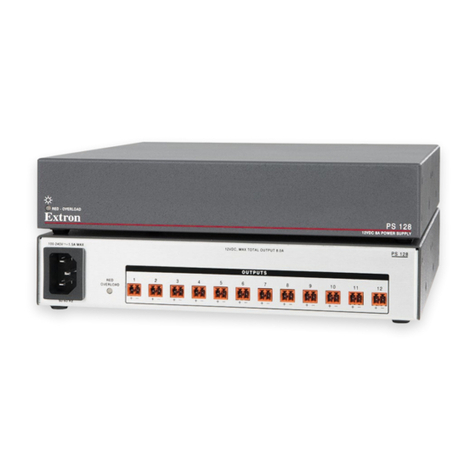
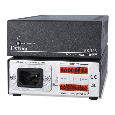
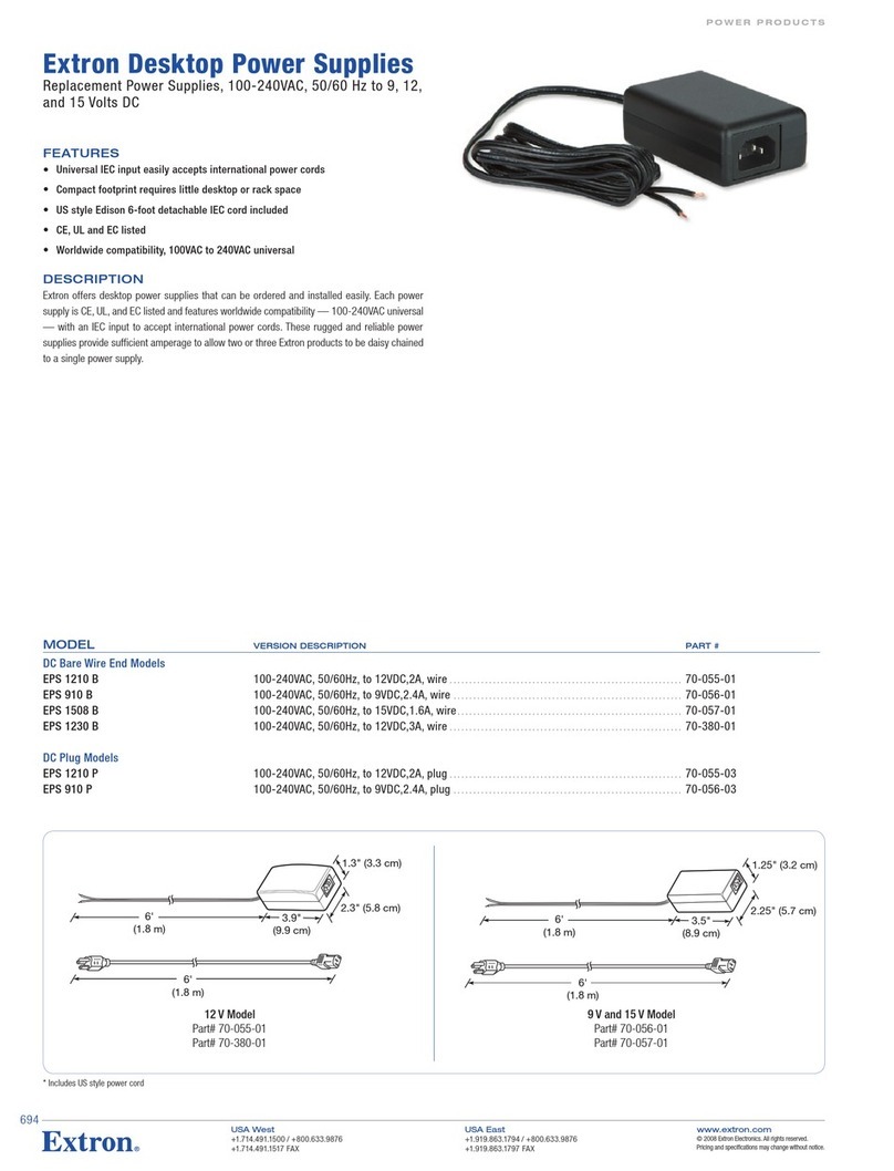
The PS 128 Power Supply is a half rack width power supply with 12 outputs. It supplies
12 VDC, 8 A DC power for up to 96 watts. It is compatible with any Extron product featuring
2-pole, 3.5 mm captive screw power connectors. This guide provides instructions for an
experienced installer to install and connect the PS 128 Power Supply.
Installation
Mount the Device
1. Turn off or disconnect all equipment power sources.
2. Mount the PS 128 in one of the following methods (see www.extron.com for optional
mounting kits and additional mounting instructions):
•Mount the PS 128 in a rack (with an optional 1U mounting kit).
•Mount the PS 128 to furniture (with an optional furniture mounting kit).
•Mount the PS 128 in an Extron Pole Vault system (with an optional mounting kit).
If using an optional mounting kit, see the mounting kit instructions for additional mounting
considerations and instructions.
Connect Devices and Power
The PS 128 can power up to 12 devices simultaneously. For each device to receive power,
connect power cables to the 2-pole, 3.5 mm captive screw connectors on the rear panel of the
PS 128. Then, apply power to the device.
OUTPUTS
RED -
OVERLOAD
PS 128
100-240VAC 50/60 Hz
1.5 A MAX
1
+-
2
+-
3
+-
4
+-
5
+-
6
+-
7
+-
8
+-
9
+-
10
+-
11
+-
12
+-
AB C
ADC output connectors (see the next page)
BAC power connector (see the next page)
COverload LED indicator (see figure 2, Aon the next page)
Figure 1. Output Connectors and LED Indicator
PS 128 Power Supply • Setup Guide (Continued) PS 128 Power Supply • Setup Guide (Continued)
68-2900-50
Rev. B01 22
68-2900-50
Rev. B 01 22
Extron Headquarters
+1.800.633.9876 (Inside USA/Canada Only)
Extron Asia
+65.6383.4400
Extron China
+86.21.3760.1568)
Extron Australia
+61.8.8351.2188
Extron Europe
+31.33.453.4040
Extron Japan
+81.3.3511.7655
Extron Middle East
+971.4.299.1800
Extron India
+91.80.3055.3777
© 2016 Extron Electronics All rights reserved. www.extron.com
A DC output connectors — Connect up to 12 devices to these 2-pole, 3.5 mm captive screw
connectors (see figure 1, Aon the previous page). Wire the connectors as shown in the
image to the right. The outputs provide up to 12 VDC and 8 amps of current collectively.
WARNING: Electric shock hazard. The two power
cord wires must be kept separate while the power
supply is plugged in. Remove power before wiring.
AVERTISSEMENT : Risque de choc électrique
grave. Les deux cordons d’alimentation doivent être
tenus à l’écart l’un de l’autre quand l’alimentation
est branchée. Couper l’alimentation avant de faire
l’installation électrique.
NOTE: To verify proper polarity before connection to
a device, plug in the power supply with no load and
check the output polarity with a voltmeter. Remove
power before continuing.
BAC input connector — Connect a 100-240 VAC, 50-60 Hz power source to the AC power
connector (see figure 1, B) on the rear panel.
Operation
RED - OVERLOAD
PS 128
12VDC 8A POWER SUPPLY
A
Figure 2. Power and Overload LED indicator
AOverload LED indicator — Lights green when power is applied and current draw is normal
(under 8 amps) or red when the PS 128 is in a current overload condition (over 8 amps or
96 watts). There is also a duplicate Overload LED indicator on the rear panel
(see figure 1, Con the previous page).
ATTENTION:
•Continued operation in an overload condition may cause premature power supply
failure.
•Un fonctionnement ininterrompu dans un état de surcharge est susceptible de
provoquer une défaillance prématurée de l’alimentation électrique.
NOTE: To identify a shorted output, unplug the outputs one at a time until the LEDs
light green.
SECTION A–A
AA
Power Supply
Output Cord
2-Pole Captive Screw
Connector
Ridges
Smooth
Tie Wrap
3/16”
(5 mm) Max.
Other manuals for PS 128

1

Other Extron electronics Power Supply manuals

Extron electronics PS 910C User manual

Extron electronics

Extron electronics PS 910C User manual

Extron electronics VNM 12 PS User manual

Extron electronics

Extron electronics VNM 12 PS User manual

Extron electronics PS 1220EB User manual

Extron electronics

Extron electronics PS 1220EB User manual

Extron electronics P/S 100 User manual

Extron electronics

Extron electronics P/S 100 User manual

Extron electronics Quantum Ultra User manual

Extron electronics

Extron electronics Quantum Ultra User manual

Extron electronics PS 1215 C User manual

Extron electronics

Extron electronics PS 1215 C User manual

Extron electronics PS 1210 User manual

Extron electronics

Extron electronics PS 1210 User manual

Extron electronics MLS 306 Guide

Extron electronics

Extron electronics MLS 306 Guide

Extron electronics EPS 1210 P User manual

Extron electronics

Extron electronics EPS 1210 P User manual

Extron electronics PS 150 User manual

Extron electronics

Extron electronics PS 150 User manual

Extron electronics PS 1242 User manual

Extron electronics

Extron electronics PS 1242 User manual

Extron electronics PS 128 User manual

Extron electronics

Extron electronics PS 128 User manual

Extron electronics PS 1220 User manual

Extron electronics

Extron electronics PS 1220 User manual

Extron electronics VNM 12 PS User manual

Extron electronics

Extron electronics VNM 12 PS User manual

Extron electronics PS 1205 C User manual

Extron electronics

Extron electronics PS 1205 C User manual

Extron electronics PS 124 User manual

Extron electronics

Extron electronics PS 124 User manual

Extron electronics PS Series User manual

Extron electronics

Extron electronics PS Series User manual

Extron electronics Quantum Ultra User manual

Extron electronics

Extron electronics Quantum Ultra User manual

Extron electronics PS 1215 C User manual

Extron electronics

Extron electronics PS 1215 C User manual

Extron electronics P/S 150 User manual

Extron electronics

Extron electronics P/S 150 User manual

Extron electronics PS 124 User manual

Extron electronics

Extron electronics PS 124 User manual

Extron electronics PI 140 User manual

Extron electronics

Extron electronics PI 140 User manual

Extron electronics PS 1230 User manual

Extron electronics

Extron electronics PS 1230 User manual

Extron electronics PS 123 User manual

Extron electronics

Extron electronics PS 123 User manual

Popular Power Supply manuals by other brands

H3C PSR2400-D manual

H3C

H3C PSR2400-D manual

MRC PWR-3030 Operation manual

MRC

MRC PWR-3030 Operation manual

Monster Power Reference PowerCenter HTS2600 owner's manual

Monster Power

Monster Power Reference PowerCenter HTS2600 owner's manual

GMI D5015SS instruction manual

GMI

GMI D5015SS instruction manual

Eaton Power Xpert 9395 UPS Installation and operation manual

Eaton

Eaton Power Xpert 9395 UPS Installation and operation manual

Sense KFT-2410R instruction manual

Sense

Sense KFT-2410R instruction manual

Pyramid GOLD SERIES PS-12K instruction manual

Pyramid

Pyramid GOLD SERIES PS-12K instruction manual

Mustek POWERMUST 636 Specifications

Mustek

Mustek POWERMUST 636 Specifications

Televes UPSU120 user manual

Televes

Televes UPSU120 user manual

Analytic Systems PWS1505 Installation & operation manual

Analytic Systems

Analytic Systems PWS1505 Installation & operation manual

StarTech.com ATX2POW450HS instruction manual

StarTech.com

StarTech.com ATX2POW450HS instruction manual

Altronix Vertiline8C installation guide

Altronix

Altronix Vertiline8C installation guide

Furrion Trekker 500 Installation and owner's manual

Furrion

Furrion Trekker 500 Installation and owner's manual

BEL TEC2200-12-074NA installation instructions

BEL

BEL TEC2200-12-074NA installation instructions

Elektro-Automatik PS 9080-50 operating guide

Elektro-Automatik

Elektro-Automatik PS 9080-50 operating guide

Solar Stik 24VDC PRO-VERTER 5000-220 AGS Programming instructions

Solar Stik

Solar Stik 24VDC PRO-VERTER 5000-220 AGS Programming instructions

Altronix SMP10 quick start guide

Altronix

Altronix SMP10 quick start guide

XD COLLECTION P322.33 Series manual

XD COLLECTION

XD COLLECTION P322.33 Series manual

manuals.online logo
manuals.online logoBrands
  • About & Mission
  • Contact us
  • Privacy Policy
  • Terms and Conditions

Copyright 2025 Manuals.Online. All Rights Reserved.