manuals.online logo
Brands
  1. Home
  2. •
  3. Brands
  4. •
  5. Extron electronics
  6. •
  7. Switch
  8. •
  9. Extron electronics System 8 Plus User manual

Extron electronics System 8 Plus User manual

Extron • System 8/10 PLUS • User’s Manual • P/N 68-399-01 Rev. G
Barco Installation Configuration and Connections
SYSTEM 8/10 Plus
PROJECTOR COMMUNICATIONS KIT
ATTENTION!
PLEASE READ THIS DOCUMENT FOR IMPORTANT
INSTALLATION INSTRUCTIONS
THIS KIT HAS BEEN SHIPPED WITHTHE FOLLOWING COMPONENTS:
Kit Type: BARCO
Included Communications Adapter(s):
Quantity Part Number Description
1 26-309-01 Barco RCDVS Adapter
THE TABLE BELOW LISTS THE POSSIBLE CONFIGURATION(S) AND CORRESPONDING
COMMUNICATIONS ADAPTER(S) FOR YOUR PROJECTOR MANUFACTURER’S VARIOUS
MODELS. PLEASE NOTE THAT YOUR SWITCHER HAS BEEN CONFIGURED AS INDI-
CATED BY THE “✔”IN THE “Config as” COLUMN. IF YOUR PROJECTOR MODEL DIF-
FERS FROM THIS CONFIGURATION, YOU MUST RECONFIGURE YOUR SWITCHER
WITH THE CORRECT SETTINGS.
PLEASE REFER TO THE FOLLOWING PAGES FOR COMPLETE CONFIGURATION AND
SIGNAL CONNECTION INSTRUCTIONS.
THIS SWITCHER HAS BEEN CONFIGURED FOR: BARCOCRT
Config Model Rotary Switches Cable SW15 Settings Comm
as RS1 RS2 RS3 RS4 J2/J3 1 2 3 45678910Adapter
RC5 PPM
Barco LCD 5-Wire A 2 0 2 2 J2 ↑↓↑↓↑↓↓ ↑↑↓26-309-01
Barco LCD A 2 0 2 2 J2 ↑↓↑↓↑↓↓ ↓↑↓26-309-01
Barco 5000 9 1 0 2 2 J2 ↑↓↑↓↑↓↓ ↓↑↓26-309-01
✔Barco CRT 8 0 0 2 2 J2 ↑↓↑↓↑↓↓ ↓↑↓26-309-01
Barco 6300/6400 C 4 0 2 2 J2 ↑↓↑↓↑↓↓ ↑↑↓26-309-01
(cable saver mode)
Page1
Extron • System 8/10 PLUS • User’s Manual • P/N 68-399-01 Rev. G
Barco Installation Configuration and Connections
Installation of System 8/10 Plus and Barco LCD with 5-Wire Input
____________
Important note: If S-Video sources are used, five wires must be run to the
projector’s 5-Wire input.
Note: All sources are routed through the RGBHV port of the switcher, and
the switcher is configured in Cable Saver mode. There is no need to run
separate S-Video or Composite video cables to Barco projectors with a 5-
Wire input module. See manual for further information on Cable Saver
modeoperation.
Step 1: Verify switcher configuration switches are set as shown on the
following pages.
Step 2: Verify that the 5-Wire card is in location 2 of the projector (see
diagram)
Step 3: Connect input sources to switcher as shown on the following
pages. Verify that the input configuration switches are set to
match the input type.
Step 4: Connect RGBHV output of the switcher to the 5-Wire input as
shown on the following pages.
Step 5: Connect CC cable and Comm adapter as shown.
Step 6: Power on the projector.
Step 7: Go into the Adjust menu of the projector.
Step 8: Select INSTALLATION from the Adjustment Mode menu.
Step 9: Select 800 PERIPHERAL.
Step 10: Press Enter to toggle out of Standard into 5-wire. 5-wire
configuration requires SW15 DIP switch 8 to be in the up position.
Step 11: Infrared (RC5 or PPM) determines RS1 rotary position. If infrared
is set to RC5, configure RS1 to RC5 setting. If infrared is set to
PPM, configure RS1 to PPM setting.
____________
Important note: The switcher’s RS1 setting must match the projector’s infrared
setting (RC5 or PPM).
Step 12: Exit out of all menus.
Step 13: Switch to each switcher channel with an active input source.
Step 14: For each source input, enter the FILE SERVICE menu and go to
LOAD to configure the projector memory for the source input.
Page2
Extron • System 8/10 PLUS • User’s Manual • P/N 68-399-01 Rev. G
Barco Installation Configuration and Connections
Page3
_ RS5 is for
RGB
switching
delay. See
page 3-4 for
more
information.
Barco LCD Projector Configuration with 5-Wire Input
Verify that the System 8/10 PLUS is already configured for the Barco LCD
projector. The general setup is explained on page 3-4 and the switch settings for
the projector are repeated below.
1. Use a small screwdriver to remove the access cover from the System 8/10 PLUS
front panel. See bottom of page 3-3. The label on the back of the access cover
may also have the configuration information.
__________ Before changing anything, remove the AC power cord to the System 8/10 PLUS to
set the main power OFF; also turn the projector power OFF.
2. Set the switches as shown below:
Config Model RotarySwitches Cable SW15Settings Comm
as RS1 RS2 RS3 RS4 J2/J3 1 2 3 4 5 6 7 8 9 10 Adapter
RC5 PPM
Barco LCD 5-Wire A 2 0 2 2 J2 ↑↓↑↓↑↓ ↓↑↑↓ 26-309-01
3. Locate the switcher’s Address DIP switches on the rear panel, lower right. Unless
this is part of a host/peripheral system, set #3 and #5 to the up position and the
others down. See picture to the left.
Use the illustration on the next page as a guide to the following steps.
4. Connectthe CommAdapter’s 9-pinmale connector to the9-pin female “Comm
Port” connector on the rear panel of the projector.
5. ConnecttheCC-50'(or CC-100') cablefromthe9-pin male connectoroftheComm
Adapterto the 15-pinHD “Projector Control” port located on the rear panel of the
System 8/10 PLUS. (If you wish to make your own communications cable, see
page3-2.)
______ Secure the screws on all D connectors.
6. Connect the BNC cables from the System 8/10 PLUS outputs to the Barco LCD
projectorinputsaccordingtotheapplicationrequirements.
7. Apply Main Power to the System 8/10 PLUS by connecting the power cord. The
Main Power LED should light. Apply power to the projector.
8. ReturnSystem8/10PLUS and projector tonormaloperation.
Configured For:
RS-232
3456789101 2
SW15 DIP Switch
ON
RS5 RS2
RS2
RS1
RS3
RS4
RS1
RS3 RS4
Extron • System 8/10 PLUS • User’s Manual • P/N 68-399-01 Rev. G
Barco Installation Configuration and Connections
Page4
Barco LCD 5-Wire Projector Connections
Use the illustration below when connecting the System 8/10 PLUS to a Barco
LCD projector. Refer to Barco documentation to continue the installation.
_______ Location 2 for 5-Wire input
________
If the installation includes looping (
host/peripheral
) switchers, see Chapter 5.
If Video Loop Back is part of the installation, see pages 2-10 and 2-11.
9-Pin Female
9-Pin Female
Br Com
Adapter
26-309-01
RGBHV 5 BNC 15-Pin
Male
Five wires must be used if S-Video
signals are being switched
>
²
System 8/10 Plus Input Connection
The four examples which follow illustrate proper user device connections to the
System 8/10 Plus input connectors.
EXAMPLE 1: Connecting to a Composite Video Device - Video Camera
VIDEO CAMERA
COMPOSITE VIDEO
Extron • System 8/10 PLUS • User’s Manual • P/N 68-399-01 Rev. G
Barco Installation Configuration and Connections
EXAMPLE 2: Connecting to an S-Video Device - VCR
.
EXAMPLE 3: Connecting to any YUV Device* - DVD Player
* To ensure proper decoding and line drive, a CVC 200 interface (shown below) is used to facilitate the installation.
EXAMPLE 4: Connecting to an RGBHV Device* - Computer
*Using an RGB 109 Plus as an interface
Y
VCR
C
YVU
DVD Player
CVC 200
COMPUTER
RGB 109 PLUS
Page5
Extron • System 8/10 PLUS • User’s Manual • P/N 68-399-01 Rev. G
Barco Installation Configuration and Connections
Page6
InstallationofSystem8/10PlusandBarco6300/6400
____________
Important note: If S-Video sources are used, five wires must be run to the
projector’s 5-Wire input.
Note: All sources are routed through the RGBHV port of the switcher, and
the switcher is configured in Cable Saver mode. There is no need to run
separate S-Video or Composite video cables to Barco projectors with a 5-
Wire input module. See manual for further information on Cable Saver
modeoperation.
Step 1: Verify switcher configuration switches are set as shown on the
following pages.
Step 2: Connect input sources to switcher as shown on the following
pages. Verify that the input configuration switches are set to
match the input type.
Step 3: Connect RGBHV output of the switcher to the 5-Wire input as
shown on the following pages.
Step 4: Connect CC cable and Comm adapter as shown.
Step 5: Power on the projector.
Step 6: Go into the Adjust menu of the projector.
Step 7: Select INSTALLATION from the Adjustment Mode menu.
Step 8: Select 800 PERIPHERAL.
Step 9: Press Enter to toggle out of Standard into 5-wire.
Step 10: Infrared (RC5 or PPM) determines RS1 rotary position. If infrared
is set to RC5, configure RS1 to “C” setting. If infrared is set to
PPM, configure RS1 to “4” setting.
____________
Important note: The switcher’s RS1 setting must match the projector’s infrared
setting (RC5 or PPM).
Step 11: Exit out of all menus.
Step 12: Switch to each switcher channel with an active input source.
Step 13: For each source input, enter the FILE SERVICE menu and go to
LOAD to configure the projector memory for the source input.
Extron • System 8/10 PLUS • User’s Manual • P/N 68-399-01 Rev. G
Barco Installation Configuration and Connections
Page7
_ RS5 is for
RGB
switching
delay. See
page 3-4 for
more
information.
Barco6300/6400ProjectorConfiguration(cablesavermode)
Verify that the System 8/10 PLUS is already configured for the Barco 6300/6400
projector. The general setup is explained on page 3-4 and the switch settings for
theprojectorarerepeatedbelow.
1. Use a small screwdriver to remove the access cover from the System 8/10 PLUS
front panel. See bottom of page 3-3. The label on the back of the access cover
may also have the configuration information.
__________ Before changing anything, remove the AC power cord to the System 8/10 PLUS to
set the main power OFF; also turn the projector power OFF.
2. Set the switches as shown below. Note: RS1 may be RC5 or PPM.
Config Model RotarySwitches Cable SW15Settings Comm
as RS1 RS2 RS3 RS4 J2/J3 1 2 3 4 5 6 7 8 9 10 Adapter
RC5 PPM
Barco 6300/6400 C 4 0 2 2 J2 ↑↓↑↓↑↓ ↓↑↑↓ 26-309-01
3. Locate the switcher’s Address DIP switches on the rear panel, lower right. Unless
this is part of a host/peripheral system, set #3 and #5 to the up position and the
others down. See picture to the left.
Use the illustration on the next page as a guide to the following steps.
4. Connectthe Comm Adapter’s 9-pinmale connector to the 9-pin female “Comm
Port” connector on the rear panel of the projector.
5. ConnecttheCC-50'(or CC-100') cablefromthe9-pin male connectoroftheComm
Adapterto the 15-pinHD “Projector Control” port located on the rear panel of the
System 8/10 PLUS. (If you wish to make your own communications cable, see
page3-2.)
______ Secure the screws on all D connectors.
6. Connect the BNC cables from the System 8/10 PLUS outputs to the Barco
projectorinputsaccordingtotheapplicationrequirements.
7. Apply Main Power to the System 8/10 PLUS by connecting the power cord. The
Main Power LED should light. Apply power to the projector.
8. ReturnSystem8/10PLUS and projector tonormaloperation.
Configured For:
RS-232
34567891012
SW15 DIP Switch
ON
RS5 RS2
RS2
RS1
RS3
RS4
RS1
RS3 RS4
Extron • System 8/10 PLUS • User’s Manual • P/N 68-399-01 Rev. G
Barco Installation Configuration and Connections
Page8
Barco 6300/6400 Projector Connections
Use the example illustration below (Barco 6400) when connecting the System 8/
10 PLUS to a Barco 6300/6400 projector. Refer to Barco documentation to continue
the installation.
_______ Location2 for 5-Wireinput
________
If the installation includes looping (
host/peripheral
) switchers, see Chapter 5.
If Video Loop Back is part of the installation, see pages 2-10 and 2-11.
System 8/10 Plus Input Connection
The four examples which follow illustrate proper user device connections to the
System 8/10 Plus input connectors.
EXAMPLE 1: Connecting to a Composite Video Device - Video Camera
9-Pin Female
9-Pin Female
Br Com
Adapter
26-309-01
RGBHV 5 BNC 15-Pin
Male
Five wires must be used if
S-video signals are being switched
MANUAL
REMOTE
1R
R Audio
G
Video/Y
B
L Audio
H/HV
AC POWER INPUT
(90 - 260 VAC)
50/60 Hz
C
V
LRL
Audio
Level
VIDEO CAMERA
COMPOSITE VIDEO
Extron • System 8/10 PLUS • User’s Manual • P/N 68-399-01 Rev. G
Barco Installation Configuration and Connections
Page9
EXAMPLE 2: Connecting to an S-video Device - VCR
.
EXAMPLE 3: Connecting to any YUV Device* - DVD Player
* To ensure proper decoding and line drive, a CVC 200 interface (shown below) is used to facilitate the installation.
EXAMPLE 4: Connecting to an RGBHV Device* - Computer
*Using an RGB 109 Plus as an interface
MANUAL
REMOTE
1R
R Audio
G
Video/Y
B
L Audio
H/HV
AC POWER INPUT
(90 - 260 VAC)
50/60 Hz
C
V
LRL
Audio
Level
COMPUTER
RGB 109 PLUS
YVU
DVD Player
CVC 200
Y
VCR
C
Extron • System 8/10 PLUS • User’s Manual • P/N 68-399-01 Rev. G
Barco Installation Configuration and Connections
Page10
_ RS5 is for
RGB
switching
delay. See
page 3-4 for
more
information.
Barco LCD Projector Configuration
Verify that the System 8/10 PLUS is already configured for the Barco LCD
projector. The general setup is explained on page 3-4 and the switch settings for
the projector are repeated below.
1. Use a small screwdriver to remove the access cover from the System 8/10 PLUS
front panel. See bottom of page 3-3. The label on the back of the access cover
also has the configuration information.
__________ Before changing anything, remove the AC power cord to the System 8/10 PLUS
to set the main power OFF; also turn the projector power OFF.
2. Set the switches as shown below:
____________ Be sure that SW15 (below) is set to Cable Saver mode (DIP switch #8 On), as
shown below.
Config Model Rotary Switches Cable SW15 Settings Comm
as RS1 RS2 RS3 RS4 J2/J3 1 2 3 4 5 6 7 8 9 10 Adapter
RC5 PPM
Barco LCD A 2 0 2 2 J2 ↑↓↑↓↑↓ ↓↓↑↓ 26-309-01
3. Use a grease pencil (or other rub-off marker) to mark the space on the label next
to “Barco”.
4. Locate the switcher’s Address DIP switches on the rear panel, lower right. Unless
this is part of a host/peripheral system, set #3 and #5 to the up position and the
others down. See picture to the left.
Use the illustration on the next page as a guide to the following steps.
5. Connect the Comm Adapter’s 9-pin male connector to the 9-pin female “Comm
Port” connector on the rear panel of the projector.
6. Connect the CC-50' (or CC-100') cable from the 9-pin male connector of the
Comm Adapter to the 15-pin HD “Projector Control” port located on the rear
panel of the System 8/10 PLUS. (If you wish to make your own communications
cable, see page 3-2.)
______ Secure the screws on all D connectors.
7. Connect the BNC cables from the System 8/10 PLUS outputs to the Barco LCD
projector inputs according to the application requirements.
8. Apply Main Power to the System 8/10 PLUS by connecting the power cord. The
Main Power LED should light. Apply power to the projector.
9. Return System 8/10 PLUS and projector to normal operation.
Configured For:
RS-232
34567891012
SW15 DIP Switch
ON
RS5 RS2
RS2
RS1
RS3
RS4
RS1
RS3 RS4
Extron • System 8/10 PLUS • User’s Manual • P/N 68-399-01 Rev. G
Barco Installation Configuration and Connections
Page11
Barco LCD Projector Connections
Use the illustration below when connecting the System 8/10 PLUS to a Barco
LCD projector. Refer to Barco documentation to continue the installation.
________
If the installation includes looping (
host/peripheral
) switchers, see Chapter 5.
If Video Loop Back is part of the installation, see pages 2-10 and 2-11.
Barco Light Cannon Projector
Extron • System 8/10 PLUS • User’s Manual • P/N 68-399-01 Rev. G
Barco Installation Configuration and Connections
Page12
_ RS5 is for
RGB
switching
delay. See
page 3-4 for
more
information.
Barco CRT Projector Configuration
Verify that the System 8/10 PLUS is already configured for the Barco CRT
projector. The general setup is explained on page 3-4 and the switch settings for
the projector are repeated below.
1. Use a small screwdriver to remove the access cover from the System 8/10 PLUS
front panel. See bottom of page 3-3. The label on the back of the access cover
also has the configuration information.
__________ Before changing anything, remove the AC power cord to the System 8/10 PLUS
to set the main power OFF; also turn the projector power OFF.
2. Set the switches as shown below:
____________ Be sure that SW15 (below) is set to Cable Saver mode (DIP switch #8 On), as
shown below.
Config Model Rotary Switches Cable SW15 Settings Comm
as RS1 RS2 RS3 RS4 J2/J3 1 2 3 4 5 6 7 8 9 10 Adapter
RC5 PPM
✔✑✑
✑✑
✑Barco CRT 8 0 0 2 2 J2 ↑↓↑↓↑↓ ↓↓↑↓ 26-309-01
3. Use a grease pencil (or other rub-off marker) to mark the space on the label next
to “Barco”.
4. Locate the switcher’s Address DIP switches on the rear panel, lower right. Unless
this is part of a host/peripheral system, set #3 and #5 to the up position and the
others down. See picture to the left.
Use the illustration on the next page as a guide to the following steps.
5. Connect the Comm Adapter’s 9-pin male connector to the 9-pin female “Comm
Port” connector on the rear panel of the projector.
6. Connect the CC-50' (or CC-100') cable from the 9-pin male connector of the
Comm Adapter to the 15-pin HD “Projector Control” port located on the rear
panel of the System 8/10 PLUS. (If you wish to make your own communications
cable, see page 3-2.)
______ Secure the screws on all D connectors.
7. Connect the BNC cables from the System 8/10 PLUS outputs to the Barco CRT
projector inputs according to the application requirements.
8. Apply Main Power to the System 8/10 PLUS by connecting the power cord. The
Main Power LED should light. Apply power to the projector.
9. Return System 8/10 PLUS and projector to normal operation.
Configured For:
RS-232
345678 91012
SW15 DIP Switch
ON
RS5 RS2
RS2
RS1
RS3
RS4
RS1
RS3 RS4
Extron • System 8/10 PLUS • User’s Manual • P/N 68-399-01 Rev. G
Barco Installation Configuration and Connections
Page13
Barco CRT Projector Connections
Use the illustration below when connecting the System 8/10 PLUS to a Barco
CRT projector. Refer to Barco documentation to continue the installation.
________
If the installation includes looping (
host/peripheral
) switchers, see Chapter 5.
If Video Loop Back is part of the installation, see pages 2-10 and 2-11.
Power/Mains
Barco Projector
Extron • System 8/10 PLUS • User’s Manual • P/N 68-399-01 Rev. G
Barco Installation Configuration and Connections
Page14
_ RS5 is for
RGB
switching
delay. See
page 3-4 for
more
information.
Barco 5000 Projector Configuration
Verify that the System 8/10 PLUS is already configured for the Barco 5000
projector. The general setup is explained on page 3-4 and the switch settings for
the projector are repeated below.
1. Use a small screwdriver to remove the access cover from the System 8/10 PLUS
front panel. See bottom of page 3-3. The label on the back of the access cover
also has the configuration information.
__________ Before changing anything, remove the AC power cord to the System 8/10 PLUS
to set the main power OFF; also turn the projector power OFF.
2. Set the switches as shown below:
____________ Be sure that SW15 (below) is set to Cable Saver mode (DIP switch #8 On), as
shown below.
Config Model Rotary Switches Cable SW15 Settings Comm
as RS1 RS2 RS3 RS4 J2/J3 1 2 3 4 5 6 7 8 9 10 Adapter
RC5 PPM
Barco 5000 9 1 0 2 2 J2 ↑↓↑↓↑↓ ↓↓↑↓ 26-309-01
3. Use a grease pencil (or other rub-off marker) to mark the space on the label next
to “Barco”.
4. Locate the switcher’s Address DIP switches on the rear panel, lower right. Unless
this is part of a host/peripheral system, set #3 and #5 to the up position and the
others down. See picture to the left.
Use the illustration on the next page as a guide to the following steps.
5. Connect the Comm Adapter’s 9-pin male connector to the 9-pin female “Comm
Port” connector on the rear panel of the projector.
6. Connect the CC-50' (or CC-100') cable from the 9-pin male connector of the
Comm Adapter to the 15-pin HD “Projector Control” port located on the rear
panel of the System 8/10 PLUS. (If you wish to make your own communications
cable, see page 3-2.)
______ Secure the screws on all D connectors.
7. Connect the BNC cables from the System 8/10 PLUS outputs to the Barco 5000
projector inputs according to the application requirements.
8. Apply Main Power to the System 8/10 PLUS by connecting the power cord. The
Main Power LED should light. Apply power to the projector.
9. Return System 8/10 PLUS and projector to normal operation.
Configured For:
RS-232
345678 91012
SW15 DIP Switch
ON
RS5 RS2
RS2
RS1
RS3
RS4
RS1
RS3 RS4
Extron • System 8/10 PLUS • User’s Manual • P/N 68-399-01 Rev. G
Barco Installation Configuration and Connections
Page15
Barco 5000 Projector Connections
Use the illustration below when connecting the System 8/10 PLUS to a Barco
5000 projector. Refer to Barco documentation to continue the installation.
________
If the installation includes looping (
host/peripheral
) switchers, see Chapter 5.
If Video Loop Back is part of the installation, see pages 2-10 and 2-11.

Other manuals for System 8 Plus

5

This manual suits for next models

1

Other Extron electronics Switch manuals
Extron electronics Extron SW 2 VGAcc User manual

Extron electronics

Extron electronics Extron SW 2 VGAcc User manual

Extron electronics System 8 Plus User manual

Extron electronics

Extron electronics System 8 Plus User manual

Extron electronics MPX 866 A User manual

Extron electronics

Extron electronics MPX 866 A User manual

Extron electronics SW2 RGBHV User manual

Extron electronics

Extron electronics SW2 RGBHV User manual

Extron electronics VSW 2VGA A User manual

Extron electronics

Extron electronics VSW 2VGA A User manual

Extron electronics SW8/12 User manual

Extron electronics

Extron electronics SW8/12 User manual

Extron electronics DTP T USW 233 User manual

Extron electronics

Extron electronics DTP T USW 233 User manual

Extron electronics UCS 303 User manual

Extron electronics

Extron electronics UCS 303 User manual

Extron electronics MPS 112 User manual

Extron electronics

Extron electronics MPS 112 User manual

Extron electronics MLS 100 A User manual

Extron electronics

Extron electronics MLS 100 A User manual

Extron electronics Matrix 12800 Series User manual

Extron electronics

Extron electronics Matrix 12800 Series User manual

Extron electronics SW2 VGA DA2 AF R User manual

Extron electronics

Extron electronics SW2 VGA DA2 AF R User manual

Extron electronics RGB 320 User manual

Extron electronics

Extron electronics RGB 320 User manual

Extron electronics MMX 42 AV RCA User manual

Extron electronics

Extron electronics MMX 42 AV RCA User manual

Extron electronics PVS 407D User manual
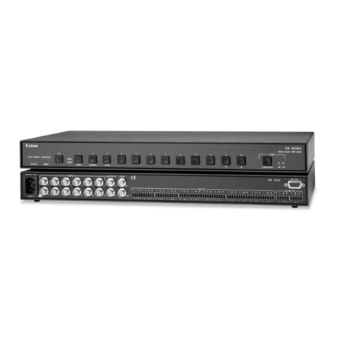
Extron electronics

Extron electronics PVS 407D User manual

Extron electronics SW2 VGA DA2 A User manual

Extron electronics

Extron electronics SW2 VGA DA2 A User manual

Extron electronics SW2 RGBHVcc User manual

Extron electronics

Extron electronics SW2 RGBHVcc User manual

Extron electronics SW2 ARxi User manual

Extron electronics

Extron electronics SW2 ARxi User manual

Extron electronics ISM 1WB User manual

Extron electronics

Extron electronics ISM 1WB User manual

Extron electronics MLS 306 User manual

Extron electronics

Extron electronics MLS 306 User manual

Extron electronics IN1604 DTP User manual

Extron electronics

Extron electronics IN1604 DTP User manual

Extron electronics MTPX Plus Series User manual

Extron electronics

Extron electronics MTPX Plus Series User manual

Extron electronics Matrix 12800 Series User manual
Extron electronics

Extron electronics Matrix 12800 Series User manual

Extron electronics IN1608 xi Series User manual

Extron electronics

Extron electronics IN1608 xi Series User manual

Popular Switch manuals by other brands

Stahl 8060/2-2 operating instructions

Stahl

Stahl 8060/2-2 operating instructions

Pico Macom TSMS-2150X-8AUV Installation and operation manual

Pico Macom

Pico Macom TSMS-2150X-8AUV Installation and operation manual

Microsens Profi Line Modular SERIES quick start guide

Microsens

Microsens Profi Line Modular SERIES quick start guide

PXM PX257-OC user manual

PXM

PXM PX257-OC user manual

Siemens RUGGEDCOM RSG2100PF installation manual

Siemens

Siemens RUGGEDCOM RSG2100PF installation manual

Compex SXP1224B datasheet

Compex

Compex SXP1224B datasheet

PLX Technology PEX 8612-AA RDK Hardware reference manual

PLX Technology

PLX Technology PEX 8612-AA RDK Hardware reference manual

Cisco Catalyst 9200 Series Installing manual

Cisco

Cisco Catalyst 9200 Series Installing manual

AJAX Hub 2 (2G) quick start guide

AJAX

AJAX Hub 2 (2G) quick start guide

Bogen Nyquist NQ-E7020 quick start guide

Bogen

Bogen Nyquist NQ-E7020 quick start guide

fothermo 1010-SWD-1600 user manual

fothermo

fothermo 1010-SWD-1600 user manual

GoMax Electronics PS-5004V user manual

GoMax Electronics

GoMax Electronics PS-5004V user manual

ATEN VS481b user manual

ATEN

ATEN VS481b user manual

Pentair CP-30 user guide

Pentair

Pentair CP-30 user guide

Belkin F1DN104K-3 Configuration manual

Belkin

Belkin F1DN104K-3 Configuration manual

Siemens SIRIUS 3SE51-QV.0 Series Original operating instructions

Siemens

Siemens SIRIUS 3SE51-QV.0 Series Original operating instructions

D-Link DUB-2325 Quick installation guide

D-Link

D-Link DUB-2325 Quick installation guide

Ubiquiti ETHERMAGIC EM-S quick start guide

Ubiquiti

Ubiquiti ETHERMAGIC EM-S quick start guide

manuals.online logo
manuals.online logoBrands
  • About & Mission
  • Contact us
  • Privacy Policy
  • Terms and Conditions

Copyright 2025 Manuals.Online. All Rights Reserved.