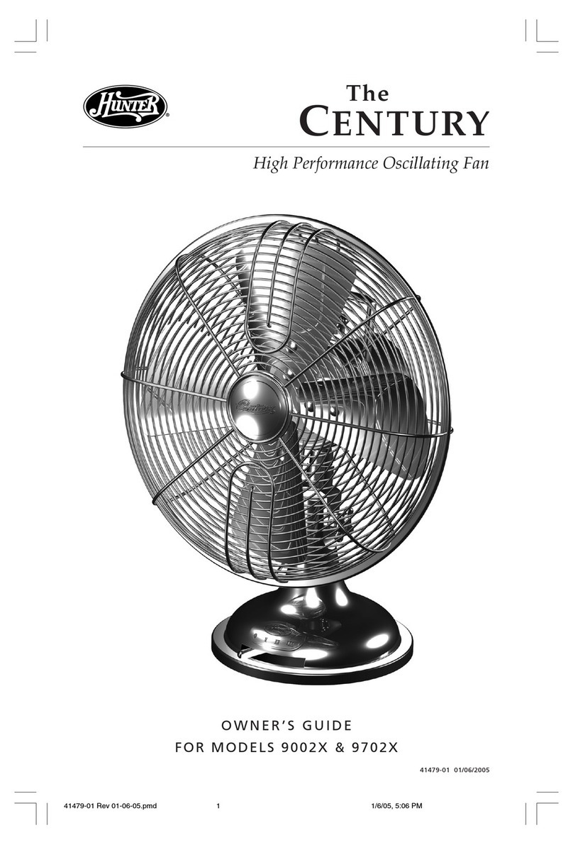
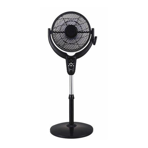
Hunter 90400 User manual

English
Owner’s Guide
High PerformanceHigh Performance
Oscillating Fan
Owner’s Guide
Models
90400
90406
90407
High Performance
61901-01
20210927

IMPORTANT SAFETY INFORMATION
WARNING
CAUTION
When using electrical appliances,
basic precautions should always
electric shock and personal injury:
1. Read all instructions before
using this fan.
2. Improper installation may
shock or personal injury.
3. electric shock, DO NOT use
the unit near windows. Rain
and moisture may create an
electrical hazard.
4. The power plug must be
removed from the power
socket when not in use,
before cleaning, servicing,
maintenance and before
moving to another location.
5. DO NOT put fan in a damp
place or where humidity is
high-such as a bathroom.
6. The fan should be placed on a
to avoid overturning.
7. Use fan only for intended
use, as described in this
instruction manual.
8. To protect against electrical
shock, DO NOT immerse unit,
plug or cord in water or spray
with liquids.
9. Close supervision is necessary
when any appliance is used by
or near children.
11. Do not operate any fan with a
damaged cord or plug. Discard
fan or return to an authorized
service facility for examination
and/or repair.
12. To disconnect, grip plug and
pull from wall outlet. NEVER
yank on cord.
13. ALWAYS use on a dry surface.
14. This product is intended for
household use only and not for
commercial or industrial use.
15. DO NOT operate fan in the
presence of explosive and/or
16. DO NOT place fan or any parts
any other heating appliances.
17. DO NOT use near curtains,
plants, window treatments, etc.
18. This appliance has a grounded
three-prong plug and is suitable
for grounded receptacle use
only.An adapter is available
for connecting three-blade
grounding-type plugs to two-slot
receptacles. The adapter must
be properly grounded. DO NOT
attempt to defeat the purpose
of this safely feature.
19.
20.
The rubber feet on this product
may interact with wood and
cause damage to furniture. Do
Do not run cord under carpeting.
Do not cover cord with throw
rugs, runners, or similar
coverings. Do not route cord
under furniture or appliances.
Arrange cord away from traffic
area and where it will not be
tripped over.
shock, DO NOT use this fan with
any solid-state speed control device.
2 61901-01 R20210927
.01 or any other objects through the
grill when the fan is running.
READ & SAVE THESE INSTRUCTIONS!

Please attach your
receipt or a copy of
your receipt to this manual
for future reference.
WELCOME UNPACKING
As you unpack the fan, save the carton
and packing materials in case you want
to move or ship the unit in the future.
Carefully remove all items from the box.
NOTE: It is best to have someone hold
the box while you lift the fan and the
protective packaging out of the carton.
Make sure all shipping materials are
removed from fan before operating.
Thank you for choosing the Hunter
Millennium™ Table Fan. This manual
gives you complete instructions for
features you will enjoy with your fan:
An attractive design that
enhances any decor
A powerful Hunter motor for
Three speeds to adjust your
comfort level
Before installing your fan, record the
following information for your records
and for warranty assistance.
ModelName_________________
Date Code _________________
Date Purchased ______________
WherePurchased_____________
3
using your fan. Here are some of the
61901-01 R20210927

This appliance is for household
use only and may be plugged into
any 120-volt AC electrical outlet
(ordinary household current). DO
NOT use any other type of outlet.
This unit is suitable for grounded
receptacle use only.
The power cord has a grounded plug
as shown in Figure 1, and must be
used with an electrical outlet that
can accommodate the grounding pin.
If your electrical outlet cannot
accommodate the grounding pin,
then you must purchase an adapter
as shown in Figure 2.
NOTE: The adapters ARE NOT
supplied with this fan. Read, follow,
and save the instructions that are
included with the adapter you choose.
The green grounding lug extending
from the adapter must be connected
to a permanent ground such as a
property grounded outlet box. Do not
use an adapter if your electrical outlet
can accommodate the grounding pin.
GROUNDING
LINE CORD SAFETY TIPS
1. NEVER pull or yank on the
cord or the appliance.
2.
and guide it into the outlet.
3. To disconnect the appliance,
grasp the plug and remove it
from the outlet.
4. Before each use, inspect
the line cord for cuts and/or
abrasion marks. If any are
found, the appliance should
be serviced and the line cord
replaced. Please return it
to our Service Department
or to an authorized service
representative.
5. NEVER wrap the cord tightly
around the appliance, as this
could place undue stress on
the cord where it enters the
appliance and could cause it
to fray and break.
6. DO NOT operate appliance
if the line cord shows any
damage, if the appliance
works intermittently or stops
working entirely.
WARNING
4 61901-01 R20210927
Figure 1
Fi 1
Grounded
Plug
Grounding Pin Grounded Outlet
Box Cover
Figure 2
Fi
2
Grounded Outlet
Box Cover
Metal
Screw
Adapter
Grounding
Means

FUSED PLUG
5
Figure 3
Figure 4
Figure 5
Fuse Replacement:
1.
2. Slide the door on top of the plug
3. Carefully remove the fuse from
the clips holding it on the top and
Warning! Electrical Hazard! Only
replace with a fuse type and rating
matching what was removed from the
product. If the product fails a second time,
immediately unplug it and contact our
technical support at 1-888-880-3267.
4. Gently push the fuse back into
the pins that will hold it in place.
Note: If the fuse is not seated properly,
the unit will not function.
5.
box in the plug.
Grasp plug and remove from the
receptacle or other outlet device.
Do not unplug by pulling on cord.
Locate the door on top of the plug.
Figure 3.
bottom. Risk of fire. Replace fuse
only with 5 Amp, 125 Volt fuse.
Figure 5.
Slide the door back over the fuse
towards the blades. Figure 4.
61901-01 R20210927
This product uses overload protection
(fuse). A blown fuse indicates an overload
or short-circuit situation. If the fuse blows,
unplug the product from the outlet. Discard
product if the attachment plug is damaged.
To reduce the risk of fire, electric shock
and personal injury, DO NOT remove,
replace, repair or tamper with the originally
supplied plug. If the fan does not function
properly, it may be due to the safety
device incorporated in this plug.
If the fuse fails, it is generally due to a
short circuit or circuit overload. Replace
the fuse as per the instructions below
(follow product marking for proper fuse
rating) and check the product. If the
replacement fuse fails, a short-circuit
may be present and immediately
unplug the unit and contact our
technical support department for
assistance.
6. Plug the fan back in and resume
use.
Risk of fire. Do not replace attachment
plug. Contains a safety device (fuse) that
should not be removed. Discard product
if the attachment plug is damaged.

NOTE: It is best to have someone hold
the box while lifting the fan and protective
packaging out of the carton. Make sure all
shipping materials are removed from fan
before operating.
Note: The grill ring may be attached to
the rear grill for shipping purposes. If so,
remove the grill ring by loosening the grill
ring screw.
Note: One of the grill mounting screws
will have a star washer for grounding
purpose. The other 3 screws will not have
a washer.
UNPACKING
6
As you unpack the fan, save the carton
and packing materials in case you want to
move or ship the unit in the future.
Carefully remove all items from the box.
1. Remove the four rear grill mounting
screws from the motor housing. Figure 6.
2. Make sure the rear grill is positioned so
that three of the grill lines are completely
between the top tabs, Figure 7. Then
place the rear grill against the motor
housing, and line up the four tabs on the
back of the grill to the four screw holes
on the front of the motor.
3. To attach the rear grill to the motor
housing partially install the four grill
mounting screws. Tighten all four
screws. Figure 8.
4. Loosen the screw on the back of the
blade assembly. Figure 9a. Slide the
blade assembly onto the motor shaft.
Figure 9.
5. Tighten the screw on the blade assembly
to secure it to the motor. Make sure that
the end of the screw is positioned within
the notch on the shaft. Figure 10.
GRILL ASSEMBLY:
61901-01 R20210927
Figure 6
Grill
Mounting
Screw
Figure 7
Grill Lines
Top Tabs
123
Figure 8
Caution: Be sure to tighten the screw on
the back of the fan blade to the flat part
of the motor shaft.

Figure 9
Motor
Fan Blade
9a
Figure 11
Figure 10
Notch
Rear Grill
Front Grill
Hunter Logo
Figure 12
Grill
Ring
Screw
Figure 13
Screw
GRILL ASSEMBLY CONT.
7
6. Remove the grill ring from the front grill
by loosening the screw holding it
together.
7. Place the front grill against the rear grill
so that the Hunter logo faces right side
up and push together until the tabs on
the grills hold them together. Figure 11.
8. Expand the grill ring by loosening the
screw that secures it. Figure 12.
9. Slide the grill ring over both front and
rear grills turning the ring so that the
screw is on the bottom. Figure 12.
10. Tighten the screw to secure the grill
ring over both the front and rear grill.
Figure 13.
61901-01 R20210927

OPERATION
This appliance is for household use only.
1.
surface where it cannot fall or
be pulled by the cord.
2. Plug the fan into a grounded
120-volt AC electrical outlet
(ordinary household current).
DO NOT use any other type of
outlet. Make sure that the rated
voltage of the fan is the same
as the power source before
plugging it into the power
source.
3. Turn the fan “ON” or “OFF”
by moving the power/speed
lever. The power should always
be OFF before unplugging the
fan.
4. To select the speed, move the
power/speed lever from OFF to
the desired speed setting: O (off),
I (Low), II (Medium), III (High).
5. To control the upward and
loosen the screw on the side of
the fan housing neck. Adjust to
the desired angle and tighten
the screw.
Handle
Oscillation Knob
Motor Housing
Up/Down
Adjustment Screw
Base
Power/Speed
Lever
8
6. To make the fan oscillate, push
knob up. The oscillation knob is
the oscillation knob down. To
located on the top of the fan
stop oscillating, pull the oscillation
housing, near the handle.
Figure 14
61901-01 R20210927

MAINTENANCE
This fan is permanently lubricated and
will not require additional lubrication (oil)
for the life of the fan.
This fan requires little maintenance
and contains no user serviceable parts.
TO CLEAN:
outlet. Wipe off excess dust
2. To ensure adequate air
circulation to the motor, keep
vents located at the rear of
the motor housing free from
dust accumulation. A vacuum
cleaner hose can be used to
clean these vents.
3. DO NOT immerse the fan in
water or any other liquid.
CLEANING GRILL AND BLADE:
1. Turn the fan off and unplug
from the electrical outlet.
2. Disassemble grills by carefully
removing the screw on the
3. Remove the ring.
4. Use a dry or slightly damp lint
free cloth to clean the fan.
5. Use a soft, slightly damp cloth
to wipe the remaining fan parts.
6. DO NOT allow water or any
other liquid to get into the motor
housing or base.
7. Reassemble the fan after
blades and grills have dried
completely. Align the grills,
replace the ring, and replace
the screw.
8. DO NOT plug fan into an
electrical outlet until it has been
fully reassembled.
Front
Grill
Ring
Base
Power/Speed
Lever
Blade
Screw
Back
Grill Handle
Oscilation
Knob
Motor
Housing
Up/Down
Adjustment
Screw
9
is needed.
bottom of the ring. See Figure 15.
1. Before cleaning, turn the fan
with a lintfree cloth.
off and unplug from electrical
61901-01 R20210927
Figure 15

STORAGE TROUBLESHOOTING
1. Disassemble and clean fan
before storing.
2. Keep the original packaging for
the purpose of storing the fan.
3. ALWAYS store the fan in a
dry place.
4. NEVER store the fan while it is
still plugged in.
5. NEVER wrap the cord tightly
around the fan.
6. DO NOT put any stress on the
cord where it enters the fan, as
it could cause the cord to break.
PROBLEM
Fan will not oscillate.
SOLUTION
housing to activate oscillation.
PROBLEM
SOLUTION
TECHNICAL SUPPORT
Loosen the screw on the side of the
fan neck. Adjust to the desired
angle and tighten the screw.
10
.nafehtfoelgnaehttsujdatonnaC
rotomfopotnobonkehtnwodhsuP
If you need any assistance with setup,
operation, or parts for your new Hunter
Portable Fan, please call us. Our
technical support staff is ready to help!
We are open 24 hours a day, 7 days a
week.
You may also reach us online at
www.HunterHomeComfort.com.
An electronic copy of this user manual
can also be obtained online at
www.HunterHomeComfort.com.
1-888-880-3267 (FANS)
61901-01 R20210927

WARRANTY
following limited warranty to the user
or consumer purchaser of this Hunter
Portable fan:
the date of sale to you due to a defect
in material or workmanship, labor
to repair the defect will be provided
free of charge at our nearest service
center or our Service Department
be responsible for labor costs after
limited warranty applies only to the
motor itself, and does not apply to
electronic controls such as remote
controls, remote control receivers or
transmitters used in conjunction with
the motor. These electronic control
items are included in the one year
If any part of your Hunter Portable
Fan other than the motor fails at any
sale to you due to a defect in material
or workmanship, we will repair or, at
our option, replace the defective part
free of charge for parts and labor
performed at our nearest service
center or at our Service Department
IF THE USER OR CONSUMER
PURCHASER CEASES TO OWN THE
FAN, THIS WARRANTY AND ANY
IMPLIED WARRANTY WHICH THEN
REMAINS IN EFFECT, INCLUDING
BUT NOT LIMITED TO ANY IMPLIED
WARRANTY OF MERCHANTABILITY
PURPOSE, ARE VOIDED. NO
WARRANTY, EXPRESSED ORIMPLIED,
INCLUDING ANY WARRANTY OF
MERCHANTABILITY OR FITNESS FOR
A PARTICULAR PURPOSE, IS MADE
IN RESPECT TO THE GLASS GLOBES
OR LIGHT BULBS OR THE FINISH
ON ANY METAL PORTION OF THE
FAN. THIS WARRANTY IS IN LIEU OF
ALL OTHER EXPRESS WARRANTIES.
THE DURATION OF ANY IMPLIED
WARRANTY, INCLUDING, BUT
WARRANTY OF MERCHANTABILITY
OR FITNESS FOR A PARTICULAR
PURPOSE, IN RESPECT TO ANY
HUNTER FAN MOTOR OR OTHER
FAN PART, IS EXPRESSLY LIMITED
TO THE PERIOD OF THE EXPRESS
WARRANTY SET FORTH ABOVE FOR
SUCH MOTORS AND OTHER PARTS.
This warranty is voided if your
Hunter Fan is not purchased and
used in the USA.
This warranty excludes and does
not cover defects, malfunctions or
failures of any Hunter Portable fan
which were caused by repairs by
persons not authorized by us, use of
parts or accessories not authorized
by us, mishandling, improper
damage to the Hunter Portable
fan while in your possession,
or unreasonable use, including
failure to provide reasonable and
necessary maintenance.
To obtain servicing, contact the
nearest Hunter authorized service
OR FITNESS FOR A PARTICULAR center or the Hunter Home Comfort
in Kennesaw, Georgia.
in Kennesaw, Georgia. You will NOT LIMITED TO ANY IMPLIED
11
Hunter Home Comfort makes the
If your Hunter Portable Fan motor
time within one year after the date of
limited warranty below.
61901-01 R20210927

fan to us. If we authorize you to
ship it to us, you will be
responsible for all insurance and
freight or other transportation
charges to our factory service
center. We will return your Hunter
Fan freight prepaid. Your portable
fan should be properly packed
to avoid damage in transit since
we will not be responsible for any
such damage. Proof of purchase is
required when requesting warranty
service. The purchaser must present
sales receipt or other document that
establishes proof of purchase.
FOR CONSEQUENTIAL OR
INCIDENTAL DAMAGES.
SOME STATES DO NOT ALLOW
LIMITATIONS ON HOW LONG
AN IMPLIED WARRANTY
LASTS OR THE EXCLUSION OR
LIMITATION OF INCIDENTAL OR
CONSEQUENTIAL DAMAGES
SO THE ABOVE LIMITATION MAY
NOT APPLY TO YOU.
SPECIFIC LEGAL RIGHTS AND
YOU MAY ALSO HAVE OTHER
RIGHTS WHICH VARY FROM
STATE TO STATE.
Service Department, 980 Cobb
Place Boulevard NW, Suite 100, IN NO EVENT SHALL HUNTER
Kennesaw, GA 30144. Please
contact us before shipping your
980 Cobb Place Boulevard NW, Suite 100, Kennesaw, GA 30144
Hunter is a trademark of the Hunter Fan Company and
is used under license to Hunter Home Comfort.
Printed in China
HOME COMFORT BE LIABLE
12
THIS WARRANTY GIVES YOU
61901-01 R20210927

Alto RendimientoAlto Rendimiento
Modelos
90400
90406
Alto Rendimiento
Español
61901-02
Ventilador de Oscilación
Manual del Propietario
90407
20210927

INFORMACIÓN IMPORTANTE DE SEGURIDAD
ADVERTENCIA
Para reducir el riesgo de fuego
o choque eléctrico, NO use este
ventilador con ningún tipo de
dispositivo de control de velocidad de
estado sólido.
PRECAUCION
Cuando se usan aparatos eléctricos,
se deben tomar siempre ciertas
precauciones para reducir el riesgo
de fuego, choque eléctrico y lesiones
personales.
1. Lea todas las instrucciones antes
de usar este ventilador.
2. Una instalación incorrecta podrá
resultar en un riesgo de fuego,
choque eléctrico o lesiones
personales.
3. Para evitar el riesgo de fuego y
choque eléctrico, NO use la unidad
cerca de ventanas. La lluvia y la
humedad pueden crear un peligro
eléctrico.
4. El enchufe eléctrico se debe retirar
del tomacorriente de la pared
cuando no se use el ventilador,
antes de limpiarlo, darle servicio o
mantenimiento y antes de moverlo
a otro lugar.
5. NO coloque el ventilador en un
lugar mojado ni donde la humedad
sea alta, como en un baño.
6. El ventilador se debe colocar sobre
una superficie o mesa plana y
estable, para evitar que se caiga o
se vuelque.
7. Use el ventilador solamente para
el fin con el que ha sido diseñado,
como se describe en este manual
de instrucciones.
8. Para protección contra un choque
eléctrico, NO sumerja esta unidad,
el enchufe o el cordón eléctrico en
agua ni lo rocíe con líquidos.
9. Una supervisión cercana es
necesaria cuando cualquier aparato
es usado por niños o cerca de ellos.
10. NUNCA inserte sus dedos, lápices
o cualquier otro objeto a través de
la rejilla cuando el ventilador está
en operación.
2
Lea y Guarde Estas Instrucciones
11. NO opere un aparato eléctrico
que tenga un cordón o enchufe
eléctrico. Deseche el ventilador o
devuélvalo a una instalación de
servicio autorizada para ser
revisado o reparado.
12. Para desconectar el ventilador,
agarre el enchufe y sáquelo del
tomacorriente de la p
13. SIEMPRE use el ventilador sobre
un superficie seca.
14. Este producto ha sido diseñado
para uso residencial solamente y
no para uso comercial ni industrial.
15. NO opere el ventilador en la
presencia de explosivos ni de
vapores inflamables.
16. NO coloque el ventilador ni
ninguna pieza cerca de una llama
abierta, cocina o cualquier otro
aparato que produzca calor.
20. No coloque el cable debajo de
las alfombras. No cubra el cable
con alfombras, tapetes ni
coberturas similares. No coloque
el cable debajo de muebles o
electrodomésticos. Coloque el
cable lejos del área de tránsito y
donde no pueda causar tropiezos.
61901-02 R20210927
18. Este aparato tiene un enchufe
de tres clavijas para conexión a
tierra y sólo se puede usar en un
tomacorriente conectado a tierra.
Existen adaptadores disponibles
para conectar un enchufe de tres
clavijas a un tomacorriente de
dos ranuras. Estos adaptadores
deben estar conectados a tierra
correctamente. NO trate de usar
un adaptador que elimine la
seguridad de una buena conexión
a tierra.
19. La base de plástico de este
producto puede interactuar con la
madera y causar daños a los
muebles. No lo coloque sobre
muebles de madera fina.
17. NO use el ventilador cerca de
cortinas, plantas, tratamientos
para ventanas, etc.

o una copia de su recibo
a este manual para
referencia futura.
BIENVENIDO DESEMPAQUE
Muchas gracias por seleccionar
de Hunter. Este manual contiene
instrucciones completas para usar
su ventilador. Estas son algunas de
las características que disfrutará
con su ventilador:
'LVHxRDWUDFWLYRTXHUHDOL]DOD
decoración de cualquier lugar.
3RGHURVRPRWRU+XQWHUSDUDXQ
Tres velocidades para ajustar el
para usted.
Antes de instalar su ventilador,
anote la información siguiente para
sus récords y para asistencia con
la garantía.
Código de fecha
Fecha de compra
Lugar donde lo compró
Cuando desempaque el ventilador,
guarde la caja y los materiales
protectores de empaque, en caso
de que quiera mover o embarcar la
unidad en el futuro.
Saque todas las partes de la caja con
mucho cuidado.
NOTA: Es mejor que alguien
sostenga la caja mientras usted
levanta el ventilador y los materiales
protectores fuera de la caja.
Asegúrese de que todos los
materiales protectores hayan sido
retirados del ventilador antes de
ponerlo en funcionamiento.
3
Nombre del modelo
________________
________________
___________
______________
_
el ventilador de mesa Millennium™
61901-02 R20210927

Esta unidad es adecuada para
uso en tomas a tierra solamente.
El cable de alimentación tiene un
conector de puesta a tierra como se
muestra en la Figura 1 y debe ser
usado con una toma de corriente que
pueda adaptarse al pasador para
conexión a tierra. Si el tomacorriente
eléctrico no puede alojar la clavija de
conexión a tierra, deberá comprar un
adaptador como se muestra en la
Figura 2. NOTA : Los adaptadores
NO son suministrados con este
ventilador. Lea, cumpla y guarde las
instrucciones que se incluyen con el
adaptador que elija. El terminal verde
que se extiende del adaptador se
debe conectar a una tierra
permanente, tal como una caja
eléctrica conectada a tierra
correctamente. No use un adaptador
si su toma de corriente puede
adaptarse al pasador para conexión a
tierra.
PUESTA A TIERRA
ADVERTENCIA
4
Este artefacto está destinado
solamente para uso doméstico y
puede conectarse en cualquier toma
de 120 voltios de corriente alterna
(salida típica doméstica). NO use
ningún otro tipo de salida.
1. NUNCA tire o jale bruscamente del
cordón del artefacto.
2. Para introducir el enchufe, tómelo
firmemente y colóquelo dentro de la
toma de corriente.
3. Para desconectar el artefacto, tome
el enchufe y retírelo de la toma de
corriente.
SUGERENCIAS DE SEGURIDAD
PARA EL CORDÓN DE
ALIMENTACIÓN
4. Antes de cada uso, verifique que el
cordón de alimentación no tenga cortes
ni marcas de desgaste. Si encuentra
algún corte o alguna marca, debe revisar
el artefacto y reemplazar el cordón de
alimentación. Devuelva el artefacto a
nuestro Departamento de servicio o a un
representante de servicio autorizado.
5. NUNCA enrolle el cordón en forma
ajustada alrededor del artefacto, ya que
podría aplicarse una tensión indebida al
mismo en el punto de ingreso al artefacto,
lo que podría causar que el cordón se
pele y se rompa.
6. NO opere el artefacto si el cordón de
alimentación muestra algún daño, si
funciona en forma intermitente o si deja
de trabajar por completo.
Figura 1
Fi 1
Figura 2
Fi
2
Adaptador
Medio de Cubierta de la
Tornillo
Conector puesto
a tierra
Pin para puesta
a tierra Cubierta de la
caja de salida
de metal
puesta caja de salida
a tierra
61901-02 R20210927

Este producto cuenta con protección
contra sobrecarga (fusible). Un fusible
quemado indica una situación de
sobrecarga o cortocircuito. Si el fusible
se quemara, desenchufe el producto
del tomacorriente. Deseche el producto
si el enchufe está dañado. Para reducir
el riesgo de incendio, choque eléctrico
o lesiones personales, NO retire,
reemplace, repare ni manipule el
enchufe suministrado originalmente. Si
el ventilador no funciona
correctamente, puede ser debido al
dispositivo de seguridad incorporado
en este enchufe.
4. Presione suavemente el fusible
hacia los pines que lo mantendrán en
su posición.
5. Deslice la tapa nuevamente sobre la
caja del fusible en el enchufe.
6. Enchufe nuevamente el ventilador y
reanude su uso. Riesgo de incendio. No
reemplace el enchufe de conexión.
Contiene un dispositivo de seguridad
(fusible) que no debe retirarse. Deseche
el producto si el enchufe está dañado.
Nota : Si el fusible no está asentado
adecuadamente, la unidad no
funcionará.
Si el fusible falla, por lo general, se
debe a un cortocircuito o a una
sobrecarga. Reemplace el fusible
según las instrucciones de abajo (siga
los marcados del producto para
seleccionar el fusible de valor
adecuado) y revise el producto. Si el
fusible de reemplazo no sirve, puede
haber un cortocircuito, desenchufe
inmediatamente la unidad y contacte
al departamento de soporte técnico
para asistencia.
¡Advertencia! ¡Riesgo eléctrico! Sólo
reemplace con un tipo de fusible y
capacidad iguales a las del producto
retirado. Si el producto falla en la
segunda vez, inmediatamente
desconéctelo y contacte a nuestro
soporte técnico al 1-888-880-3267.
1. Tome el enchufe y retírelo del
tomacorriente o de donde esté
enchufado. No desenchufe jalando del
cable. Ubique la tapa de acceso en la
parte superior del enchufe. Figura 3.
2. Deslice la tapa hacia las espigas.
Figura 4.
3. Retire cuidadosamente el fusible de
las pinzas que lo sostienen en la parte
superior e inferior. Reemplace el fusible
solamente con uno de 5 Amperios y
125 Voltios. Figura 5.
ENCHUFE CON FUSIBLE
5
Figura 3
Reemplazo del fusible :
5
Figura 4
Figura
61901-02 R20210927

DESEMBALAJE
6
Cuando desembale el ventilador, guarde
la caja y los materiales de embalaje para
el caso de que desee mover o embarcar
la unidad posteriormente. Retire
cuidadosamente todos los artículos de la
caja.
5. Apriete el tornillo en el conjunto de
aspas para asegurarlo al motor.
Asegúrese de que el extremo del tornillo
está colocado dentro de la muesca del
eje. Figura 10.
61901-02 R20210927
Figura 6
Tornillos de
montaje de
la parrilla
Figura 7
Líneas de
la rejilla
Pestañas
superiores
123
Figura 8
NOTA : Es mejor que alguna persona
sostenga la caja mientras usted levanta
el ventilador y la envoltura de protección
fuera de la caja de cartón. Asegúrese de
que todos los materiales de despacho
sean retirados del ventilador antes de su
operación.
ENSAMBLAJE DE LA REJILLA:
Nota : Puede conectar el anillo de la
parrilla a la parrilla trasera por motivos de
embalaje. Si es así, retire el anillo de la
parrilla aflojando el tornillo del anillo de la
parrilla.
Nota : Uno de los tornillos de montaje de
la rejilla tendrá una arandela de estrella
para la conexión a tierra. Los otros 3
tornillos no tendrán una arandela.
Precaución : Al apretar el tornillo en la
parte posterior del aspa del ventilador,
asegúrese de apretarlo sobre la parte
plana del eje del motor.
1. Retire los cuatro tornillos de montaje
de la parrilla del alojamiento del motor.
Figura 6.
3. Para ensamblar la rejilla posterior al
alojamiento del motor instale parcialmente
los cuatro tornillos de montaje de parrilla.
Apriete los cuatro tornillos. Figura 8.
4. Afloje el tornillo en la parte posterior
del conjunto de las aspas. Figura 9a.
Deslice el conjunto de las aspas en el eje
del motor. Figura 9.
2. Asegúrese de que la parrilla está
posicionada de modo que las tres líneas
de la parrilla estén completamente entre
las pestañas superiores, Figura 7. Luego
coloque la rejilla posterior contra el
alojamiento del motor, y alinee las 4
pestañas en la parte posterior de la rejilla
con los 4 agujeros para tornillos de la
parte frontal del motor.

Figura 9
Motor
9a
Figura 11
Figura 10
Muesca
Rejilla
posterior
Rejilla frontal
Logotipo de
Hunter
Figura 12
Anillo de
la rejilla
Tornillo
Figura 13
Tornillo
ENSAMBLAJE DE LA REJILLACONT.
7
6. Retire el anillo de la rejilla de la rejilla
frontal aflojando el tornillo que lo sostiene.
7. Coloque la rejilla frontal contra la rejilla
posterior para que el logotipo de Hunter
quede directamente hacia arriba y
presione ambas hasta que las pestañas
de las rejillas se acoplen. Figura 11.
8. Expanda el anillo de la rejilla el tornillo
que los une. Figura 12.
9. Deslice el anillo de la parrilla sobre las
parrillas delantera y trasera girando el
anillo para que el tornillo quede en la
parte inferior. Figura 12.
10. Apriete el tornillo para asegurar el
anillo de la rejilla sobre las rejillas frontal
y trasera. Figura 13.
61901-02 R20210927
Aspa del
ventilador

OPERACIÓN
8
2. Enchufe el ventilador en un
tomacorriente eléctrico conectado
a tierra de 120 voltios c.a. (voltaje
residencial normal). NO use ningún
otro tipo de tomacorriente. Asegúrese
de que el voltaje de operación del
ventilador sea el mismo que el del
tomacorriente antes de enchufar el
cordón eléctrico.
3. Encienda (“ON”) o apague
(“OFF”) el ventilador, deslizando el
interruptor de control de encendido
y velocidad hacia la derecha o
la izquierda. El ventilador debe
estar siempre apagado antes de
desenchufarlo del tomacorriente.
4. Para seleccionar la velocidad,
mueva el control de encendido y
velocidad desde la posición “OFF”
hasta la velocidad deseada:
5. Para controlar la dirección del
un lado del cuello de la caja del
ventilador. Ajuste el aparato en el
ángulo deseado y apriete el tornillo.
6. Para que el ventilador oscile,
oprima la perilla de oscilación hacia
abajo. Para detener la oscilación, tire
de la perilla hacia arriba. La perilla de
oscilación está ubicada en la parte
superior de la caja del motor, cerca
del asa.
Este ventilador es para uso
residencial solamente.
1. Coloque el ventilador sobre una
donde no se pueda caer ni ser tirado
por el cordón.
Figura 14
O (apagado), I (baja), II (media),
y III (alta).
Asa
Perilla de
Oscilación
Caja del
Motor
Tornillo de Ajuste Hacia
Base
Palanca de encendido/velocidad
Arriba y Hacia Abajo
61901-02 R20210927
Other manuals for 90400
2
This manual suits for next models
2
Table of contents
Languages:
Other Hunter Fan manuals

Hunter
Hunter 51097 User manual

Hunter
Hunter 9101X User manual

Hunter
Hunter 52228 User manual

Hunter
Hunter 28671 Manual

Hunter
Hunter Hunter Ceiling Fan User manual

Hunter
Hunter 53069 Instruction manual

Hunter
Hunter 20168 Instruction manual

Hunter
Hunter 23979 Manual

Hunter
Hunter 28110 User manual

Hunter
Hunter 22720 Manual

Hunter
Hunter Kensie 50642 User manual

Hunter
Hunter 42890-01 Instruction manual
Hunter
Hunter Hardaway User manual

Hunter
Hunter Stingray User manual

Hunter
Hunter Acumen 59409 User manual

Hunter
Hunter 21729 Manual

Hunter
Hunter Seawall User manual

Hunter
Hunter 21538 User manual

Hunter
Hunter 21728 Manual

Hunter
Hunter 51736 User manual