Bayside LAGOON User manual
V1.0 Muti –EU WS (09/2018)
BAYSIDE
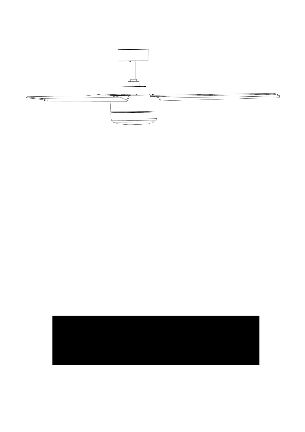
LAGOON
CEILING FAN
INSTALLATION
OPERATION
MAINTENANCE
WARRANTY INFORMATION
CAUTION
READ INSTRUCTIONS CAREFULLY FOR SAFE
INSTALLATION AND FAN OPERATION.

Lagoon Fan Installation Instructions
1 | P a g e
CONTENTS
GB
Installation instruction manual ...........................................................................................2
D
Installationsanleitung ........................................................................................................11
F
Guide d’installation............................................................................................................20
E
Manual de instrucciones de instalación.............................................................................28
I
Manuale delle istruzioni di installazione............................................................................36
NL
Installatiehandleiding.........................................................................................................44
EL
Εγχειρίδιο οδηγιών εγκατάστασης ....................................................................................52

Lagoon Fan Installation Instructions
2 | P a g e
THANK YOU FOR PURCHASING
Thank you for purchasing this quality Bayside product. To ensure correct function and safety, please read
and save all instructions before using the product.
SAFETY PRECAUTIONS
1. In Europe: This appliance can be used by children aged from 8 years and above and persons with
reduced physical, sensory or mental capabilities or lack of experience and knowledge if they have
been given supervision or instruction concerning the use of the appliance in a safe way and
understand the hazards involved. Cleaning and maintenance shall not be undertaken by children
without supervision.
2. In Australia: The appliance is not intended for use by persons (including children) with reduced
physical, sensory or mental capabilities, or lack of experience and knowledge, unless they have been
given supervision or instruction concerning the use of the appliance by a person responsible for their
safety.
3. Children should be supervised to ensure that they do not play with the appliance.
4. An all-pole disconnection switch must be incorporated into the fixed wiring, in accordance with local
wiring rules.
IN AUSTRALIA
WARNING:
FOR SAFE USE OF THIS FAN AN ALL-POLE DISCONNECTION
MUST BE INCORPORATED INTO THE FIXED WIRING IN
ACCORDANCE WITH THE WIRING RULES.
As outline in clause 7.12.2 of AS/NZS 60335-1 for meeting the
minimum electrical safety of this standard.
Please note warranty will be void if installation is without a means for
an all-pole disconnection incorporated in the fixed wiring in
accordance with the wiring rules.
Lagoon Fan Installation Instructions
3 | P a g e
Example: If a fan is connected to a circuit that can be isolated via an
all-pole safety switch at the switchboard, then this is considered to be
an all-pole disconnection to the ceiling fan electrical circuit, meeting
the requirements of clause 7.12.2 of AS/NZS 60335.1.
A single-pole switch on the active of the receiver input of remote
control must also be included in the wiring, and located the
same room as the ceiling fan.
5. Do not dispose of electrical appliances as unsorted municipal waste, use separate collection
facilities. Contact your local government for information regarding the collection systems available. If
electrical appliances are disposed of in landfills or dumps, hazardous substances can leak into the
ground water and get into the food chain, damaging your health and well-being.
6. The structure to which the fan is to be mounted must be capable of supporting a weight of 30kg.
7. The fan should be mounted so that the blades are at least 2.3 m above the floor in Europe or 2.1 m
above the floor in Australia.
8. This fan is suitable for indoor, alfresco and coastal areas where the fan is fully undercover with a
minimum of 1 walls. This fan is not waterproof. When installed in an alfresco or coastal area, the
ceiling fan must be positioned in a location protected from water, wind and dust. Exposure to these
elements will void the warranty. Mounting the fan in a situation where it is subject to water or moisture
is dangerous.
9. Only a licensed electrician should execute the installation.

Lagoon Fan Installation Instructions
4 | P a g e
BEFORE INSTALLATION
Unpack your ceiling fan carefully. Remove all parts and hardware. Examine all parts, you should have
the following:
Fan without light
Fan with light
1
Mounting bracket x 1
1
Mounting bracket x 1
2
Pre-assembled fan motor, down rod and canopy
x 1
2
Pre-assembled fan motor, down rod and
canopy x 1
3
Blades x 3
3
Blades x 3
4
Wood screw x 2
4
GX53 lamp x 1
5
Motor screws for blades x 10
5
Wood screw x 2
6
Balancing kit x 1 set
6
Motor screws for blades x 10
7
Wall switch x 1 set
7
Balancing kit x 1 set
8
Wall switch x 1 set
Fig. 1

Lagoon Fan Installation Instructions
5 | P a g e
INSTALLING THE MOUNTING BRACKET
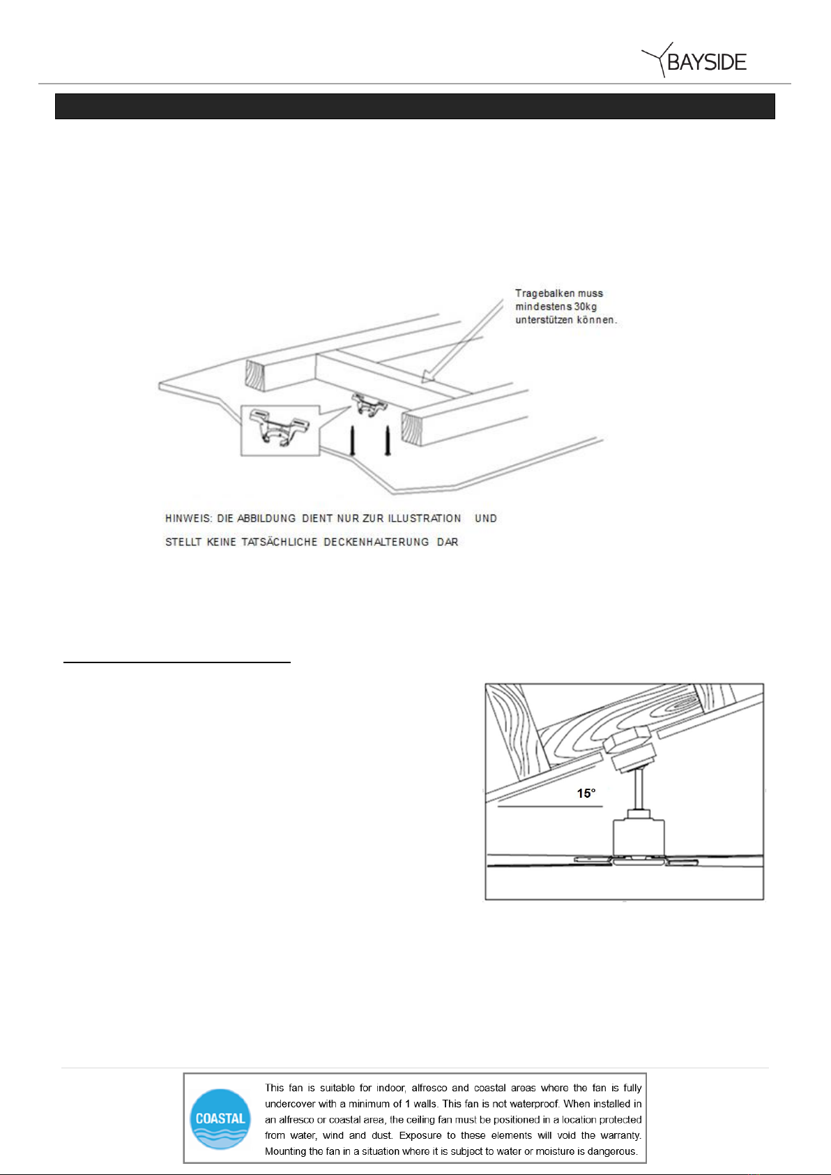
The ceiling fan must be installed in a location so that the blades are spaced 300mm from the tip of the blade
to the nearest objects or walls.
Secure the hanging bracket to the ceiling joist or structure that is capable of carrying a load of at least 30kg,
with two long screws provided. Ensure at least 30mm of the screw is threaded into the support.
NOTE: The bracket screws provided are for use with wooden structures only. For structures other than
wood, the appropriate screw type MUST be used.
Angled ceiling Installation
This fan hanging system supports a maximum 15 degree angled
ceiling installation.
Fig. 2
Fig. 3

Lagoon Fan Installation Instructions
6 | P a g e
HANGING THE FAN
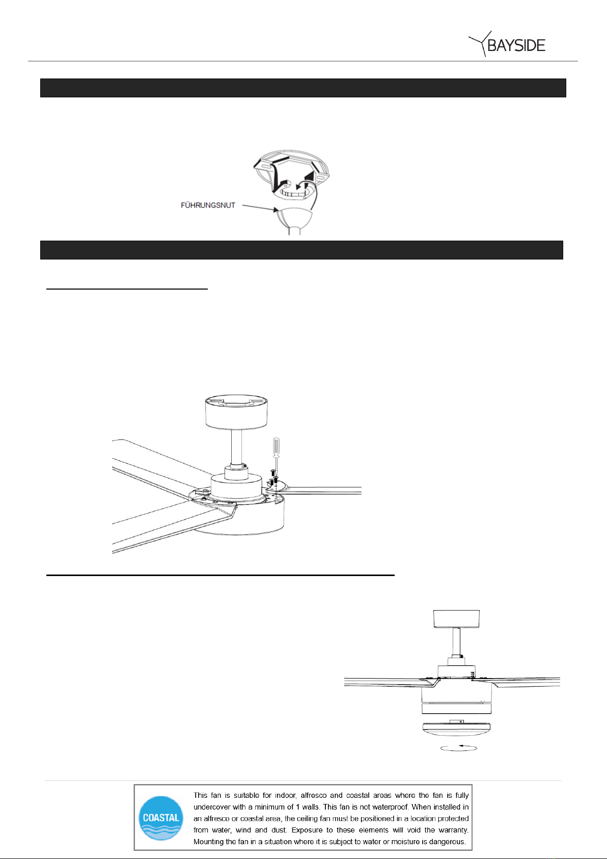
Lift the fan assembly onto the mounting bracket. Ensure the registration slot (A) of the hanger ball is
positioned on the stopper (B) of the mounting bracket (C) to prevent the fan from rotating when in
operation. (Fig.4)
INSTALLING THE FAN
Blade attachment
Secure the blade on the motor by using 3 screws to tighten it, ensuring they are tightened simultaneously.
(Take care not to over tighten as this can damage blades)
Once completed, repeat the process on the remaining blades.
Light kit installation (For fan with light)
Install the globe (included, Max. 23W, GX53) in the lamp holder.
Fig. 4
Fig. 5
Fig. 6
Lagoon Fan Installation Instructions
7 | P a g e
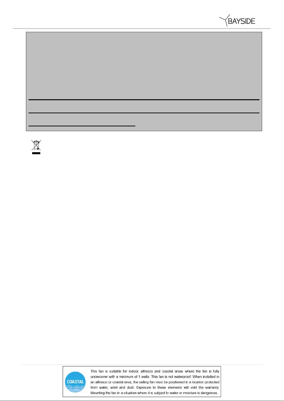
ELECTRICAL WIRING DIAGRAM
WARNING: FOR YOUR SAFETY ALL ELECTRICAL CONNECTIONS MUST BE UNDERTAKEN BY A
LICENSED ELECTRICIAN.
NOTE: AN ADDITIONAL ALL POLE DISCONNECTION SWITCH MUST BE INCLUDED IN THE FIXED
WIRING.
NOTE: Wiring diagram includes the light kit wiring. The light wiring diagram and switch is omitted
when no light kit is used with the ceiling fan.
USE WITH WALL SWITCH WIRING DIAGRAM:
USE WITH REMOTE WIRING DIAGRAM: (REMOTE sold separately)
1/ Remote without plugs
Fig. 6
Fig. 7

Lagoon Fan Installation Instructions
8 | P a g e
2/ Remote with plugs
FINISHING THE INSTALLATION
After completing the electrical connection at the mounting bracket terminal block, connect the ceiling
fan wiring via the quick connector plug.
Cover the mounting bracket with the canopy. Ensure all electrical wiring is tucked inside the canopy
and that the wires are not damaged during this step. Secure the canopy to the hanger bracket using
the screws provided.
Fig. 9
Fig. 8
Lagoon Fan Installation Instructions
9 | P a g e
USING YOUR CEILING FAN
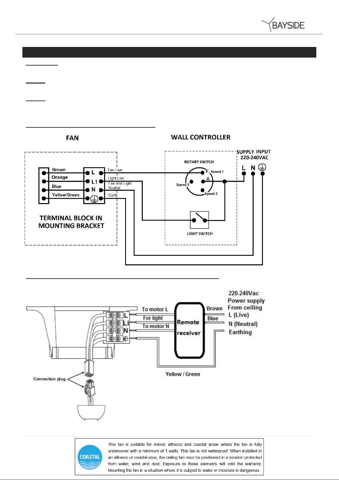
FAN WALL CONTROL
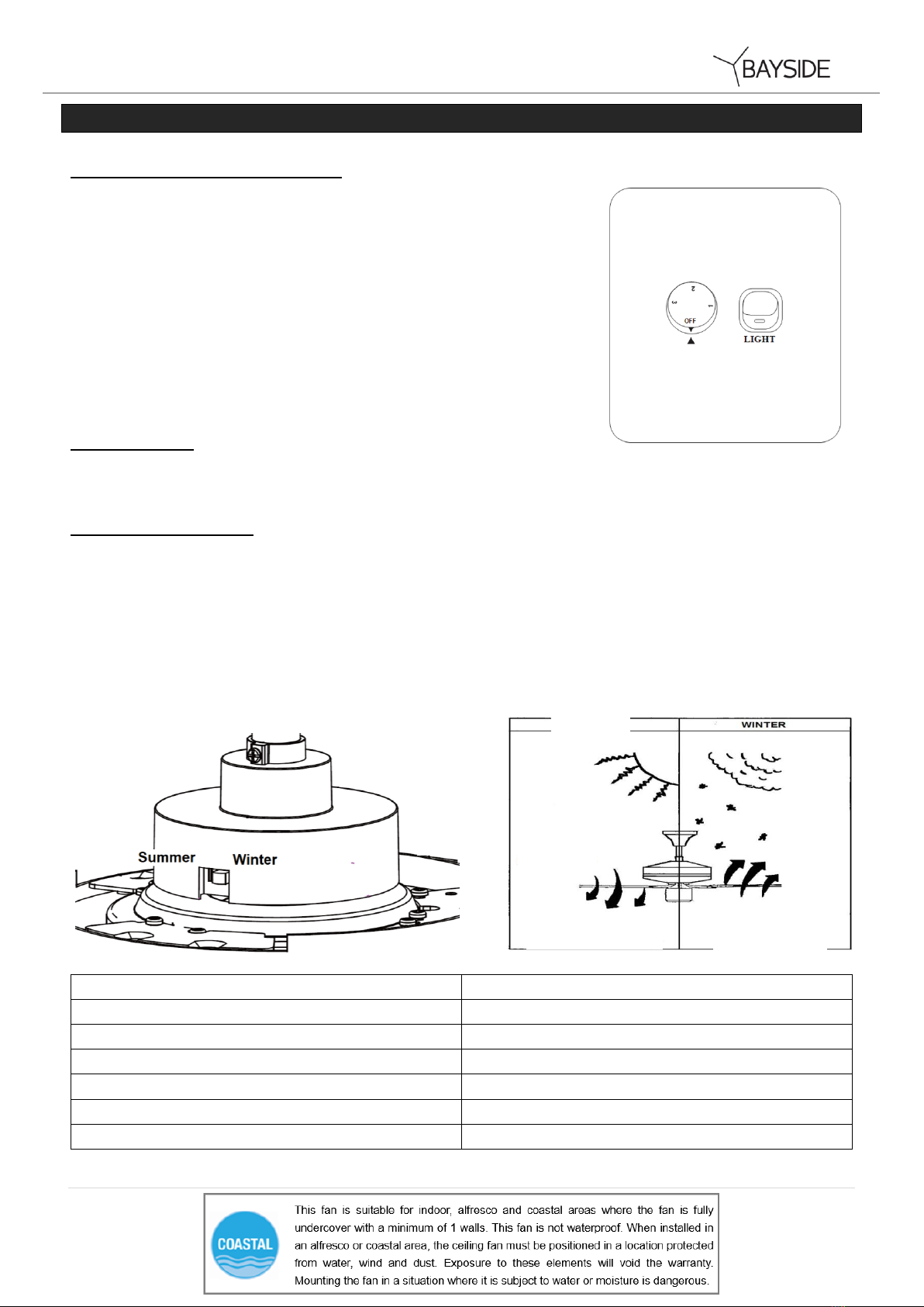
Turn on the power and check the operation of the fan.
• OFF Position – Fan off
• 3rd Position – Low fan speed
• 2nd Position – Medium fan speed
• 1st Position – High fan speed
Light Control
• Toggle Switch – On/off
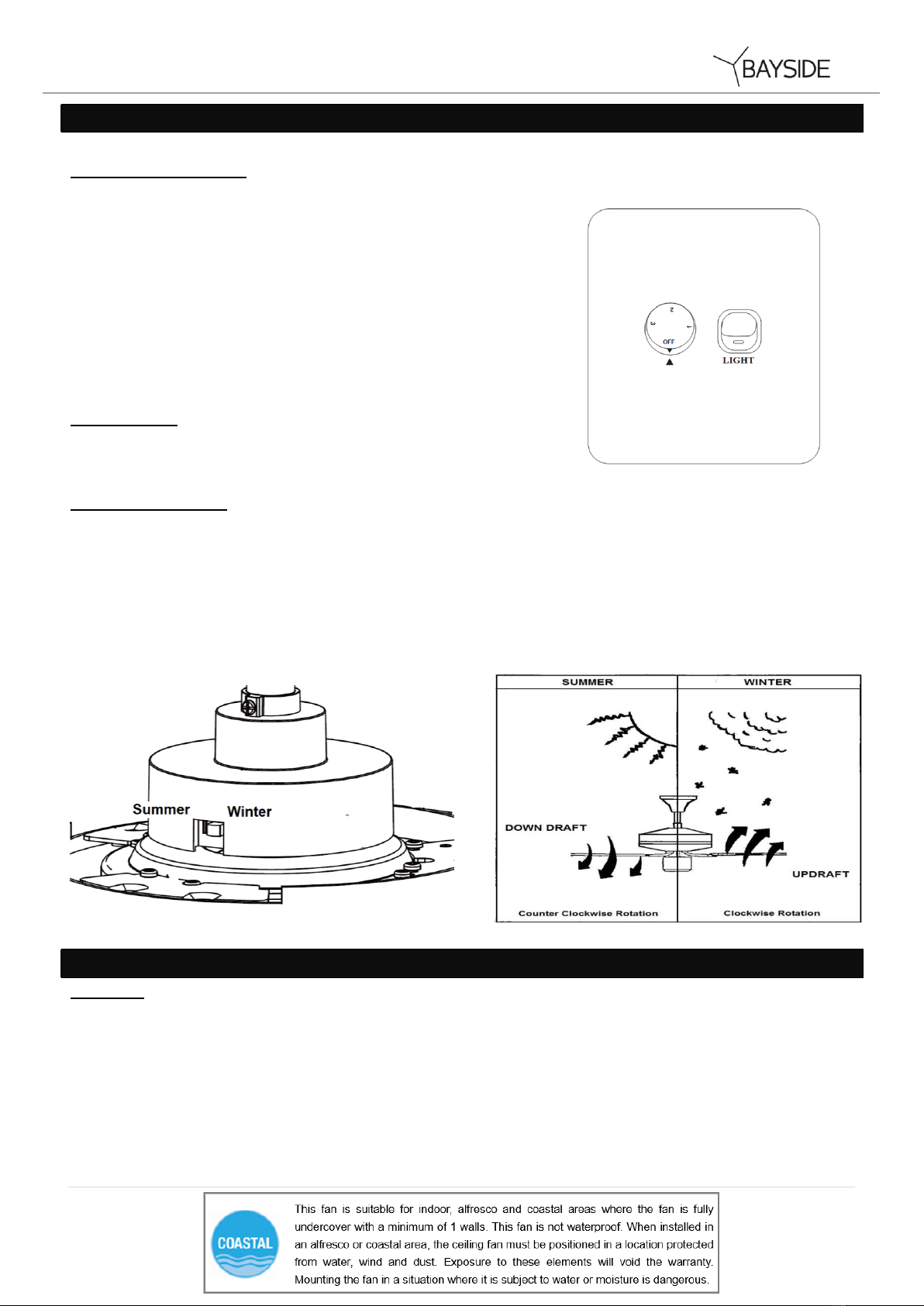
REVERSING SWITCH
Your ceiling fan can operate in either summer or winter mode.
SUMMER Mode: The reverse switch shall be in the “down” (SUMMER) position to make the fan rotate in an
anticlockwise direction. The airflow will be directed downwards, for cooling in summer.
WINTER Mode: The reverse switch shall be in the “up” (WINTER) position to make the fan rotate in a clockwise
direction. The airflow will be directed upwards assisting in the circulation of warm air, for energy conservation in
winter.
AFTER INSTALLATION
WOBBLE:
NOTE: ceiling fans tend to move during operation due to the fact that they are mounted on a rubber grommet. If the
fan was mounted rigidly to the ceiling it would cause excessive vibration. Movement of a few centimetres is quite
acceptable and DOES NOT suggest any problem.
TO REDUCE THE FAN WOBBLE: Please check that all screws which fix the mounting bracket and down rod are
secure.
Fig. 11
Fig. 10

Lagoon Fan Installation Instructions
10 | P a g e
BALANCING KIT: A balancing kit is provided to balance the ceiling fan on initial installation. Please refer to the
instruction on how to use the balancing kit. The balancing kit can be used to assist re-balancing should the ceiling
fan become un-balanced again. Store your balancing kit away after installation for future use if required.
NOISE:
When it is quiet (especially at night) you may hear occasional small noises. Slight power fluctuations and frequency
signals superimposed in the electricity for off-peak hot water control, may cause a change in fan motor noise. This
is normal. Please allow a 24-hour “settling-in” period, most noises associated with a new fan disappear during this
time.
The manufacturer’s warranty covers actual faults that may develop and NOT minor complaints such as hearing the
motor run –All electric motors are audible to some extent.
CARE AND CLEANING:
Periodic cleaning of your ceiling fan is the only maintenance required. Use a soft brush or lint free cloth to avoid
scratching the paint finish. Please turn off electricity power when you do so.
Do not immerse your ceiling fan in the water. It could damage the motor or the blades and create the possibility
of an electrical shock.
Ensure that the fitting does not come in contact with any organic solvents or cleaners.
To clean the fan blade, wipe with only a damp clean cloth with NO organic solvents or cleaners.
The motor has a permanently lubricated ball bearing so there is no need to oil.
NOTE: Always turn OFF the power at the mains switch before attempting to clean your fan.
TECHNICAL INFORMATION
Fan models
Rated Voltage
Rated power (motor)
Rated power lamp
52”blade fan only
220-240 VAC
55 W
N/A
52”blade fan with light
220-240 VAC
55 W
Max. 23 W, GX53
WARRANTY INFORMATION
IN AUSTRALIA / NEW ZEALAND –Please refer to the separated WARRANTY STATEMENT.
IN EUROPE –If you are a European customer please contact the retail outlet where the fan was
purchased for warranty service.

Lagoon Fan Installation Instructions
11 | P a g e
WIR GRATULIEREN ZUM KAUF DIESES PRODUKTES
Wir gratulieren zum Kauf dieses Qualitätsproduktes von Bayside. Bitte lesen Sie die Sicherheitshinweise vollständig
und sorgfältig durch, um den ordnungsgemäßen und sicheren Einsatz des Gerätes zu gewährleisten.
SICHERHEITSMASSREGELN
Die nachfolgenden Informationen auf dieser Seite dienen dazu einen störungsfreien und vor allem
sicheren Betrieb Ihres neuen Deckenventilators sicher zu stellen.
1. Europa: Dieses Gerät darf von Kindern im Alter von 8 Jahren und älter und von Personen mit
verminderten körperlichen, sensorischen oder geistigen Fähigkeiten, oder Personen, die keine
Erfahrung mit dem Einsatz des Gerätes haben, betrieben werden, vorausgesetzt diese werden dabei
überwacht, oder diese wurden ordnungsgemäßüber den sicheren Einsatz des Gerätes unterrichten
und verstehen die Gefahren, die mit dem Betrieb des Gerätes verbunden sind. Reinigungs- und
Wartungsarbeiten dürfen nicht von Kindern ohne die Aufsicht eines Erwachsenen ausgeführt werden.
2. Kinder müssen in der Umgebung dieses Geräts stets beaufsichtigt werden, um sicherzustellen dass
diese nicht mit dem Gerät spielen.
3. Ein allpoliger Trennschalter muss in der Kabelfestinstallation gemäß den örtlich geltenden
Vorschriften für elektrische Installationen integriert werden.
4. Entsorgen Sie elektrische Geräte niemals im regulären Hausmüll, sondern geben Sie das Gerät
stets ordnungsgemäßbei einer Sammelstelle für elektronische Altgeräte ab. Bitte treten Sie mit Ihrer
örtlichen Verwaltung in Kontakt für ausführliche Informationen bezüglich der Adressen der örtlichen
Sammelstellen. Wenn elektronische Geräte in Mülldeponien oder Landaufschüttungen entsorgt
werden, können gefährliche Substanzen in das Grundwasser und somit in den Lebensmittelkreislauf
geraten und die Gesundheit gefährden, oder gar Gesundheitsschäden verursachen.
5. Die tragende Struktur an der der Ventilator befestigt wird, muss mindestens ein Gewicht von 30kg
tragen können.
6. In Europa sollte der Ventilator so an der Decke befestigt werden, dass sich die Ventilatorflügel
mindestens 2,3m über dem Boden befinden, und in Australien sollten sich die Ventilatorflügel
mindestens ca. 2,1m über dem Boden befinden.
7. Dieser Ventilator ist nur für den Einsatz in geschlossenen Räumen geschaffen. Durch die Installation
an Orten wo der Ventilator Wasser oder Feuchtigkeit ausgesetzt würde, setzen Sie sich möglichen
Personenverletzungen oder anderen Gefahren aus, und die Garantie für das Gerät erlischt.
8. Die Installation des Gerätes sollte nur von einem qualifizierten und zugelassenen Elektriker
ausgeführt werden.

Lagoon Fan Installation Instructions
12 | P a g e
VOR DER INSTALLATION ZU BEACHTEN
Packen Sie Ihren Deckenventilator vorsichtig aus. Entfernen Sie alle Teile und Beschläge. Überprüfen
Sie alle Teile. Sie sollten Folgendes haben:
Ventilator ohne Lampe
Ventilator mit Lampe
1
Montagewinkel x 1
1
Montagewinkel x 1
2
Vormontierter Ventilatormotor,
Verbindungsstange und Baldachin x 1
2
Vormontierter Ventilatormotor,
Verbindungsstange und Baldachin x 1
3
Ventilatorflügel x 3
3
Ventilatorflügel x 3
4
Schraube für Montagewinkel x 2
4
GX53 x 1
5
Motorschrauben für Ventilatorflügel x 10
5
Schraube für Montagewinkel x 2
6
Auswuchtkit x 1 Satz
6
Motorschrauben für Ventilatorflügel x 10
7
Wandschalter x 1 Satz
7
Auswuchtkit x 1 Satz
8
Wandschalter x 1 Satz
Fig. 1
Lagoon Fan Installation Instructions
13 | P a g e
INSTALLATION DER DECKENHAL TERUNG
Der Deckenventilator muss an einem Ort installiert werden, wo die Flügelspitzen mindestens einen
Abstand von 30cm zum nächsten Gegenstand oder der Wand haben
Befestigen Sie die Halterung an einem sicheren Deckenträger oder einer strukturell äquivalenten
Stelle, die ein Gewicht von mindestens 30KG tragen kann, und verwenden Sie dazu die zwei
mitgelieferten Schrauben. Stellen Sie sicher, dass die Schraubengewinde mindestens 30mm in den
Untergrund eingedreht werden.
HINWEIS: Die für die Halterung mitgelieferten Schrauben sind nur für den Einsatz mit
Holzstrukturen geeignet. Für andere Materialien MÜSSEN entsprechend geeignete
Schraubentypen verwendet werden.
Installation an geneigten Decken
Dieses Ventilatorhalterungssystem ist nur für die Installation an
Decken mit einer Neigung von maximal 15 Grad geeignet.
Abb. 2
Abb. 3
Lagoon Fan Installation Instructions
14 | P a g e
AUFHÄNGUNG DES VENTILATORS
Setzen Sie die Ventilatoreinheit auf die Halterung auf. Stellen Sie sicher, dass die Führungsschlitze des
Kugelgelenks auf die Anschlagstifte der Halterung ausgerichtet sind, wodurch ein Verdrehen des
Ventiltors während des Betriebs verhindert wird. Abb.4)
INSTALLATION DER VENTILATORFLÜGEL
Befestigung der Ventilatorflügel
Fixieren Sie den Ventilatorflügel mithilfe von 3 Schrauben am Motor. Achten Sie darauf, beide Schrauben
gleichzeitig festzuziehen. (Überziehen Sie die Schrauben nicht, da dies die Ventilatorflügel beschädigen
könnte.)
Wenn Sie den Ventilatorflügel angebracht haben, wiederholen Sie den Vorgang mit den restlichen
Ventilatorflügeln.
Installation des Beleuchtungssets (für Ventilatoren mit Beleuchtung)
Installieren Sie die Glühlampe (max. 23W, GX53) in der
Lampenfassung.
Abb. 4
Abb. 5
Abb. 6

Lagoon Fan Installation Instructions
15 | P a g e
ELEKTRISCHES SCHALTDIAGRAMM
WARNHINWEIS: IM INTERESSE IHRER PERSÖNLICHEN SICHERHEIT MÜSSEN ALLE
ELEKTRISCHEN ANSCHLÜSSE VON EINEM ZUGELASSENEN ELEKTRIKER AUSGEFÜHRT
WERDEN.
HINWEIS: EIN ZUSÄTZLICHER, ALLPOLIGER TRENNSCHATER MUSS IN DER INSTALLATION DER
WANDVERKABELUNG ENTHALTEN SEIN.
DER EINSATZ MIT FEST INSTALLIERTEM WANDSCHALTER - SCHALTDIAGRAMM:
DER EINSATZ MIT FERNBEDIENUNG - SCHALTDIAGRAMM: (FERNBEDIENUNG ist getrennt
erhältlich)
1/ Fernbedienung ohne Stecker
Abb. 7
Abb. 8

Lagoon Fan Installation Instructions
16 | P a g e
2/ Fernbedienung mit Stecker
ABSCHLUSS DER INSTALLATION
Nach Abschluss der elektrischen Anschlüsse am Kabelblock der Halterung schließen Sie die
Verkabelung des den Deckenventilator über den Verbindungsstecker an der Netzstromversorgung
an.
Decken Sie die Halterung mit der Abdeckung ab. Die Verkabelung befindet sich nun unter der
Abdeckung und Sie sollten darauf achten, dass diese in diesem Schritt nicht beschädigt wird. Sichern
Sie die Abdeckung an der Halterung der Deckenstange mittels der mitgelieferten Schrauben.
Abb. 10
Abb. 9
Lagoon Fan Installation Instructions
17 | P a g e
DER BETRIEB DES DECKENVENTILATORS
VENTILATOR WANDSTEUERUNG
Schalten Sie die Stromversorgung ein, und überprüfen Sie die
Funktion des Ventilators.
• AUS-Stellung –Ventilator ist ausgeschaltet
• 3. Einstellposition – niedrige Ventilatorgeschwindigkeit
• 2. Einstellposition –mittlere Ventilatorgeschwindigkeit
• 1. Einrastposition – hohe Ventilatorgeschwindigkeit
Lichtsteuerung
• Kippschalter – Ein/Aus
RÜCKLAUFFUNKTION
Der Ventilator kann sowohl im Vorlauf als auch im Rücklauf betrieben werden.
SOMMERBETRIEB: Wenn der Schalter für die Rücklauffunktion auf “down” (SOMMER) steht, dreht der
Ventilator sich gegen den Uhrzeigersinn. Die Luftbewegung wird nach unten gelenkt und bringt im
Sommer den gewünschten Abkühlungseffekt.
WINTERBETRIEB: Wenn der Schalter für die Rücklauffunktion auf “up” (WINTER) steht, dreht sich der
Ventilator im Uhrzeigersinn. Die Luftbewegung wird nach oben gelenkt, um im Winter Energie zu sparen.
Reverse Switch
Umkehrschalter
Winter
Winter
Summer
Sommer
Down Draft
Abwind
Updraft
Aufwind
Counter clockwise Rotation
Linksdrehung
Clockwise Rotation
Rechtsdrehung
Abb. 12
Sommer
Abwind
Aufwind
Linksdrehung
Rechtsdrehung
Abb. 11

Lagoon Fan Installation Instructions
18 | P a g e
NACH DER INSTALLATION
SCHLINGERN:
HINWEIS: DECKENVENTILATOREN HABEN EINE NEIGUNG ZUM SCHLINGERN, DA SIE ÜBER DIE
AUFHÄNGUNG AN DER DECKE AUF EINER GUMMIVERBINDUNG GELAGERT SIND: WENN DER
VENTILATOR FEST AN DER DECKE ANGEBRACHT WÄRE, DANN WÜRDE DIE ROTATION
ÜBERMÄSSIGE VIBRATIONEN VERURSACHEN. ES IST NORMAL, DASS SICH DER VENTILATOR
EINIGE ZENTIMETER AUS DER MITTE BEWEGT, UND DIES STELLT UNTER NORMALEN
BETRIEBSBEDINGUNGEN KEINE STÖRUNG DAR.
REDUZIEREN DES SCHLINGERN: BITTE ÜBERPRÜFEN SIE, DASS ALLE SCHRAUBEN DER
DECKENHALTERUNG UND DIE VERBINDUNGSSCHRAUBEN DER HÄNGESTANGE FEST
ANGEZOGEN SIND.
HINWEIS: Dieser Ventilator wurde im Werk feinjustiert, und muss nicht wieder ausgewuchtet werden.
BETRIEBSGERÄUSCHE:
In einer sehr stillen Betriebsumgebung (besonders während der Nachtstunden) kann es vorkommen,
dass Sie gelegentlich leise Geräusche hören. Geringfügige Schwankungen in der Stromversorgung und
Frequenzsignale von anderen Geräten, z.B. Warmwassersteuerungen können dazu führen, dass
gelegentlich Motorgeräusche hörbar sind. Dies ist jedoch normal. Bitte beachten Sie, dass Sie den
Ventilator ca. 24 Stunden „einlaufen“ lassen müssen, und anschließend sollten Geräusche, die entstehen
weil der Ventilator neu ist, nicht mehr hörbar sein. Die Garantie des Herstellers erstreckt sich nur auf
tatsächliche Schäden oder Herstellungsfehler die während des nachfolgenden Betriebs auftreten, und
NICHT auf geringfügige Beschwerden, wie z.B. dass Motorlaufgeräusche hörbar sind. –Alle
Elektromotoren sind zu einem gewissen Grad während des Betriebs hörbar.
WARTUNG UND PFLEGE:
Die regelmäßige Reinigung des Ventilators ist die einzige Wartungsmaßnahme, die Ihr Ventilator
benötigt. Verwenden Sie eine weiche Bürste oder ein flusenfreies Tuch, um Kratzer auf den
Oberflächen des Gerätes zu vermeiden. Bitte schalten Sie stets die Stromversorgung zum Gerät
vollständig ab, bevor Sie mit der Reinigung beginnen.
Verwenden Sie zur Reinigung des Ventilators kein Wasser. Dadurch könnten der Motor oder die
Ventilatorflügel beschädigt werden, und Sie setzen sich zudem der Gefahr lebensbedrohlicher
Stromschläge aus.
Der Motor ist mit einem Kugellager mit Permanentschmierung ausgerüstet. Sie müssen das Lager
nicht schmieren.
HINWEIS: Schalten Sie die Stromversorgung zum Ventilator stets vollständig ab, bevor Sie mit der
Reinigung des Ventilators beginnen.
Lagoon Fan Installation Instructions
19 | P a g e
TECHNISCHE DATEN
GARANTIE-HINWEISE
KUNDEN IN AUSTRALIEN / NEU SEELAND –Bitte beachten Sie die separate
GARANTIEERKLÄRUNG.
KUNDEN IN EUROPA –Falls Sie ein Kunde in Europa sind, dann treten Sie für Garantieleistungen bitte
mit dem Fachgeschäft in Kontakt, wo Sie das Gerät gekauft haben.
VENTILATOR-Modelle
Nennspannung
Nennleistung (Motor)
Batterie für
Fernbedienung
Nur 132 cm Flügelventilator
220-240 V AC
55 W
Nicht zutreffend
132 cm Flügelventilator mit
Beleuchtung
220-240 V AC
55 W
Max. 22 W, GX53
Other manuals for LAGOON
2
Table of contents
Languages:
Other Bayside Fan manuals

Bayside
Bayside CALYPSO Installation guide

Bayside
Bayside NAUTILUS Owner's manual

Bayside
Bayside LAGOON User manual

Bayside
Bayside MEGARA User manual

Bayside
Bayside LAGOON CTC Installation guide

Bayside
Bayside NAUTILUS Installation guide

Bayside
Bayside LAGOON User manual

Bayside
Bayside CALYPSO Installation guide


