EyESonic DS-7200HFHI-ST series User manual

User Manual
www.eyesoniccctv.com

TABLE OF CONTENTS
DVR Pre-Installation.......................................................................................................................................2
DVR Installation ..............................................................................................................................................2
Hard Disk Installation.....................................................................................................................................2
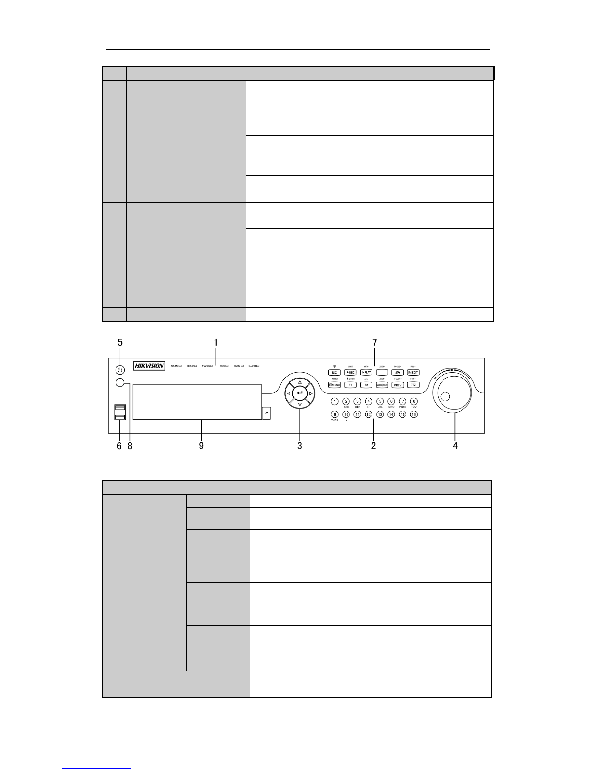
Front Panels......................................................................................................................................................5
Rear Panels.....................................................................................................................................................12
Peripheral Connections .................................................................................................................................15
Wiring of Alarm Input...........................................................................................................................15
Wiring of Alarm Output........................................................................................................................15
Alarm Connection....................................................................................................................................15
RS-485 and Controller Connection..........................................................................................................16
Termination Switch Operation.................................................................................................................17
Specifications..................................................................................................................................................18
Table 1 Specification for DS-7200HFHI-SL............................................................................................18
Table 2 Specification for DS-7200HFHI-SE............................................................................................19
Table 3 Specification for DS-7200HFHI-ST............................................................................................20
Table 4 Specification for DS-7300HFHI-SL............................................................................................21
Table 5 Specification for DS-7300HFHI-ST............................................................................................22
Table 6 Specification for DS-8100HFHI-SL............................................................................................23
Table 7 Specification for DS-8100HFHI-ST............................................................................................24
HDD Storage Calculation Chart...................................................................................................................27
Accessing by Web Browser............................................................................................................................28
Logging In................................................................................................................................................28
Live View.................................................................................................................................................28
Recording.................................................................................................................................................29
Playback...................................................................................................................................................30
Log .......................................................................................................................................................31
Menu Operation.............................................................................................................................................32
Menu Structure.........................................................................................................................................32
Startup and Shutdown..............................................................................................................................32
Live View.................................................................................................................................................33
Record Settings........................................................................................................................................33
Instant Recording.............................................................................................................................34
All-day Recording............................................................................................................................34
Playback...................................................................................................................................................35
Backup.....................................................................................................................................................36
1
www.eyesoniccctv.com

DVR Pre-Installation
The DS-7200HFHI-ST&SE&SL, DS-7300HFHI-ST&SL and DS-8100HFHI-ST&SL series DVR is highly
advanced surveillance equipment that should be installed carefully. Please take into consideration the following
precautionary steps before installation of the DVR.
1. Keep all liquids away from the DVR.
2. Install the DVR in a well-ventilated and dust-free area.
3. Ensure environmental conditions meet factory specifications.
4. Install a manufacturer recommended HDD.
DVR Installation
During the installation of the DVR:
1. Use brackets for rack mounting.
2. Ensure there is ample room for audio and video cables.
3. When installing cables, ensure that the bend radius of the cables are no less than five times than its diameter.
4. Connect both the alarm and RS-485 cable.
5. Allow at least 2cm (≈0.75-inch) of space between racks mounted devices.
6. Ensure the DVR is grounded.
7. Environmental temperature should be within the range of -10 ºC ~ 55 ºC , 14ºF ~ 131ºF.
8. Environmental humidity should be within the range of 10% ~ 90%.
Hard Disk Installation
Before you start:
Before installing a hard disk drive (HDD), please make sure the power is disconnected from the DVR. A factory
recommended HDD should be used for this installation.
Up to 8 SATA hard disks can be installed on your DVR.
Tools Required: Screwdriver.
2
www.eyesoniccctv.com

As the installation steps of HDD are similar among different models, here we take the steps of the
DS-7200HFHI-SE as an example.
Steps:
1. Remove the cover from the DVR by unfastening the screws on the back and side.
2. Connect one end of the data cable to the motherboard of DVR and the other end to the HDD.
3. Connect the power cable to the HDD.
4. Place the HDD on the bottom of the device and then fasten the screws on the bottom to fix the HDD.
3
www.eyesoniccctv.com

5. Re-install the cover of the DVR and fasten screws.
4
www.eyesoniccctv.com

Front Panels
Front Panel of DS-7204HFHI-SE & DS-7200HFHI-SL
Front Panel of DS-7208HFHI-SE
Description of Front Panel
No.
Name
Function Description
1
POWER
Power indicator turns yellow when the power switch on the real
panel is turned on.
STATUS
Status indicator blinks red when data is being read from or written to
HDD.
TX/RX
TX/RX indictor blinks yellow when network connection is
functioning properly.
2
IR Receiver
Receiver for IR remote
3
USB Interfaces
Universal Serial Bus (USB) ports for additional devices such as
USB mouse and USB Hard Disk Drive (HDD).
Front Panel of DS-7200HFHI-ST
Description of Control Panel Buttons
No.
Name
Function Description
1
POWER
Power indicator turns yellow once the power switch turns on.
READY
Ready indicator turns yellow when system is running.
STATUS
Status indicator turns red when SHIFT mode is on.
ALARM
Alarm indicator turns red when a sensor alarm is detected.
HDD
HDD indicator blinks red when data is being read from or written to
HDD.
TX/RX
TX/RX indictor blinks yellow when network connection is
functioning properly.
2
IR Receiver
Receiver for IR remote.
3
USB Interface
Universal Serial Bus (USB) ports for additional devices such as
USB mouse and USB Hard Disk Drive (HDD).
5
www.eyesoniccctv.com

No.
Name
Function Description
4
Composite
Keys
SHIFT
Switch between the numeric or letter input and functions of the
composite keys. (Input letter or numbers when the light is out;
Realize functions when the light is red.)
1/MENU
Enter numeral “1”;
Access the main menu interface.
2/ABC/F1
Enter numeral “2”;
Enter letters “ABC”;
The F1 button when used in a list field will select all items in the
list.
In PTZ Control mode, it will turn on/off PTZ light and when the
image is zoomed in, the key is used to zoom out.
3/DEF/F2
Enter numeral “3”;
Enter letters “DEF”;
The F2 button is used to change the tab pages.
In PTZ control mode, it zooms in the image.
4/GHI/ESC
Enter numeral “4”;
Enter letters “GHI”;
Exit and back to the previous menu.
5/JKL/EDIT
Enter numeral “5”;
Enter letters “JKL”;
Delete characters before cursor;
Check the checkbox and select the ON/OFF switch;
Start/stop record clipping in playback.
6/MNO/PLAY
Enter numeral “6”;
Enter letters “MNO”;
Playback, for direct access to all-day playback interface.
7/PQRS/REC
Enter numeral “7”;
Enter letters “PQRS”;
Open the manual record interface.
8/TUV/PTZ
Enter numeral “8”;
Enter letters “TUV”;
Access PTZ control interface.
9/WXYZ/PREV
Enter numeral “9”;
Enter letters “WXYZ”;
Multi-channel display in live view.
0/A
Enter numeral “0”;
Shift the input methods in the editing text field.(Upper and
lowercase, alphabet, symbols or numeric input).
5
DIRECTION
The DIRECTION buttons are used to navigate between different
fields and items in menus.
In the Playback mode, the Up and Down button is used to speed up
and slow down recorded video. The Left and Right button will select
the next and previous record files.
In Live View mode, these buttons can be used to cycle through
channels.
In PTZ control mode, it can control the movement of the PTZ
camera.
6
www.eyesoniccctv.com

No.
Name
Function Description
ENTER
The ENTER button is used to confirm selection in any of the menu
modes.
It can also be used to tick checkbox fields.
In Playback mode, it can be used to play or pause the video.
In single-frame Playback mode, pressing the button will advance the
video by a single frame.
In Auto-switch mode, it can be used to stop /start auto switch.
Front Panel of DS-7300HFHI-SL
Front Panel of DS-7300HFHI-ST
Description of Front Panel
No.
Name
Function Description
1
POWER
Power indicator lights in green when DVR is powered up.
READY
Ready indicator is normally green, indicating that the DVR is
functioning properly.
STATUS
Indicator turns green when DVR is controlled by an IR remote control
with the address from 1~254;
Indicator turns red when the SHIFT button is used;
Indicator does not light when the DVR is controlled by a keyboard or
by the IR remote control with the address of 255;
Indicator turns green when the DVR is controlled by IR remote control
(with the address from 1~254) and keyboard at the same time , and the
SHIFT button is not used;
Indicator turns orange : (a) when the DVR is controlled by IR remote
control (with the address from 1~254) and keyboard at the same time
and the SHIFT button is used as well; (b) when the DVR is controlled
by IR remote control (with the address from 1~254) and the SHIFT
button is used.
ALARM
Alarm indicator turns red when a sensor alarm is detected.
HDD
HDD indicator blinks in red when data is being read from or written to
HDD.
TX/RX
TX/RX indictor blinks in green when network connection is
functioning properly.
2
DVD-R/W
Slot for DVD-R/W.
7
www.eyesoniccctv.com

No.
Name
Function Description
3
Composite
Keys
SHIFT
Switch between the numeric or letter input and functions of the
composite keys. (Input letter or numbers when the light is out; Realize
functions when the light is red.)
1/MENU
Enter numeral “1”;
Access the main menu interface.
2/ABC/F1
Enter numeral “2”;
Enter letters “ABC”;
The F1 button when used in a list field will select all items in the list.
In PTZ Control mode, it will turn on/off PTZ light and when the image
is zoomed in, the key is used to zoom out.
In live view or playback mode, the F1 button can be used to switch
between main and spot video output.
3/DEF/F2
Enter numeral “3”;
Enter letters “DEF”;
The F2 button is used to change the tab pages.
In PTZ control mode, it zooms in the image.
4/GHI/ESC
Enter numeral “4”;
Enter letters “GHI”;
Exit and back to the previous menu.
5/JKL/EDIT
Enter numeral “5”;
Enter letters “JKL”;
Delete characters before cursor;
Check the checkbox and select the ON/OFF switch;
Start/stop record clipping in playback.
6/MNO/PLAY
Enter numeral “6”;
Enter letters “MNO”;
In Playback mode, it is used for direct access to playback interface.
7/PQRS/REC
Enter numeral “7”;
Enter letters “PQRS”;
Manual record, for direct access to manual record interface; manually
enable/disable record.
8/TUV/PTZ
Enter numeral “8”;
Enter letters “TUV”;
Access PTZ control interface.
9/WXYZ/PREV
Enter numeral “9”;
Enter letters “WXYZ”;
Multi-channel display in live view.
0/A
Enter numeral “0”;
Shift the input methods in the editing text field. (Upper and lowercase,
alphabet, symbols or numeric input).
4
DIRECTION
The DIRECTION buttons are used to navigate between different fields
and items in menus.
In the Playback mode, the Up and Down button is used to speed up and
slow down recorded video. The Left and Right button will select the
next and previous record files.
In Live View mode, these buttons can be used to cycle through
channels.
8
www.eyesoniccctv.com

No.
Name
Function Description
In PTZ control mode, it can control the movement of the PTZ camera.
ENTER
The ENTER button is used to confirm selection in any of the menu
modes.
It can also be used to tick checkbox fields.
In Playback mode, it can be used to play or pause the video.
In single-frame Playback mode, pressing the button will advance the
video by a single frame.
In Auto-switch mode, it can be used to stop /start auto switch.
5
POWER
Power on/off switch.
6
JOG SHUTTLE Control
Move the active selection in a menu. It will move the selection up and
down.
In Live View mode, it can be used to cycle through different channels.
In the Playback mode, it can be used to jump 30s forward/backward in
video files.
In PTZ control mode, it can control the movement of the PTZ camera.
7
USB Interface
Universal Serial Bus (USB) ports for additional devices such as USB
mouse and USB Hard Disk Drive (HDD).
8
IR Receiver
Receiver for IR remote control.
Front Panel of DS-8100HFHI-ST & SL
Description of Front Panel
No.
Name
Function Description
1
Status
Indicators
ALARM
Alarm indicator turns red when a sensor alarm is detected.
READY
Ready indicator is normally blue, indicating that the DVR is
functioning properly.
STATUS
Indicator turns blue when DVR is controlled by an IR remote.
Indicator turns red when controlled by a keyboard and orange when
IR remote and keyboard is used at the same time.
Indicator does not light when the DVR is controlled by the IR remote
control with the address of 255.
HDD
HDD indicator blinks in red when data is being read from or written
to HDD.
TX/RX
TX/RX indictor blinks in blue when network connection is
functioning properly.
GUARD
Indicator turns blue when the device is armed;
Indicator does not light when the device is disarmed;
The arm/disarm state can be initiated by pressing and holding on the
ESC button for more than 3 seconds in live view mode.
2
Alphanumeric Buttons
Switch to the corresponding channel in Live view or PTZ Control
mode.
9
www.eyesoniccctv.com

No.
Name
Function Description
Input numbers and characters in Edit mode.
Switch between different channels in Playback mode.
The light of the button is blue when the corresponding channel is
recording; it is red when the channel is in network transmission
status; it is pink when the channel is recording and transmitting.
3
Control
Buttons
DIRECTION
The DIRECTION buttons are used to navigate between different
fields and items in menus.
In the Playback mode, the Up and Down button is used to speed up
and slow down recorded video. The Left and Right button will select
the next and previous record files.
In Live View mode, these buttons can be used to cycle through
channels.
In PTZ control mode, it can control the movement of the PTZ
camera.
ENTER
The ENTER button is used to confirm selection in any of the menu
modes.
It can also be used to tick checkbox fields.
In Playback mode, it can be used to play or pause the video.
In single-frame Playback mode, pressing the button will advance the
video by a single frame.
In Auto-switch mode, it can be used to stop /start auto switch.
4
JOG SHUTTLE Control
Move the active selection in a menu. It will move the selection up
and down.
In Live View mode, it can be used to cycle through different
channels.
In the Playback mode: the outer ring is used to speed up or slow
down the record files and the inner ring is used to jump 30s
forward/backward in records files.
In PTZ control mode, it can control the movement of the PTZ
camera.
5
POWER
Power on/off switch.
6
USB Interfaces
Universal Serial Bus (USB) ports for additional devices such as USB
mouse and USB Hard Disk Drive (HDD).
7
Composite
Keys
ESC
Exit and back to the previous menu.
Arm/disarm the DVR in live view mode.
REC/SHOT
Enter the Manual Record setting menu.
In PTZ control settings, press the button and then you can call a PTZ
preset by pressing Numeric button.
It is also used to turn audio on/off in the Playback mode.
PLAY/AUTO
Enter the Playback menu;
Auto scan in the PTZ Control mode.
ZOOM+
Zoom in the PTZ camera in the PTZ Control setting.
A/FOCUS+
Adjust focus in the PTZ Control menu.
It is also used to switch between input methods (upper and lowercase
alphabet, symbols and numeric input).
10
www.eyesoniccctv.com

No.
Name
Function Description
EDIT/IRIS+
Edit text fields. When editing text fields, it will also function as a
Backspace button to delete the character in front of the cursor.
On checkbox fields, pressing the button will tick the checkbox.
In PTZ Control mode, the button adjusts the iris of the camera.
In Playback mode, it can be used to generate video clips for backup.
Enter/exit the folder of USB device and eSATA HDD.
MAIN/SPOT/Z
OOM-
Switch between main and spot output.
In PTZ Control mode, it can be used to zoom out the image.
F1/ LIGHT
Select all items on the list when used in a list field.
In PTZ Control mode, it will turn on/off PTZ light (if applicable).
In Playback mode, it is used to switch between play and reverse play.
F2/ AUX
Cycle through tab pages.
In synchronous playback mode, it is used to switch between channels.
MENU/WIPER
Press the button will help you return to the Main menu (after
successful login).
Press and hold the button for 5 seconds will turn off audible key
beep.
In PTZ Control mode, the MENU/WIPER button will start wiper (if
applicable).
In Playback mode, it is used to show/hide the control interface.
PREV/FOCUS-
Switch between single screen and multi-screen mode.
In PTZ Control mode, it is used to adjust the focus in conjunction
with the A/FOCUS+ button.
PTZ/IRIS-
Enter the PTZ Control mode.
In the PTZ Control mode, it is used to adjust the iris of the PTZ
camera.
8
IR Receiver
Receiver for IR remote control.
9
DVD-R/W
Slot for DVD-R/W.
11
www.eyesoniccctv.com

Rear Panels
DS-7204HFHI-SL
DS-7208HFHI-SL
DS-7204HFHI-SE
DS-7204HFHI-ST
DS-7208HFHI-SE and DS-7208HFHI-ST
No.
Item
Description
1
VIDEO IN
HD-SDI interface for video input.
2
AUDIO IN
RCA connector
3
AUDIO OUT
RCA connector
4
VGA
DB15 connector for VGA output. Display local video output and menu.
5
HDMI
HDMI video output connector.
6
USB Port
Universal Serial Bus (USB) port for additional devices.
7
Network Interface
Connector for network
8
RS-485 Interface
Connector for RS-485 devices.
9
Power Supply
DC 12V power supply.
10
Power Switch
Switch for turning on/off the device.
11
GND
Ground
12
www.eyesoniccctv.com

DS-7300HFHI-SL
DS-7300HFHI-ST
DS-8100HFHI-SL
DS-8100HFHI-ST
No.
Item
Description
1
VIDEO IN
HD-SDI interface for video input.
2
VIDEO OUT
BNC connector for video output.
3
AUDIO IN
RCA connector
4
USB Port
Universal Serial Bus (USB) port for additional devices.
5
HDMI
HDMI video output connector.
6
VGA
DB15 connector for VGA output. Display local video output and
menu.
7
AUDIO OUT
RCA connector
8
Network Interface
Connector for network
9
RS-485 Interface
Connector for RS-485 devices. T+ and T- pins connect to R+ and R-
13
www.eyesoniccctv.com

No.
Item
Description
pins of PTZ receiver respectively.
D+, D- pin connects to Ta, Tb pin of controller. For cascading
devices, the first DVR’s D+, D- pin should be connected with the
D+, D- pin of the next DVR.
Connector for alarm input.
Connector for alarm output.
10
Power Supply
AC 100 ~ 240V power supply.
11
Power Switch
Switch for turning on/off the device.
12
GND
Ground
13
LINE IN
BNC connector for audio input.
14
eSATA
Connects external SATA HDD, CD/DVD-RW.
15
RS-232 Interface
Connector for RS-232 devices.
16
Termination Switch
(for DS-7300HFHI-ST and
DS-8100HFHI-ST)
RS-485 termination switch.
Up position is not terminated.
Down position is terminated with 120Ωresistance.
14
www.eyesoniccctv.com

Peripheral Connections
Wiring of Alarm Input
The alarm input is an open/closed relay. To connect the alarm input to the device, use the following diagram.
If the alarm input is not an open/close relay, please connect an external relay between the alarm input and the
device.
Wiring of Alarm Output
To connect to an alarm output (AC or DC load), use the following diagram:
DC Load Connection Diagram AC Load Connection Diagram
For DC load, the jumpers can be used within the limit of 12V/1A safely.
To connect an AC load, jumpers should be left open (you must remove the jumper on the motherboard in the
DVR). Use an external relay for safety (as shown in the figure above).
There are 4 jumpers (JP1, JP2, JP3, and JP4) on the motherboard, each corresponding with one alarm output. By
default, jumpers are connected. To connect an AC load, jumpers should be removed.
Example:
If you connect an AC load to the alarm output 3 of the DVR, then you must remove the JP 3.
Alarm Connection
To connect alarm devices to the DVR:
1. Disconnect pluggable block from the ALARM IN /ALARM OUT terminal block.
2. Press and hold the orange part of the pluggable block; insert signal cables into slots and release the orange part.
Ensure signal cables are in tight.
15
www.eyesoniccctv.com

3. Connect pluggable block back into terminal block.
RS-485 and Controller Connection
For DS-7200HFHI-SL, DS-7200HFHI-SE & DS-7200HFHI-ST
To connect PTZ to the DVR:
1. Disconnect pluggable block from the RS-485 terminal block.
2. Press and hold the orange part of the pluggable block; insert signal cables into slots and release the orange
part. Ensure signal cables are in tight.
3. Connect A+ on PTZ to D+ on terminal block and B- on controller to D- on terminal block. Fasten stop
screws.
4. Connect pluggable block back into terminal block.
For DS-7300HFHI-ST&SL & DS-8100HFHI-ST&SL
To connect PTZ to the DVR:
1. Disconnect pluggable block from the RS-485 terminal block.
2. Press and hold the orange part of the pluggable block; insert signal cables into slots and release the orange
part. Ensure signal cables are in tight.
3. Connect A+ on PTZ to T+ on terminal block and B- on controller to T- on terminal block. Fasten stop
screws.
4. Connect pluggable block back into terminal block.
To connect a controller to the DVR:
1. Disconnect pluggable block from the KB terminal block.
16
www.eyesoniccctv.com

2. Press and hold the orange part of the pluggable block; insert signal cables into slots and release the orange
part. Ensure signal cables are in tight.
3. Connect Ta on controller to D+ on terminal block and Tb on controller to D- on terminal block. Fasten stop
screws.
4. Connect pluggable block back into terminal block.
Make sure both the controller and DVR are grounded. Here we take the controller connection of the
DS-8100HFHI-ST as an example.
Termination Switch Operation
This function is applicable to the DS-7300HFHI-ST&SL and DS-8100HFHI-ST&SL.
Purpose:
To connect the DVR with several speed domes, the bus topology can be adopted, which means the speed domes
are connected with each other via the R+ and R- of RS-485 serial interface. But due to the impedance of 485 wire,
the longer the wire is, the greater the impedance gets.
To avoid the signal reduction caused by the great impedance of long distance transmission, please connect two
120Ω resistors in the circuit: one resistor between the DVR and the nearest speed dome, and the other one after the
furthest speed dome.
Steps:
1. Turn on the SW switches on the DVR and the furthest speed dome.
2. Keep other SW switches off.
The connection diagram and status of each SW switch are shown in the following figure.
For the DS-7300HFHI-SL and DS-8100HFHI-SL series DVR, the termination switch is placed on the
mainboard instead of the rear panel. Open the upper cover and turn on/off the SW switch if needed.
17
www.eyesoniccctv.com

Specifications
Table 1 Specification for DS-7200HFHI-SL
Model
DS-7204HFHI-SL
DS-7208HFHI-SL
Video/Audio
input
Video compression
H.264
HD-SDI video input
4-ch
8-ch
HD-SDI interface (800 mVp-p, 75 Ω)
Supported HD-SDI
camera types
1080I60, 1080I50, 1080P30, 1080P25, 720P60, 720P50, 720P30,
720P25
Audio compression
G.711u
Audio in /
Two-way audio in
1-ch, RCA (2.0 Vp-p, 1 KΩ)
Video/Audio
output
HDMI / VGA output
1920 ×1080 / 60 Hz, 1280 ×1024 / 60 Hz, 1280 ×720 / 60 Hz,
1024 ×768 / 60 Hz
Encoding resolution
Main stream: 1080P@12fps / 720P / VGA / WD1 / 4CIF / CIF
Sub-stream: WD1(non-real-time) / 4CIF(non-real-time) / CIF /
QCIF / QVGA
Frame rate
Main stream: 1/16 fps ~ Real time frame rate
Sub-stream: 1/16 fps ~ Real time frame rate
Video bitrate
32 Kbps-6 Mbps
Audio output
1-ch, RCA (Linear, 1KΩ)
Audio bitrate
64 Kbps
Dual-stream
Support
Stream type
Video, Video & Audio
Synchronous playback
4-ch
Playback resolution
1080P / 720P / WD1 / 4CIF / VGA / CIF / QVGA / QCIF
Network
management
Remote connection
128
Network protocols
TCP/IP, PPPoE, DHCP, DNS, DDNS, NTP, SADP, SMTP, SNMP,
NFS, iSCSI, UPnP™
Hard disk
SATA
1 SATA interface
Capacity
Up to 4 TB capacity for each disk
External
interface
Network interface
1; 10M/100Mbps self-adaptive
Ethernet interface
1; 10M/100M/1000Mbps
self-adaptive Ethernet interface
Serial interface
1; standard RS-485 serial interface, half-duplex
USB port
2 ×USB2.0
General
Power supply
12V DC
Consumption
(without hard disk)
Max. 15W
Max. 20W
Working temperature
-10 ºC ~+55 ºC (14 ºF ~ 131 ºF)
Working humidity
10% ~ 90%
Chassis
Stand-alone 1U chassis
Dimensions
315×242×45 mm (12.3×9.5×1.8 inch)
18
www.eyesoniccctv.com

Table 2 Specification for DS-7200HFHI-SE
(W ×D ×H)
Weight
(without hard disks)
1 kg / 2.2lb
Model
DS-7204HFHI-SE
DS-7208HFHI-SE
Video/Audio
input
Video compression
H.264
HD-SDI video input
4-ch
8-ch
HD-SDI interface (800 mVp-p, 75 Ω)
Supported HD-SDI
camera types
1080I60, 1080I50, 1080P30, 1080P25, 720P60, 720P50, 720P30,
720P25
Audio compression
G.711u
Audio input
4-ch
8-ch
RCA (2.0 Vp-p, 1 KΩ)
Two-way audio input
1-ch, RCA (2.0 Vp-p, 1 KΩ), (using the 1st channel of audio input)
Video/Audio
output
HDMI / VGA output
1920 ×1080 / 60 Hz,1280 ×1024 / 60 Hz, 1280 ×720 / 60 Hz,
1024 ×768 / 60 Hz
Encoding resolution
Main stream: 1080P@12fps / 720P / VGA / WD1 / 4CIF / CIF
Sub-stream: WD1(non-real-time) / 4CIF(non-real-time) / CIF /
QCIF / QVGA
Frame rate
Main stream: 1/16 fps ~ Real time frame rate
Sub-stream: 1/16 fps ~ Real time frame rate
Video bitrate
32 Kbps-6 Mbps
Audio output
1-ch, RCA (Linear, 1KΩ)
Audio bitrate
64 Kbps
Dual-stream
Support
Stream type
Video, Video & Audio
Synchronous playback
4-ch
(up to 2-ch 720P real time)
8-ch
(up to 2-ch 720P real time)
Playback resolution
1080P / 720P / VGA / WD1 / 4CIF / CIF / QVGA / QCIF
Network
management
Remote connection
128
Network protocols
TCP/IP, PPPoE, DHCP, DNS, DDNS, NTP, SADP, SMTP, SNMP,
NFS, iSCSI, UPnP™
Hard disk
SATA
1 SATA interface
2 SATA interfaces
Capacity
Up to 4 TB capacity for each disk
External
interfaces
Network interface
1; 10M / 100M / 1000M self-adaptive Ethernet interface
Serial interface
1; standard RS-485 serial interface, half-duplex
USB port
2 ×USB2.0
Alarm in / out
(optional)
4 / 1
General
Power supply
12V DC
Consumption (without
Max. 15 W
Max. 20 W
19
www.eyesoniccctv.com
This manual suits for next models
5
Table of contents