E. Install Rear Panel (Fig. E.)
E.1 Position the rear panel as shown, aligning holes in rear panel
with holes in the rear mounts on the side frame.
E.2 At each side of the vehicle, install a 5/16” x 3/4” carriage bolt,
with a plastic washer, flat washer, and locknut through each of
the two lower holes in the rear panel, rear mount, and side
frame as shown.
E.3 Install a 5/16” x 3/4” carriage bolt, flat washer, and locknut
through the horizontal flange of the rear panel and side frame.
(NOTE: the top row of fasteners will be installed during rear
window installation.)
E.4 Align the edges of the rear panel with the outside edges of
side frame. Tighten all hardware.
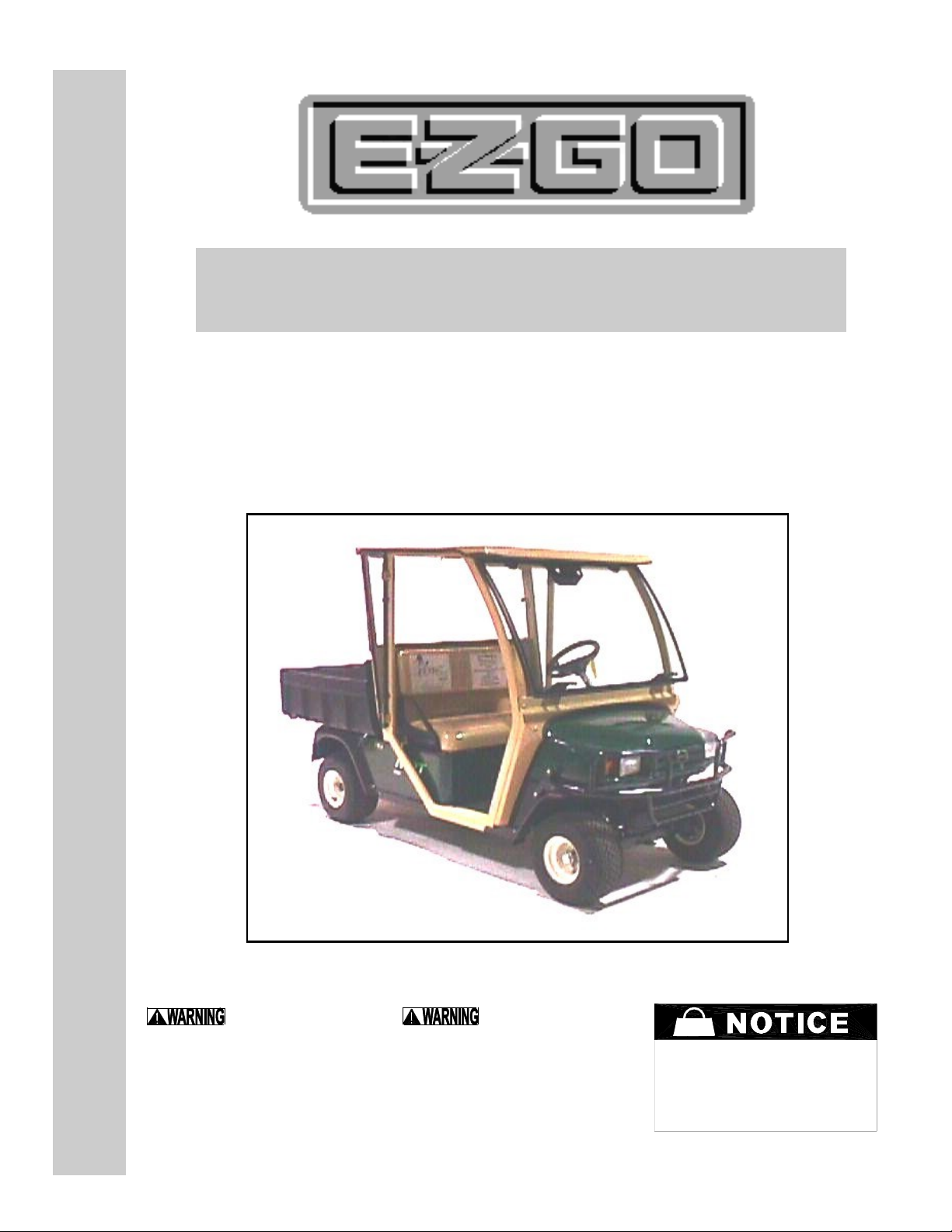
E.5 Bolt bottom of rear panel to seat back support plate with 5/16”
x 1” button head bolt, flat washer, and locknut. (CAUTION: do
not trap rubber access cover, MPT/IND 800E/1000)
E.6 Re-install access door for oil dip stick to the back, vertical sur-
face of the rear panel using the two rivets provided. Install
rivets from inside of cab. (gas models MPT/IND 1200 only)
E.7 Re-install the metal seat back supports that were removed in
step A.3. Use the original equipment hardware.
E.8 Re-install seatback to holes in rear panel and metal seat back
supports using the original equipment bolts and washers re-
moved in step A.2.
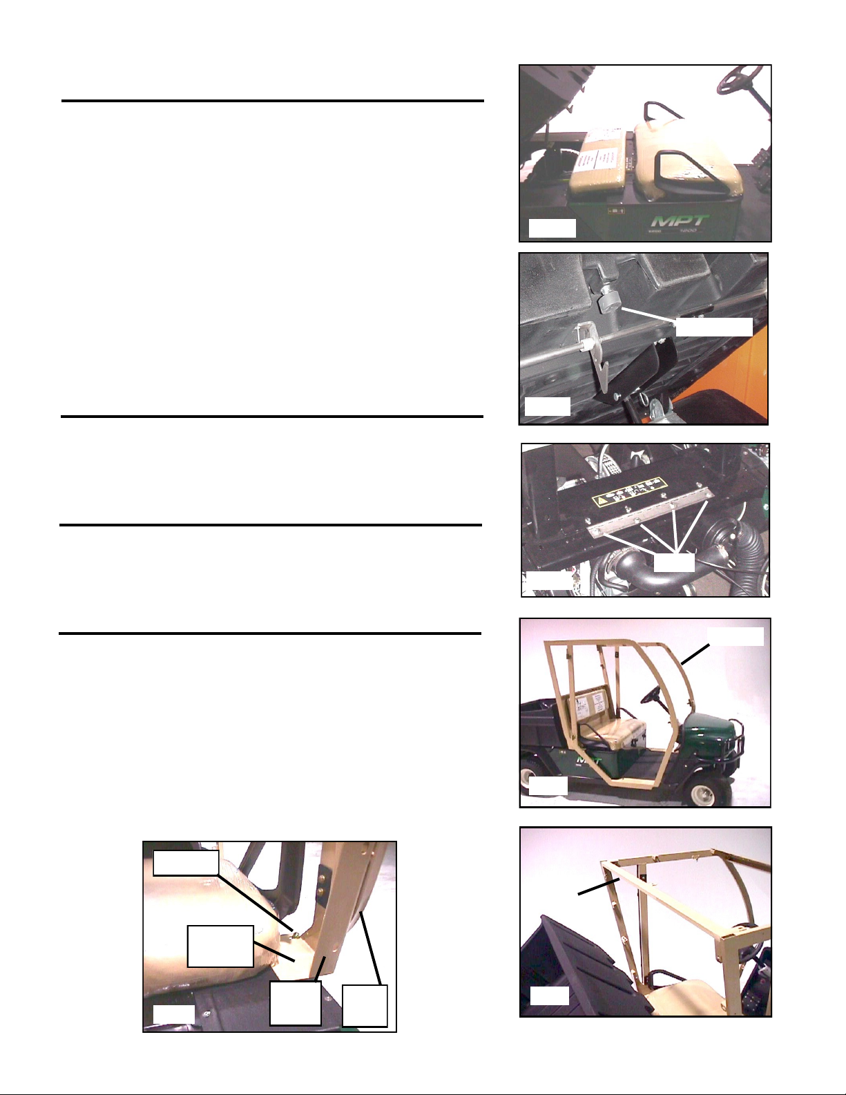
F. Assemble the Front Cowl (Fig. F.)
F.1 Secure the right and left front fillers to the front cowl using
5/16” x 3/4” carriage bolts, plastic washers, flat washers, and
nylon locknuts.
F.2 Install 1” bulb rubber onto the inside edge of front cowl
assembly. The 1” bulb rubber should begin and end on the
bottom inside edge of front fillers as shown (Fig. F.2.). Trim
any extra 1” bulb rubber.
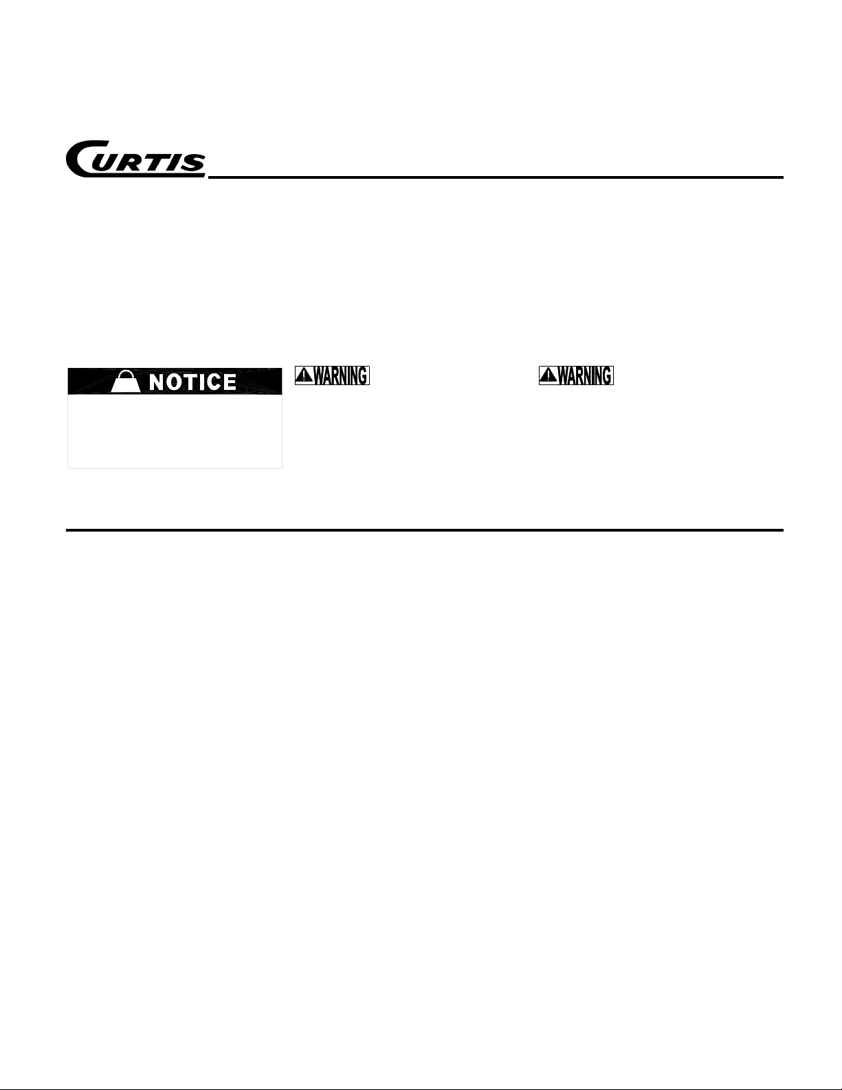
G. Install Front Cowl (Fig. G.)
G.1 Position front cowl assembly by aligning holes in front cowl
with the holes in the mounting tabs on the side frames. Install
using 5/16” x 3/4” carriage bolts, flat washers, and nylon
locknuts through the horizontal flange of the front cowl and
side frame.
G.2 Align the edges of the front cowl assembly with the outside
edges of the side frames and fasten in place using 5/16” x 3/4”
carriage bolts, flat washers, and nylon locknuts.
H. Install Windshield Support (Fig. H)
H.1 Align the holes in the windshield support with the holes in the
mounting tabs on the side frames and install 5/16” x 3/4”
carriage bolts, plastic washers, flat washers, and nylon
locknuts as shown. (Fig. H.1) See following note.
NOTE
• Hardware will be installed in the top holes of the windshield
support during roof installation.
• The purpose of the plastic washers installed underneath
the carriage bolt heads directly against the cab exterior is
to provide a weather seal. Do not over tighten this hardware,
which could damage the plastic washers.
page 4 of 11
1” Bulb
Rubber
Front Fillers
Windshield Cowl
Fig. F.
Fig. G.
F.2.
Fig. H.
Fig. E.
rear panel
cowl