F5 ARX 6000 Parts list manual

ARX 6000 FRU Replacement Guide
Platform P100
April 4, 2011. Version 1.0

- 1 –
Copyright © 2010, F5 Networks, Inc. All rights reserved.
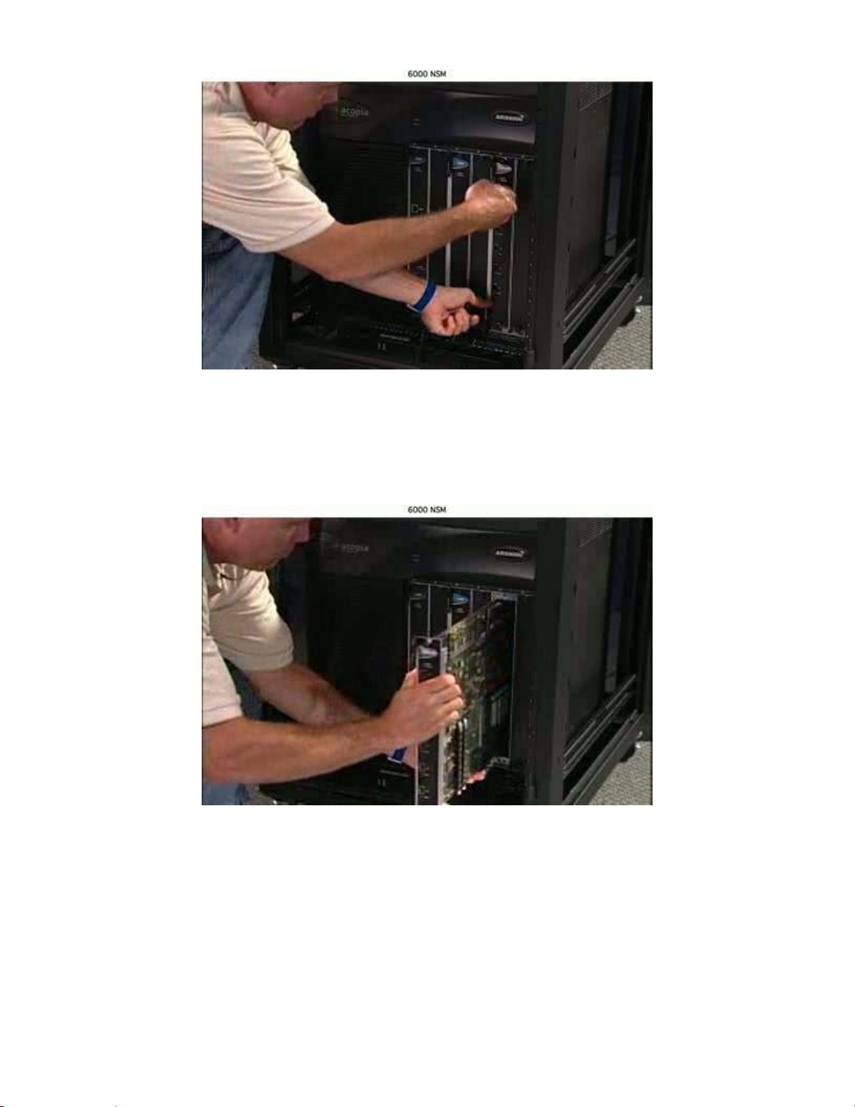
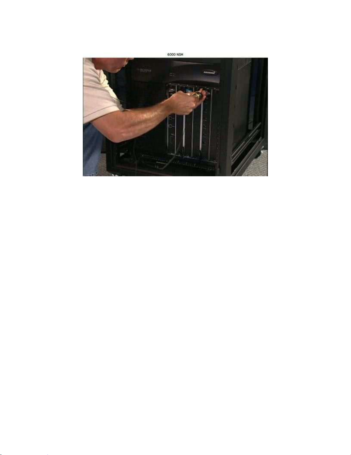
Removing and Replacing Cards and Components
Removing a card causes a switch to reboot
In a redundant pair where this switch is active, services fail over to the junior switch. In
a redundant pair where this switch is in the Backup/junior role, service is unaffected. A
standalone switch does not offer any service for the duration of the reboot.
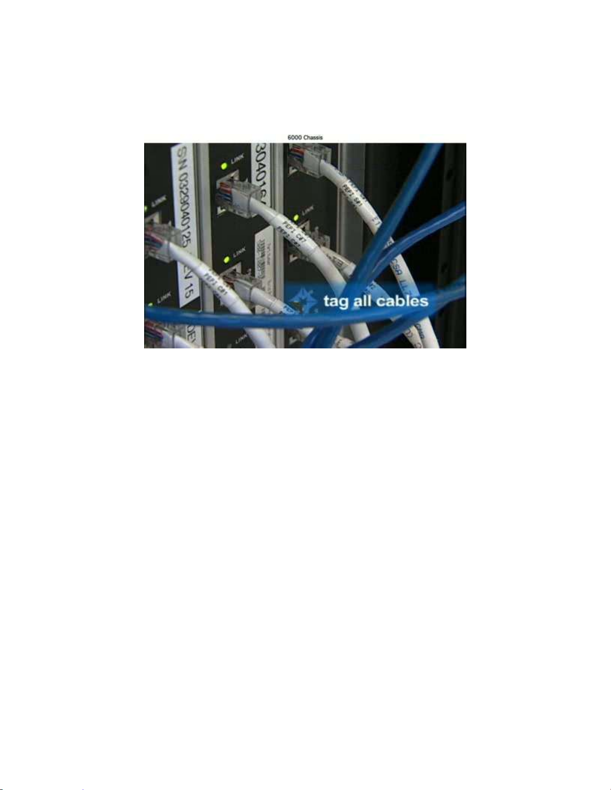
Static electricity can damage switch components. Be sure to wear anti-
static wrist straps before handling disk drives and cards.
CAUTION
WARNING

- 2 –
Copyright © 2010, F5 Networks, Inc. All rights reserved.
ARX 6000 Chassis Overview –Front without bezel
The ARX 6000 is highly modularized in its design and it intended to be
serviced in the field primarily through the replacement of Field
Replaceable Units (FRU’s). The remainder of this document provide
instruction on how to replace each FRU used in the ARX 6000.

- 3 –
Copyright © 2010, F5 Networks, Inc. All rights reserved.
ARX 6000 Chassis Overview –Rear

- 4 –
Copyright © 2010, F5 Networks, Inc. All rights reserved.
Preparation
Before replacing any FRU in an ARX 6000, ensure that the Field Tech completes the following steps.
Step 1 - Install Grounding Strap
Before replacing any FRU on the ARX 6000, ensure that the Field Tech uses a grounding
strap as shown below to protect modules and components from potential static electricity
discharge. Fig. 1
Fig. 2

- 5 –
Copyright © 2010, F5 Networks, Inc. All rights reserved.
Step 2 –Tag all Cables
Instruct the Field Tech to apply labels to all cables that connect to the ARX 6000

- 6 –
Copyright © 2010, F5 Networks, Inc. All rights reserved.
Replacement of NSM Card
Preparation
Step 2 Tag all cables Fig. 3
Step 1 Remove the NSM card
Verify that the Field Tech is using a Ground Strap and that the Tech has tagged all cables.
Instruct the Field Tech loosen the top and bottom captive screws on the NSM card.
Fig. 4
Have the Fiel Tech grasp both of the ejector handles located to the left of the screws and pull
evenly to slide the card out.

- 7 –
Copyright © 2010, F5 Networks, Inc. All rights reserved.
Fig. 5
Instruct the Field Tech to keep hold of the handles andslowly pull the card straight out of the
slot until it is clear of the unit. Fig. 6

- 8 –
Copyright © 2010, F5 Networks, Inc. All rights reserved.
Step 4 Replacing the NSM card
To replace the NSM card, line up the replacement card to the guide slots and slide completely
into the ARX 6000. Fig. 7
Push in both the top and bottom handles to re-seat the NSM card.
Fig. 8

- 9 –
Copyright © 2010, F5 Networks, Inc. All rights reserved.
Re-tighten the top and bottom captive screws and remove the grounding strap.
Fig. 9
Step 5 Follow-up
Have the Field Tech standby while you ensure that the new part is functional

- 10 –
Copyright © 2010, F5 Networks, Inc. All rights reserved.
Replacement of SCM Card
Preparation
Step 3 Remove the SCM card
To remove the SCM card, loosen the top and bottom captive screws on the SCM card.
Fig. 13

- 11 –
Copyright © 2010, F5 Networks, Inc. All rights reserved.
Grasp both of the ejector handles located to the left of the screws and pull evenly to slide the
card out. Fig. 14
Keeping hold of the handles, slowly pull the card straight out of the slot until it is clear of the
unit. Fig. 15

- 12 –
Copyright © 2010, F5 Networks, Inc. All rights reserved.
Step 4 Replacing the SCM card
To replace the SCM card, line up the replacement card to the guide slots and slide completely
into the ARX 6000. Fig. 16
Push in both the top and bottom handles to re-seat the SCM card.
Fig. 17

- 13 –
Copyright © 2010, F5 Networks, Inc. All rights reserved.
Re-tighten the top and bottom captive screws and remove the grounding strap.
Fig. 18
Step 5 Follow-up
Have the Field Tech standby while you ensure that the new part is functional

- 14 –
Copyright © 2010, F5 Networks, Inc. All rights reserved.
Replacement of ASM card
Preparation
Step 2 Remove the ASM card
To remove the ASM card, loosen the top and bottom captive screws on the ASM card.
Fig. 21
Grasp both of the ejector handles located to the left of the screws and pull evenly to slide the
card out. Fig. 22

- 15 –
Copyright © 2010, F5 Networks, Inc. All rights reserved.
Keeping hold of the handles, slowly pull the card straight out of the slot until it is clear of the
unit. Fig. 23
Step 3 Replacing the ASM card
To replace the ASM card, line up the replacement card to the guide slots and slide completely
into the ARX 6000. Fig. 24

- 16 –
Copyright © 2010, F5 Networks, Inc. All rights reserved.
Push in both the top and bottom handles to re-seat the ASM card.
Fig. 25
Re-tighten the top and bottom captive screws and remove the grounding strap.
Fig. 26
Step 4 Follow-up
Have the Field Tech standby while you ensure that the new part is functional

- 17 –
Copyright © 2010, F5 Networks, Inc. All rights reserved.
Fan Tray Replacement
Preparation
Step 1 Remove front bezel
Remove the fan tray bezel to expose the face of the fan tray.
Fig. 27
Fig. 28

- 18 –
Copyright © 2010, F5 Networks, Inc. All rights reserved.
Step 2 Remove fan tray
Loosen the two captive screws on left and right.
Fig. 29
Grasp the handle (middle) and remove the fan tray straight out from the ARX 6000 taking care
to support the bottom as you remove the tray.
Fig.30

- 19 –
Copyright © 2010, F5 Networks, Inc. All rights reserved.
Fig. 31
Step 3 Replace fan tray
To replace the fan tray, align and slide the tray completely into the unit.
Fig. 32
Other manuals for ARX 6000
1
Table of contents
Other F5 Chassis manuals