FAAC XTR B User manual

XTR B
EN

XTR B 2

XTR B 01
B
F
A
C
D
Made in Ireland
2051
2051
13.56 MHz
xxxxxx
E
Étiquette d'identification du produit
A.Code d'identification du modèle
B.Lire les instructions
C. Éliminer selon les directives en vigueur
D. Référence Notified Body
E. Lieu de fabrication
F. Fréquence
Produkt-Identifikationsetikett
A.Indentifikations-Code des Modells
B.Die Anweisungen lesen.
C. GemäßdengeltendenVorschriftenentsorgen
D. Referenz Notified Body
E. Ort der Herstellung
F. Frequenz
Etiqueta de identificación del producto
A.Código de identificación del modelo
B.Leer las instrucciones
C. Eliminar según las directivas vigentes
D. Referencia Notified Body
E. Lugar de fabricación
F. Frecuencia
Identificatielabel product
A.Identificatiecode van het model
B.De instructies doorlezen
C. Verwijder in overeenstemming met de gel-
dende richtlijnen
D. Referentie Aangemelde Instantie
E. Plaats van bereiding
F. Frequentie
Etichetta di identificazione prodotto
A.Codice identificativo del modello
B.Leggere le istruzioni
C. Smaltire secondo le direttive vigenti
D. Riferimento Notified Body
E. Luogo di produzione
F. Frequenza
Product identification plate
A.Model identification code
B.Operating instructions
C. Disposeinaccordancewithcurrentregulations
D. Notified body reference
E. Place of manufacture
F. Frequency

XTR B 02
Ø 4 mm
1
Ø 4 mm
MAX 45°
!
MAX 45°
!
Ø 15 mm
Ø 15 mm
• XTR B INOX •
• XTR B •
GuarnizioneditenutaIP•IPsealinggasket
•Jointd'étanchéitéIP•IPDichtung•Junta
de estanqueidad IP • IP-afdichting
GuarnizioneditenutaIP•IPsealinggasket
•Jointd'étanchéitéIP•IPDichtung•Junta
de estanqueidad IP • IP-afdichting

XTR B 03
2
DL2 DL3
SW1
BZ1
J7
J5
SW2
ON
12345
2
D
(A)
(B)
BUS 2easy
MAX 100 m
DL2 DL3
SW1
BZ1
J7
J5
SW2
ON
12345
2
D
DL2 DL3
SW1
BZ1
J7
J5
SW2
ON
12345
2
D
SW1
DIP switch • DIP switches • DIP switches • Dip switches • DIP switches • DIP switches
SW2
Pulsante • Button • Bouton •Taste • Botón • Drukknop
J5
Jumper • Jumper • Jumper • Jumper • Jumper • Jumper
J7
BUS 2easy Morsetti • BUS 2easy Terminals • BUS 2easy bornes • BUS 2easy Klemmen •
BUS 2easy Bornes • BUS 2easy Aansluitklemmen
BZ1
Buzzer • Buzzer • Buzzer • Buzzer • Zumbador • Buzzer
DL2 DL3
Led • LED • Led • LED • Led • Led
-0.5mm2SezioneMAXdeicavi•MAXsectionofcables•SectionMAXdescâbles•MAXQuerschnittder
Kabel • Sección MÁX. de los cables • MAX doorsnede kabels
-La linea BUS non ha polarità • The BUS line does not require a matching polarity connection • La ligne
BUS n'a pas de polarité • Die BUS Leitung hat keine Polarität • La línea BUS no tiene polaridad • De
BUS-lijn heeft geen polariteit

XTR B 04
3
• XTR B INOX •
• XTR B •
Guarnizione di tenuta IP • IP
sealing gasket • Joint d'étanc-
héité IP • IP Dichtung • Junta de
estanqueidad IP • IP-afdichting
Guarnizione di tenuta IP • IP
sealing gasket • Joint d'étanc-
héité IP • IP Dichtung • Junta de
estanqueidad IP • IP-afdichting

XTR B 05
4
5
5
click
click
• XTR B INOX •
• XTR B •

XTR B 06
6
SW1
BZ1
J7
J5
SW2
ON
12345
SW1
BZ1
SW1
BZ1
J7
J5
SW2
ON
12345
SW1
BZ1
XTRB(A)XTR B(B)
AB
A
B
A
B

XTR B 1
CONTENTS
1. XTR B ........................................... 2
Technical data..................................... 2
2. INSTALLATION................................. 2
2.1 Connecting to the board with BUS 2easy . . . 3
Configuring the DIP switches.................... 3
First storage procedure (board with BUS 2easy)4
2.2 Connecting to the BUS-RELAY interface .... 5
First storage procedure (BUS-RELAY interface) 6
3. DELETING ALL TAGS........................... 7
4. DELETING A TAG GROUP...................... 7
5. REPLACING THE XTR B........................ 8
6. TROUBLESHOOTING .......................... 8
7. USAGE .......................................... 9
7.1 1 Command mode ........................... 9
Impulse command 1.............................. 9
Maintained action command 1 .................. 9
7.2 2 Command mode ........................... 9
Impulse command 1.............................. 9
Impulse command 2.............................. 9
Maintained action command 1 .................10
Maintained action command 2 .................10
8. ADDING TAGS.................................11
9. MAINTENANCE ...............................11
EN
Translation of the original instructions
CE DECLARATION OF CONFORMITY
The Manufacturer
Company name: FAAC S.p.A. Soc. Unipersonale
Address: Via Calari, 10 - 40069 Zola Predosa BOLOGNA - ITALY
hereby declares on his sole responsibility that the following products:
Description: Tag reader
Models: XTR B, XTR B INOX
comply with the following applicable EU legislations:
RED Directive 2014/53/EU
ROHS 2 Directive 2011/65/EU
Furthermore, the following harmonised standards have been applied:
EN 60950-1:2006 + A11:2009 + A1:2010 + A12:2011 + A2:2013
EN 62311:2008
EN 301 489-1V1.9.2 + EN 301 489-3V1.6.1
EN 302 291-2V1.1.1
Bologna, 01-04-2017 CEO

XTR B 2
TECHNICAL DATA
power supply BUS 2easy line
MAX power consumption 50 mA
ingress protection IP 54
operating temperature -20°C +55°C
dimensions 100 x 72 x 21 mm
Tag format ISO15693
2. INSTALLATION
Multiple devices, both photocells and
control devices can be installed on the
BUS2easyline. Refertotheboardinstruc-
tions for the maximum number of devices
that can be installed.
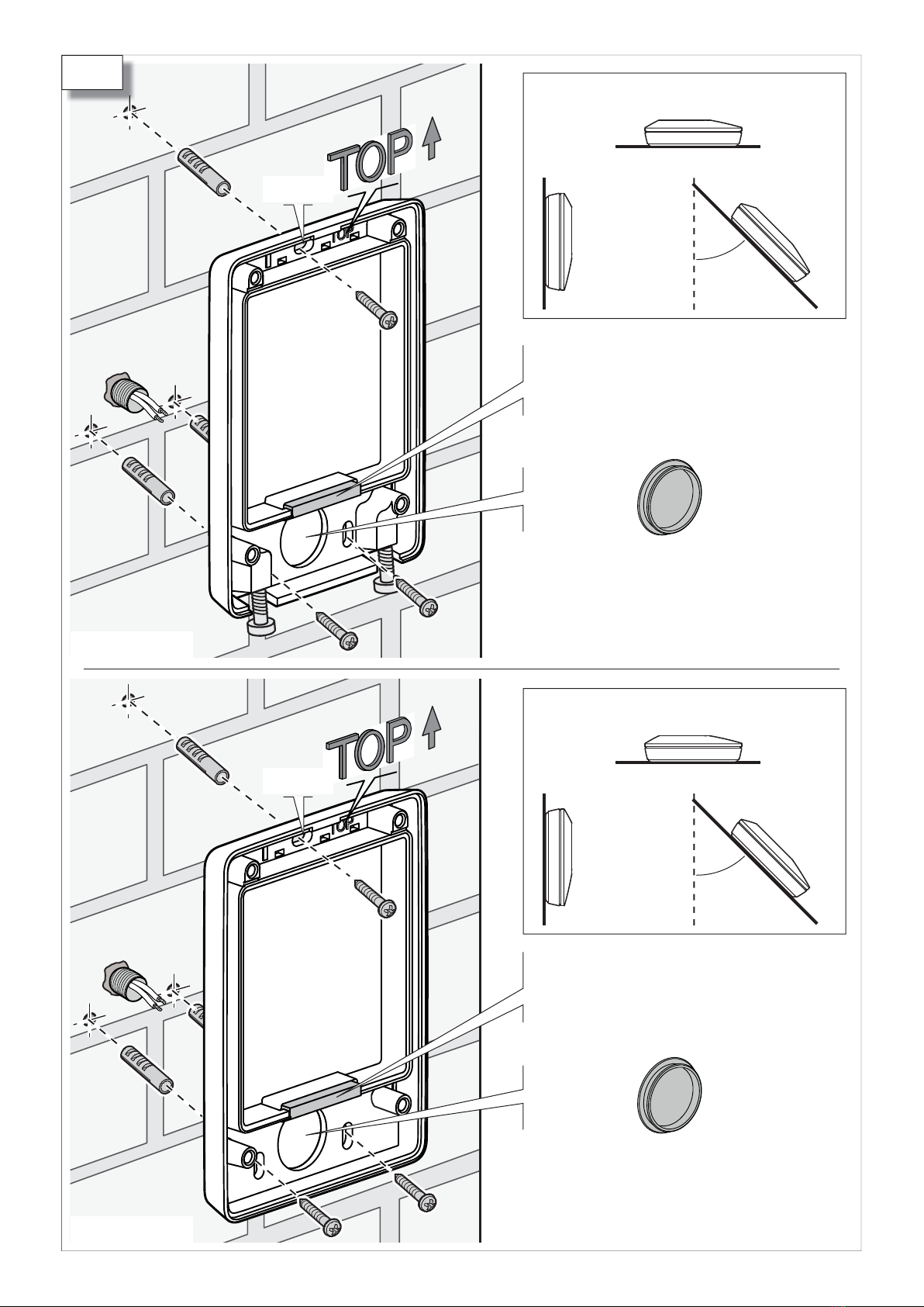
1. Prepare the connecting cables and install the
base. Follow the instructions in 1.
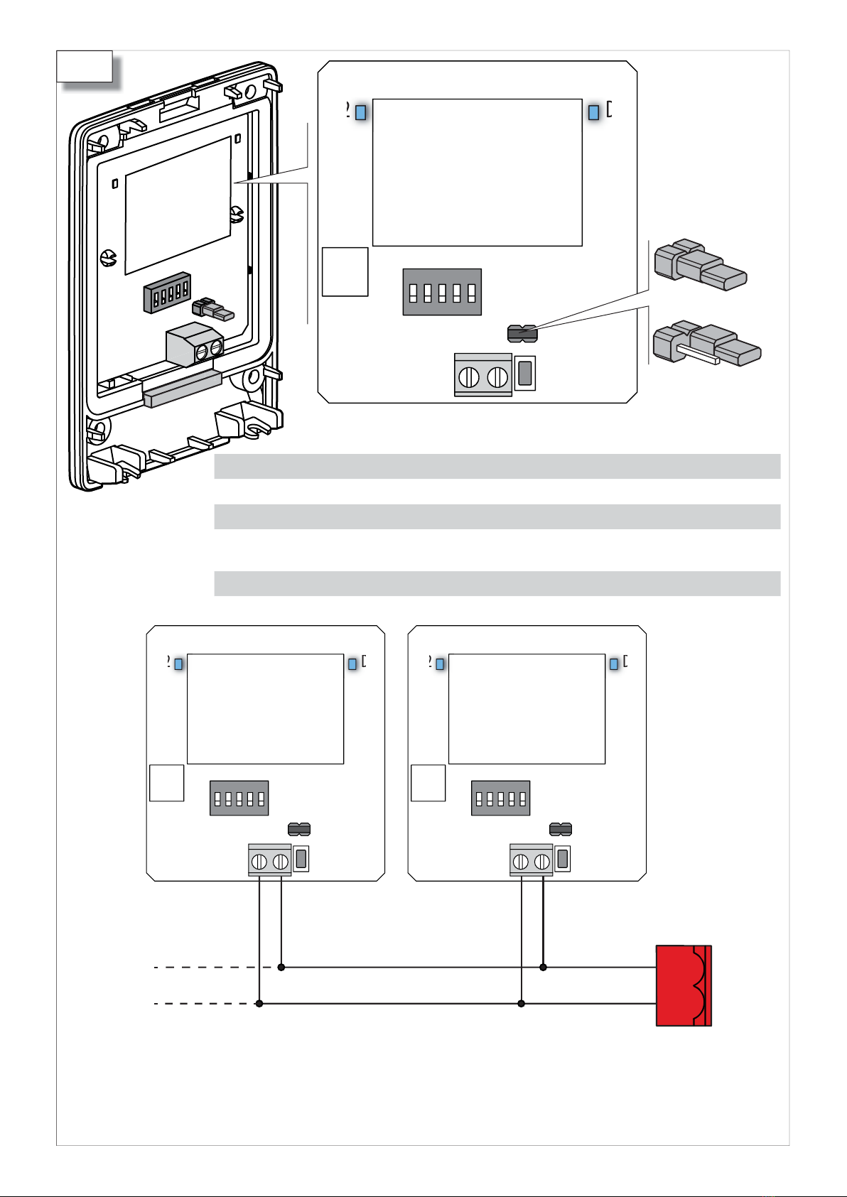
2. Connect the XTR B to the BUS 2easy terminals
of the board. Follow the instructions in 2.
3. Specify reader Aor B(6):
-J5 closed = XTR B (A)
-J5 open = XTR B (B)
4. Configure the DIP switches according to the
connection (§ 2.1 or § 2.2)
5. Turn power on to the board:
-The XTR B flashes once, then the LEDs turn
off: XTR B in standby.
6. Register the BUS 2easy (see the board or BUS-
RELAY interface instructions).
7. Carry out the first MasterTag storage procedure
according to the type of connection.
8. Make sure that all tags are working correctly for
all enabled commands.
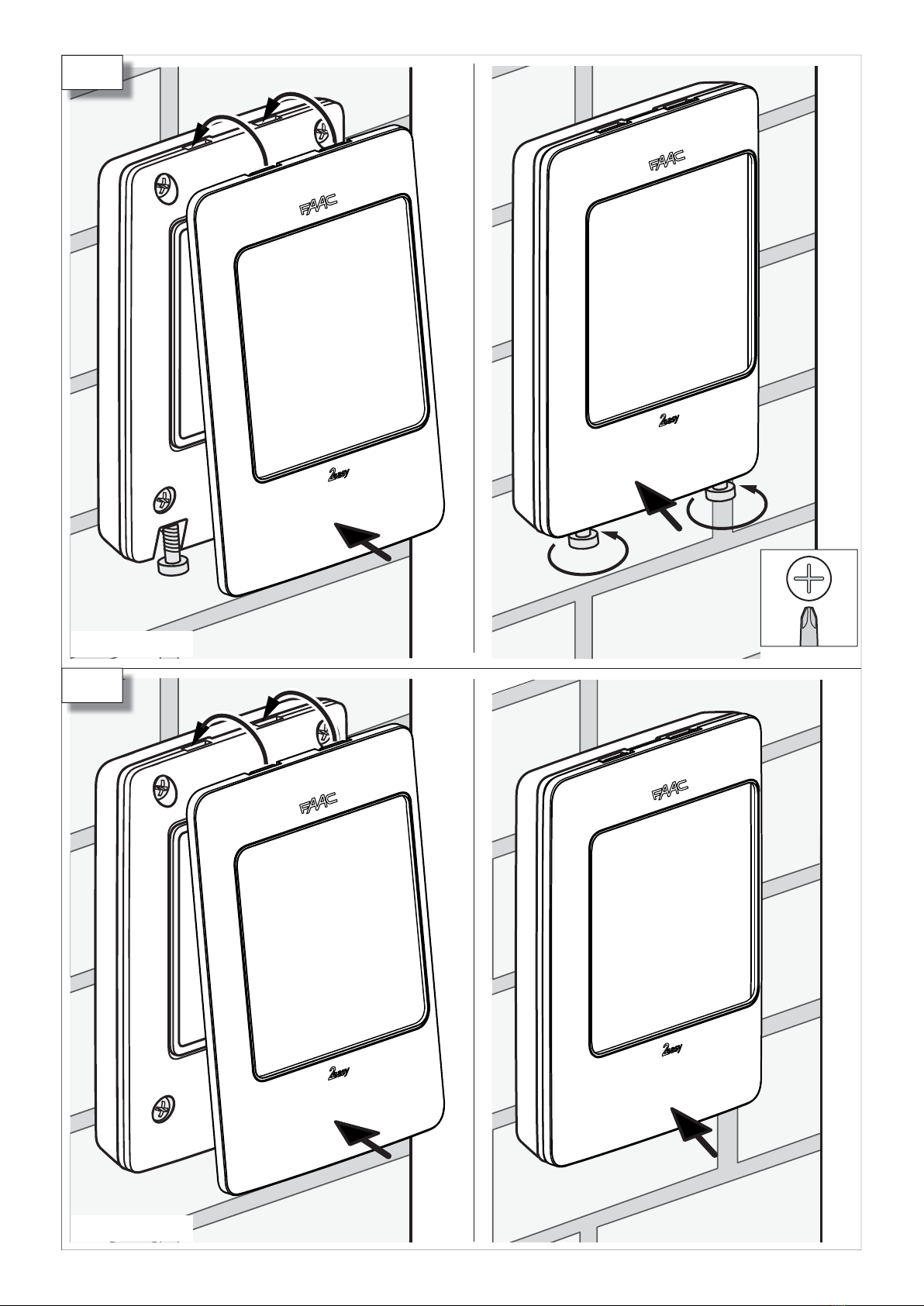
9. Fasten the body to the base (3) and put the
cover on (4- 5).
!The IPsealing gaskets in the base and in the
body must be fitted and intact.
SYMBOLS USED
Time Beep
LED off LED on
Flashing Fast flashing
1. XTR B
The XTR B Tag reader is included in the range of
FAAC BUS 2easy control devices. The range also
includes, for example, the XK10, XK11 and XKP B
(see catalogue).
The XTR B only recognises dedicated FAAC Tags (see
catalogue). A limited number of Tags can be ena-
bled. EachTagcanbeusedforanimpulsecommand
or a maintained action command.
!This device cannot be used as an emer-
gency stop.
This device cannot be used as the main-
tained command in the dead-man mode
of operation.
The XTR B can be connected to:
-Electronic board with BUS 2easy
-XBR2 BUS-RELAY interface
-XBR4 BUS-RELAY interface
When the XTR B is switched on, it automatically
recognises the type of connection.
Each tag always transmits two distinct codes: A
and B. The position of the jumper on the reader
determines whether the reader recognises code A
or code B (6). In this way, aTag can be enabled
with code A on one system and code B on another
system. Example: ATagenabledwithcodeAonthe
XTR B of a condominium entrance and with code B
on the XTR B of a private entrance.
The boards with BUS 2easy that are compat-
ible or incompatible with the XTR B are indicated
below. Some boards are compatible only if the
firmwarehasbeenupdatedto theversionsindicated
(FW)orlater(refertotheinstructionsoftheupdated
boards) The boards with BUS 2easy that are not
listed are compatible with any FW version.
Compatible boards [revision] FW
E045 [previous to 1L] 1.7
E045 [1L and later] 3.2
E145 [previous to 1R] 2.0
E145 [1R and later] 3.2
E124 [all] 3.2
E721 [all] 2.9
624BLD [all] 2.1
E680 [all] 2.1
JE275 [all] 2.1
Incompatible boards:
E700, E720, E024, E391, E012S, E850.

XTR B 3
ON
1 2 3 4 5
DIP 5 = OFF
ON
1 2 3 4 5
DIP 5 = ON
1 = ON ; 0 = OFF
11 Command mode
2.1 CONNECTING TO THE BOARD WITH BUS 2EASY
Configure the DIP switches on the reader to specify the operating mode (1 command or 2 commands) and
define the commands. To activate Command 1 or Command 2, see § 7 Usage.
CONFIGURING THE DIP SWITCHES
-DIP switch 5: 1 command or 2 command operating mode
-DIP switches 1-4: commands that the XTR B transmits to the board
Check the configuration of 1and 2in the board instructions. According to the type of board,
some configurations may not be used or correspond to different commands.
!For each control device connected to the BUS 2easy line, position the DIP switches so that a com-
mand is used only on one device.
In order to add an XTR B to an existing system you must know which commands are already used
on the other BUS 2easy devices that are present. See the instructions for the devices that are
already installed in order to identify which commands are already used. For future reference, you
canmakeanoteofthecommandsofalltheinstalleddevicesinthetableattheendofthismanual.
The configuration of BUS 2easy Photocells, or BUS 2easy Safety Edges does not interfere with the
control devices.
22 Command mode
DIP switch
1 2 3 4
Command 1
0 0 0 0 Open A_1
0 0 0 1 Open A_2
0 0 1 0 Open A_3
0 0 1 1 Open A_4
0 1 0 0 Open A_5
0 1 0 1 Stop
0 1 1 0 Stop NC*_1
0 1 1 1 Stop NC*_2
1 0 0 0 Close
1 0 0 1 Open B_1
1 0 1 0 Open B_2
1 0 1 1 Open B_3
1 1 0 0 Open B_4
1 1 0 1 Open B_5
1 1 1 0 not used
1 1 1 1 not used
DIP switch
1 2 3 4
Command 1 Command 2
0 0 0 0 Open A_1 Open B_1
0 0 0 1 Open A_1 Open B_2
0 0 1 0 Open A_1 Stop
0 0 1 1 Open A_1 Close
0 1 0 0 Open A_2 Open B_1
0 1 0 1 Open A_2 Open B_2
0 1 1 0 Open A_2 Stop
0 1 1 1 Open A_2 Close
1 0 0 0 Open A_3 Open B_3
1 0 0 1 Open A_3 Open B_4
1 0 1 0 Open A_3 StopNC*_1
1 0 1 1 Open A_3 Close
1 1 0 0 Open A_4 Open B_3
1 1 0 1 Open A_4 Open B_4
1 1 1 0 Open A_4 StopNC*_2
1 1 1 1 Open A_4 Close
* StopNC, also generates a Stop when the XTR B is disconnected.

XTR B 4
4
SW2 SW2
1
2
3
FIRST STORAGE PROCEDURE
(board with BUS 2easy)
First MasterTag
Additional MasterTags
F I R S T S T O R AG E P R O C E D U R E ( B O A R D W I T H
BUS2EASY)
All Tags enabled during the First storage procedure
are Master tags.
The Master Tags allow additional tags to
be added.
The XTR B must be in standby. The memory must
be empty.
1. Press and release the button once.
-After2s, the XTR B will beeponce and flash once.
-It will flash for 20 s (storing enabled).
2. Bring the firstTag up to the reader.
-The XTR B will beep once and the LEDs will come
on for 2 s: theTag is enabled.
-Flashing will resume for 10 s (storing enabled).
3. Repeat step 2for furtherTags.
4. To finish, let 10 s pass without bringing any
new Tags up to the reader (or press the button
immediately).
-The LEDs turn off: XTR B in standby.
Errors during storage process Solution
Atstep 1the XTR B signals an er-
ror and switches off in standby:
the button has been pressed
more than once
Repeat the pro-
cess correctly
At step 1, the XTR B signals an
error and turns off in standby:
the memory is not empty
Carryoutthe“Add
Tag”or “Total De-
letion”process
At step 3, the XTR B signals an
error,thentheLEDsturnoff:the
Tag has not been stored
Carryoutthe“Add
Tag”process
ERROR warning: 5 beeps and 5 flashes in
quick succession. timeout withoutTag: END
...20s MAX
1+2 s: Tag OK , 10 s (timeout)
1+2 s: Tag OK , 10 s timeout
...10s MAX
2 s 1() , 20 s (timeout)

XTR B 5
ON
1 2 3 4 5
ON
1 2 3 4 5
2.2 CONNECTING TO THE BUS-RELAY INTERFACE
ConfiguretheDIPswitchesonthereadertoassignanIDandtheoperatingmode(1commandor2commands)
(3). To activate Command 1 or Command 2, see § 7 Usage.
-With the XTRBin1commandmode,eachTagisenabledononlyonerelay,whichtheuseractivateswith
Command 1 (§ 7 Usage). The First storage procedure assigns eachTag to a specific Relay. All theTags
assigned to the same Relay belong to the same Group (4).
-With the XTR B in the 2 command mode, eachTag is enabled on 2 Relays. The user activates one Relay
with Command 1 and the other with Command 2. The First storage procedure assigns each Tag to a
specificpairofRelays. AlltheTags assignedtothesamepairofRelaysbelongtothesameGroup(4).
CONFIGURINGTHE DIP SWITCHES
-DIP switch 5: 1 command or 2 command operating mode
-DIP switches 1-2: device identification (ID)
-DIP switches 3-4: irrelevant
!Each control device connected to the BUS-RELAY interface must have a different ID.
Inorder toaddanXTR Btoanexistingsystem youmust knowtheIDs oftheotherBUS2easydevices
that are present. See the instructions for the devices already installed in order to identify the IDs
that have already been used.
For future reference, you can make a note of the IDs of the installed devices in the table at the
end of this manual.
The configuration of BUS 2easy Photocells, or BUS 2easy Safety Edges does not interfere with the
control devices
3Correspondence between Group / Relay
/ Command
4ID and operating mode
DIP switch ID
0 0 x x ID1
0 1 x x ID2
1 0 x x ID3
1 1 x x ID4
1 = ON ; 0 = OFF ; x = irrelevant
1 Command mode (DIP switch 5
= OFF)
Group 1 Relay 1 (Command 1)
Group 2 Relay 2 (Command 1)
Group 3*Relay 3 (Command 1)
Group 4*Relay 4 (Command 1)
2 Command mode (DIP switch 5
= ON)
Group 1 Relay 1 (Command 1)
Relay 2 (Command 2)
Group 2*Relay 3 (Command 1)
Relay 4 (Command 2)
*not available for the device with ID4
*not available for device with ID4
DIP 5 = OFF
1 command
DIP 5 = ON
2 commands

XTR B 6
4
SW2 SW2
1
2
3
F I R S T S T O R AG E P R O C E D U R E ( B U S - R E L AY I N -
TERFACE)
All Tags enabled during the First storage procedure
are Master tags.
The Master Tags allow additional tags to
be added.
TheXTRBmustbe instandby. Thememoryofthe
Group selected must be empty.
1. Select the group: press the button the same
number of times as the number of the Group
(eg.: Group 3, press 3 times).
-After 2 s, the XTR B will beep and flash the same
number of times as the number of the Group.
-It will flash for 20 s (storing enabled).
2. Bring theTag close to the reader.
-The XTR B will beep the same number of times as
the number of the Group and the LEDs will come
on for 2 s: theTag is enabled.
-Flashing will resume for 10 s (storing enabled).
3. Repeat step 2for furtherTags.
-The XTR B will beep once and the LEDs will
come on for 2 s after each additional Tag has
been enabled.
4. To finish, let 10 s pass without bringing any
new Tags up to the reader (or press the button
immediately).
-The LEDs turn off: XTR B in standby.
Repeat the procedure to enable another Group. At
step 1, assign an available Group.
Errors during storage process Solution
At step 1the XTR B signals an
error, then the LEDs turn off:
Group not available
Repeattheprocess
correctly
Atstep 1the XTR B, after a series
ofbeepsequaltothenumberof
the Group, the memorisation is
not active (LEDs on, No flashing
for 20 sec): the Group is already
stored in the memory
Carry out the“Add
Tag” process for
the group
At step 3, the XTR B signals an
error,thentheLEDsturnoff:the
Tag was not stored
Carry out the“Add
Tag” process for
the group
ERROR warning: 5 beeps and 5 flashes in
quick succession.
FIRST STORAGE PROCEDURE
(BUS-RELAY interface)
Ntimes (N = Group number)
FirstMasterTag of the Group
Additional Master Tag of
the Group
timeout withoutTag: END
...20s MAX
N +2 s: Tag OK , 10 s (timeout)
1+2 s: Tag OK , 10 s timeout
...10s MAX
2 s N() , 20 s (timeout)

XTR B 7
SW2
2
3SW2
SW2 ~ 20 s
2
2 s 1 ,10s , 10s ,
1+1 s ,
SW2 ~20 s
1
SW2 SW2
1
2 s N() ,
1, 10s , 10s , 1+1 s ,
Ntimes (N = Group number)
3. DELETING ALL TAGS
!This procedure permanently deletes allTags from memory.
The XTR B must be in standby.
TOTAL DELETION
DELETING a GROUP
1. Press and hold the button throughout the entire
sequence:
-After 2 s, the XTR B will beep once and starts
to flash for 10 s. The frequency of flashing then
increases for another 10 s. Finally the XTR B will
beep once and the LEDs turn on for 1 s: theTags
have been deleted.
-The LEDs turn off: XTR B in standby.
2. Release the button.
To interrupt the deletion procedure, release the
button before the beep in step 1. The LEDs turn
off: XTR B in standby.
4. DELETING A TAG GROUP
!This procedure permanently deletes all the Tags of the Group. The procedure is only active if the
XTRBisconnectedtoaBUS-RELAYinterface. Inothercases,carryoutthe“TotalDeletion”procedure.
The XTR B must be in standby.
1. Select the Group to delete: press the button
the same number of times as the number of the
Group (e.g.: Group 3, press 3 times).
-After 2 s, the XTR B will beep and flash the
same number of times as the number of the
Group. Then the LEDs will turn on steadily.
2. Press and hold the button throughout the entire
sequence:
-The XTR B will beep once and starts to flash for
10 s. The frequency of flashing then increases
for another 10 s. Finally the XTR B will beep
once and the LEDs turn on for 1 s: the Group has
been deleted.
-The LEDs turn off: XTR B in standby.
3. Release the button.
To interrupt the deletion procedure, release the
button before the beep in step 2. The LEDs turn
off: XTR B standby.
Note: If the XTR B signals an error at step 1and
then the LEDs turn off, carry out the“Total deletion”
procedure.

XTR B 8
New XTR B connected to the BUS 2easy board.
1. Press and release the button once.
-After 2 s, the XTR B will beep once and flash
once. Then it will flash for 20 s.
2. Press and release the button.
-The XTR B will beep once and the frequency of
the flashing will increase.
3. Within 10 s,bringupaMasterTag alreadystored
on the previous XTR B.
-The XTR B will beep once and the LEDs will
come on for 2 s.
4. Press the button to finish. The LEDs turn off:
XTR B in standby.
5. REPLACING THE XTR B
Intheeventofreplacement, youcanavoid havingtorepeatthestorageprocedureforallpreviously enabled
Tags. A MasterTag that was stored on the previous XTR B is required.
N e w X T R B c o n n e c t e d t o t h e B U S - R E L AY i n t e r f a c e
1. Select the group: press the button the same
number of times as the number of the Group
(eg.: Group 3, press 3 times).
-After 2 s, the XTR B will beep and flash the
same number of times as the number of the
Group. Then it will flash for 20 s.
2. Press and release the button.
-The XTR B will beep once and the frequency of
the flashing will increase.
3. Within 10 s,bringupaMasterTag alreadystored
on the previous XTR B.
-The XTR B will beep and flash the same number
oftimesasthenumberoftheGroupand theLEDs
will come on for 2 s, then flashing resumes.
4. Press the button to finish. The LEDs turn off:
XTR B in standby.
Repeat for allTag Groups present.
6. TROUBLESHOOTING
Indication Explanation Necessary action
TheLEDsdonotlightupwhen
it is switched on. Nopower supplyorthe XTR B
is not working. Check that the power supply is connected
and live. If there are no errors, replace
the XTR B.
When switched on, the LEDs
flash continuously. Connection error. Check the connection.
When switched on, the XTR B
gives an error. Corrupted data in memory. Carry out the“Total Deletion”and the“First
storage”procedure.
WhenaTagisbroughtcloseto
the XTR B it does not activate
the command.
NopowersupplyortheXTRB
is not working.
TheTag is not enabled.
Check that the power supply is connected
and live. If there are no errors, carry out
the“AddTag”procedure.
An enabledTag brought up to
the XTR B does not activate
the command, the LEDs flash
continuously.
DIP switch configuration
error. Check the configuration of the DIP switches
for all BUS 2easy control devices that are
connected in order to eliminate BUS 2easy
address conflicts.

XTR B 9
1+, ...2 s 2()
1
2
21
1
1
...
...
7. USAGE
7.1 1 COMMAND MODE
IMPULSE COMMAND1
1. With the XTR B in standby, bring the Tag close
to the reader for a moment. The command is
activated (the XTR B beeps once and the LEDs
turn on and off).
...2 s MAX
...2 s MAX
MAINTAINED ACTION COMMAND 1
1. With the XTR B in standby, bring the Tag close
to the reader and hold it there. The command
is activated (the XTR B beeps once and the LEDs
will come on steadily).
2. Move the Tag away when you wish to stop the
command (the LEDs turn off).
IMPULSE COMMAND2
1. With the XTR B in standby, bring the Tag close
to the reader and hold it there (the XTR B beeps
once and the LEDs come on steadily).
-after2s,theXTRBwillbeeptwiceandflashtwice
2. Move theTag away within 2 s . The command is
activated (the LEDs turn off).
7.2 2 COMMAND MODE
IMPULSE COMMAND1
1. With the XTR B in standby, bring the Tag close
to the reader (the XTR B beeps once the LEDs
come on steadily).
2. Move theTag away within 2 s. The command is
activated ( the LEDs turn off).
Command2
STOP
1 +Command1 , 1 +Maintainedactioncommand1 ,
1+Command1 ,
...~ 2 s

XTR B 10
3
2
2
1 +,
2s , 2 () ,
2s , 3 () ,
1
...~ 6s
1
...~ 9s
...
...
...
1 +,
2 s , 2 () ,
2 s , 3 () , ,
3 s
1 ,
MAINTAINED ACTION COMMAND 1
1. With the XTR B in standby, bring the Tag close
to the reader and hold it there (the XTR B beeps
once and the LEDs come on steadily).
-after 2 s, the XTR B will beep twice and flash
twice.
-after 2 s, the XTR B will beep 3 times and flash 3
times, then the LEDs will come on steadily
-after 3 s, the maintained action command is
activated
2. Move the Tag away when you wish to stop the
command (the LEDs turn off).
MAINTAINED ACTION COMMAND 2
1. With the XTR B in standby, bring the Tag close
to the reader and hold it there (the XTR B beeps
once and the LEDs will come on steadily).
-after2s,theXTRBwillbeeptwiceandflashtwice
-after 2 s, the XTR B will beep 3 times and flash 3
times, then the LEDs will come on steadily
2. Move the Tag away within 2 s, and bring it back
to the reader within 5 s. The maintained action
command is activated ( the XTR B flashes once).
3. Move the Tag away when you wish to stop the
command (the LEDs turn off).
STOP
STOP
2 s MAX 5 s MAX
Maintained action command 1
Maintained action command 2

XTR B 11
3
4
5
1
2
1
>5 s
2
- MASTER - SLAVE
4
6
<5 s
2 () ,
~ 5 s
8. ADDING TAGS
This procedure allows additionalTags to be enabled
subsequently to the first storage procedure.
You must have a Master Tag that has already been
stored and be close to the reader (without having to
open it). If the XTR B is connected to a BUS-RELAY
interface, use a MasterTag of the required Group.
Tags can be added as either Master or Slave tags.
Slave tags cannot be used to enable the
addition ofTags.
ADDING MASTER TAGS
The XTR B must be in standby.
1. Bring a Tag that has NOT been stored up to the
reader and wait for about 5 s:
-The XTR B will beep twice and flash twice, then
the LEDs will come on steadily.
2. Move theTag away.
3. Bring the previously stored MasterTag up to the
reader within 10 s.
-The LEDs still remain steady, the XTR B will
BEEP once.
4. Move the MasterTag away within 5 s.
-It will flash for 10 s (storing enabled).
5. Bring the Tags to add up to the reader in se-
quence, within 10 s of each other. The XTR B
beeps once and the LEDs turn on for 1 s for each
Tag added.
6. To finish, let 10 s pass without bringing a new
Tag up to the reader.
-The LEDs turn off: XTR B in standby.
ADDING SLAVE TAGS
Follow the previous procedure but at step 4, wait
until the XTR B beeps twice before moving the
MasterTag away.
9. MAINTENANCE
CleantheoutersurfacesonlywithasoftclothDonot
use detergents or oils.
ADDINGTAGS
Master Tag already
stored
Tag NOT stored
Tag to add
timeout withoutTag: END
... 10 s (timeout)
... 10 s MAX
10 s (timeout)
1+ 1 s: Tag OK , 10 s timeout

XTR B 12
Dispositivo • Device • Dispositif
• Vorrichtung • Dispositivo •
Inrichting
1
Comando • Command •
Commande • Steuerung
Comando • Commando
2
Comando • Command
Commande • Steuerung
Comando • Commando
ID
Table of contents
Popular Cash Counter manuals by other brands

CEBEK
CEBEK CD-9 manual

HYOSUNG
HYOSUNG MONiMAX5100T Operator's manual

Bulldog Security
Bulldog Security IncuCount RSIC150 quick start guide

Lofrans
Lofrans GALAXY 703 Installation and user manual

Baumer
Baumer NE210 operating instructions

DR. JOHANNES HEIDENHAIN
DR. JOHANNES HEIDENHAIN VRZ 560 operating instructions