Face KBS1E Operation instructions

D112 EN –2021 05 01
2
www.facespa.it
INDEX
Subject
Page
1. Introduction
2
2. Technical data
3
3. Sliding doors break-out system
4
4. Side walls break-out system
10
1. INTRODUCTION
The break-out systems for sliding doors made from FACE are both available in kit and assembled into Metra frames NC50I, as
indicated in the sales list.
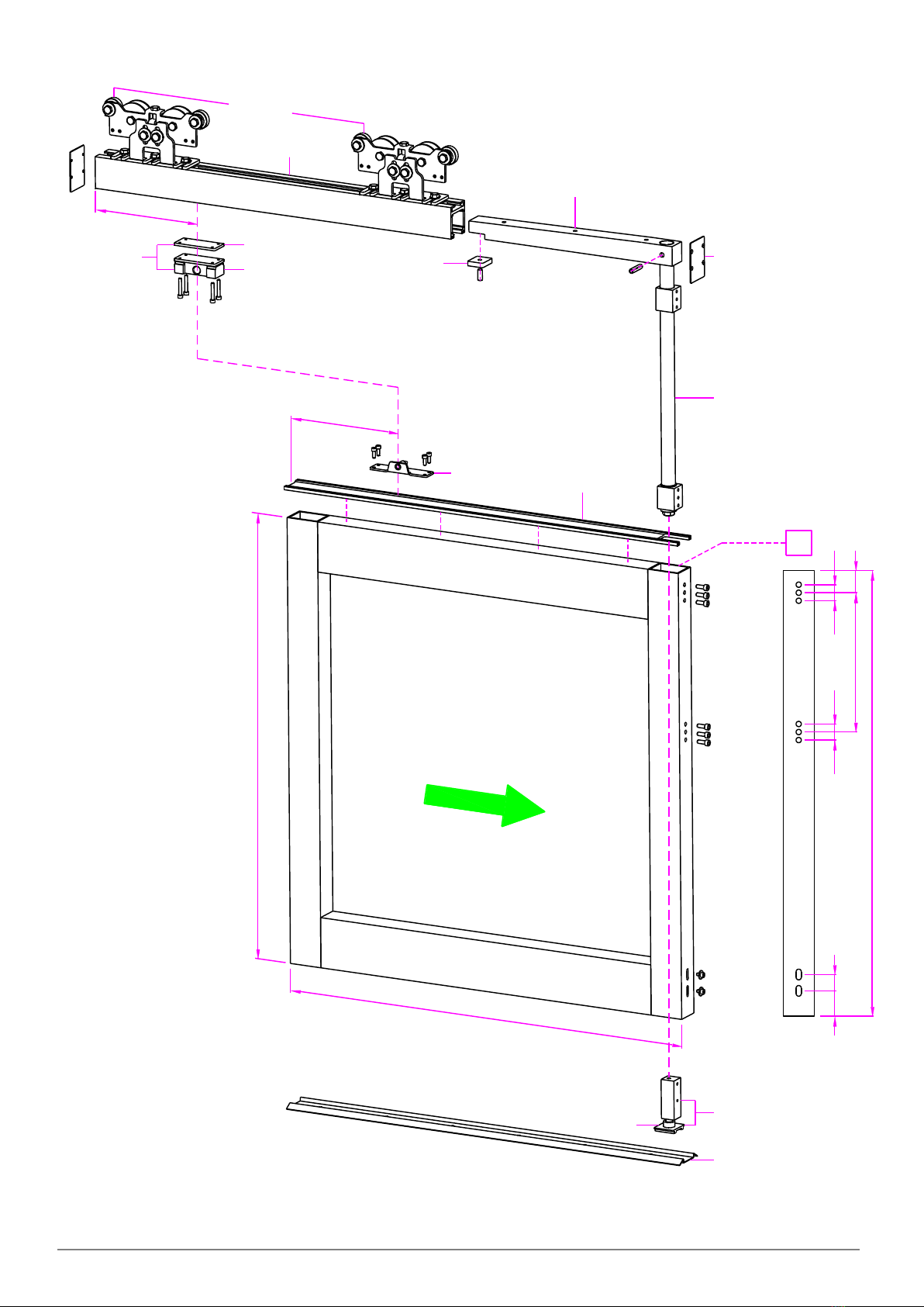
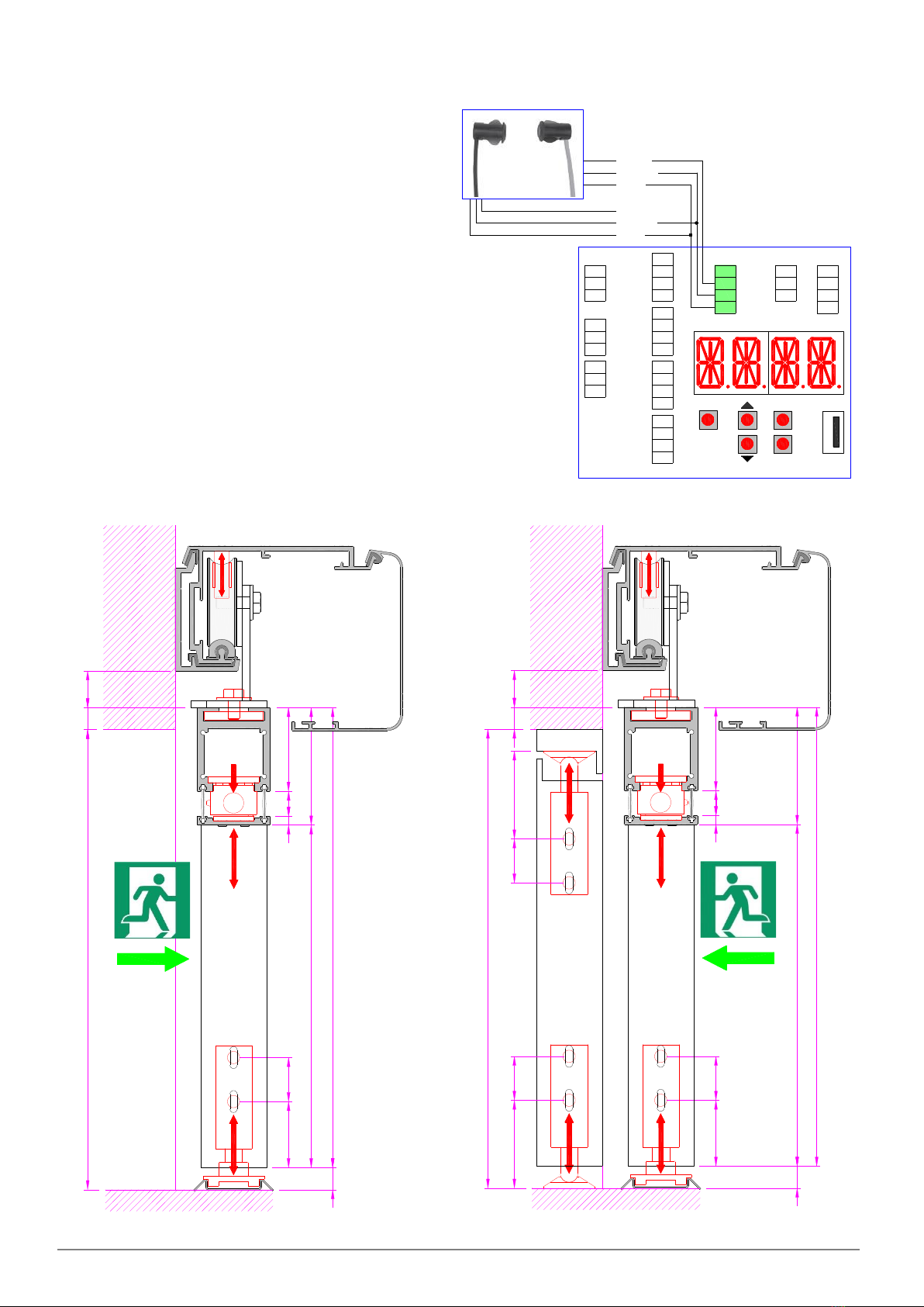
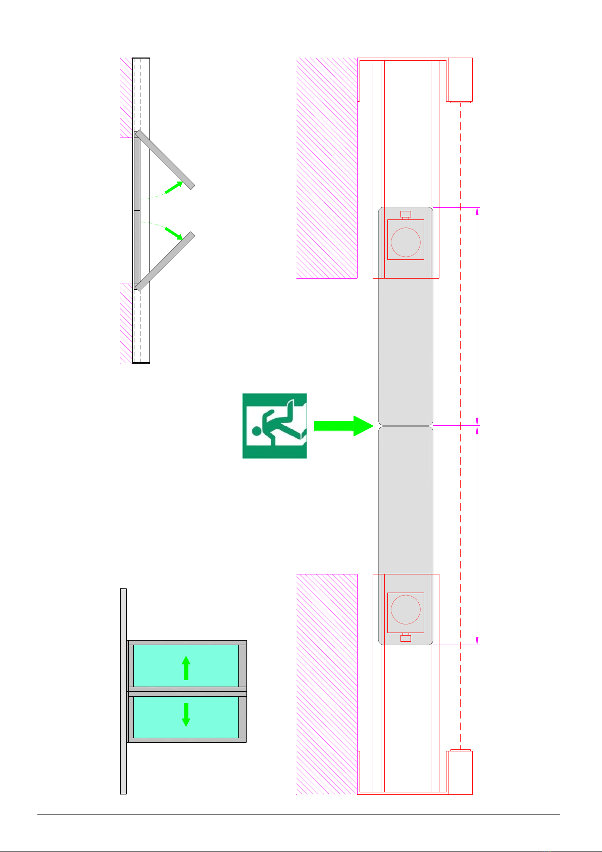
This manual provides the instructions to perform the assembly of the KBS1E break-out device for sliding door and KBS1D
break-out device for side wall, for Metra frames NC50I or for frames with similar size and of equivalent stability.
1.1 EC MARKING AND EUROPEAN DIRECTIVES
Break-out systems of the sliding doors and side walls are used in automatic doors for escape routes and
emergency exits. These automatic doors complete of break-out system, must comply with the European
standard EN 16005 and are CE-marked in accordance with the Machinery Directive (2006/42/EC).
Break-out systems of the KBS1E sliding doors and KBS1D side walls, in conjunction with the FACE
automation model SL5A and SF50 frame system (corresponding to the NC50I Metra systems), are approved by the Prima
Ricerca & Sviluppo S.r.l. laboratory and the test report is available at www.facespa.it in Download area.
All data and information contained in this manual have been drawn up and checked with the greatest care. However FACE
cannot take any responsibility for eventual errors, omissions or inaccuracies due to technical or illustrative purposes.
FACE reserves the right to make changes and improvements to their products. For this reason, the illustrations and the
information appearing in this document are not definitive.
This edition of the manual cancels and replaces all previous versions. In case of modification will be issued a new edition.

D112 EN –2021 05 01 3 www.facespa.it
2. TECHNICAL DATA
Technical data Sliding door Side wall
Kit device code KBS1E, KBS1E11 KBS1D
Maximum Height Hm = 2400 mm
Note: the measure Hm includes the height of break-
out profiles equal to 80 mm.
Hs = 2400 mm
Maximum width Lm = 1100 mm (code KBS1E11)
Lm = 1400 mm (code KBS1E)
Ls = 1600 mm
Minimum width Lm = 600 mm -
Maximum weight 120 kg x 0,8 m
100 kg
Sliding doors fixing to the
carriages
Use at least 2 screws per carriage (see ref. A in the
figure).
-
Upper wheels on
automation carriages
Add the second upper wheel on each carriage (code
5140), already included in the kit KBS1E and KBS1E11
code (see ref. B in the figure).
-
Hinges for the break-out
of the side wall
- The hinges for the break-out of the
side wall, are not included in the kit
KBS1D code, but they are part of the
frame (see ref. C in the figure).

D112 EN –2021 05 01
4
www.facespa.it
3. SLIDING DOORS BREAK-OUT SYSTEM
3.1 ASSEMBLY PROCEDURE FOR KBS1E KIT
Assemble the components in the kit KBS1E on the sliding door as shown below.
The vertical sizes of the leaf are indicated in Fig. 4. The horizontal sizes of the leaf are indicated in Fig. 6.
Note: the KBS1E kit break-out is designed to be assembled on the sliding doors in which the vertical profile has a minimum
chamber of 30 x 33 mm.
Step
Ref.
Description
1
B
Insert the pole (L) into the hinge pole (B) using the 8 x 35 mm elastic pin.
2
-
Make nr.6 holes d.6,5mm, on the vertical profile of leaf for attaching the hinge pole (B), respect the
measurements shown in Figure 1.
3
-
Make nr.2 slots d.5x15mm, on the vertical profile of leaf for attaching the lower pin (C), respect the
measurements shown in Figure 1.
4
A
Cut profile (A) and their brushes to measure Lm, and secure it at the top of the leaf, by screws not supplied
by us.
Note: in case of doors with 2 leaves, it’s preferable to cut the profile few millimetres longer (Lm +2), to cover
the gap which is determined in the upper part of the doors closed position.
5
B
Insert the hinge pole (B) in vertical profile and secure with the provided screws, in correspondence of the
drilled holes in step 2.
Note: lubricate the hinge pole before insert.
6
C
Insert the lower pin (C) in vertical profile and secure using the supplied screws, in the slots made in step 3.
7
D
Cut profile (D) and their brushes to measure Lm, insert it into the hinge pole (B) and secure with the provided
screws.
Note: in case of doors with 2 leaves, it’s preferable to cut the profile few millimetres longer (Lm +2), to cover
the gap which is determined in the upper part of the doors closed position.
8
E
Secure the coupling pin (E) on the profile (A) at the top of the door, respect the measurements shown in
Figure 1.
9
F
Insert the coupling pin (F) on the profile (D), using the provided screws, respect the measurements shown in
Figure 1.
10
G
Fix the heads (G) to the profile (D) with the provided screws.

D112 EN –2021 05 01
5
www.facespa.it
FIGURE 1: KBS1E assembly drawing

D112 EN –2021 05 01
6
www.facespa.it
3.2 INSTALLATION AND ADJUSTMENT PROCEDURE OF THE BREAK-OUT MOBILE LEAF
Step
Ref.
Description
1
H
Cut the sliding guide (H) to measure Lm (or higher), and attach it to the floor, as shown in the drawings of the
various types of door available in this manual, with screws not supplied by us.
2
K
Fix the leaf to the automation carriages, using at least 2 fixing screws, and add the second upper wheel (K) on
each carriage.
3
C
Adjust the pressure of the lower pin (C) on the sliding guide (H), as shown in fig. 2.
4
B1
To level any collapse of the break-out leaf, proceed as shown in fig. 2 and as indicated below:
- Loosen the B2 and B3 screws,
- Tighten the B1 screw until you get the levelling of leaf,
- Tighten the B2 and B3 screws.
5
F
Adjust the force necessary for the break-out of the leaf, as shown in fig. 2.
- To increase/reduce the manual force to break-out leaf, tighten/loosen the screw on the side of the coupling
pin (F);
- if you want to further reduce the manual force to break out leaf, you can increase the measurement of 150
mm to fixing the coupling pin (E) and (F).
Note: verify that the force required to break-out every door does not exceed the value of 220N, as required
by the EN 16005 European standard.
6
-
Fix the PH3 photocell on wall at the top, through the KPH1E support, so that the break-out of the leaf is
detected by the photocell, as indicated in Figure 6.
7
-
Make the electrical connections of the PH3 photocell to the electronic control 5CB01, as shown in Figure 3.
8
J
Apply on the leaf, in a visible location and in the direction of the break-out, the label supplied indicating the
emergency exit, as illustrated in Figure 2.
FIGURE 2: KBS1E adjustments

D112 EN –2021 05 01
7
www.facespa.it
FIGURE 3: Electrical connection of PH3 photocell and 5CB01 electronic control
Menu setting: ADV > STG1 = STOP.
Connect the emitter, using the black cable supplied to the
terminals of electronic control as follow:
blue wire = terminal 0
brown wire = terminal 1
black wire = do not connect
Connect the receiver, using the grey cable supplied to the
terminals of electronic control as follow:
blue wire = terminal 0
brown wire = terminal 1
black wire = terminal G1 (remove 1-G1 jumper)
FIGURE 4: KBS1E vertical sizes
FIGURE 5: KBS1D vertical sizes

D112 EN –2021 05 01
8
www.facespa.it
FIGURE 6: KBS1E horizontal sizes

D112 EN –2021 05 01
9
www.facespa.it
FIGURE 7: KBS1D horizontal sizes

D112 EN –2021 05 01
10
www.facespa.it
4. SIDE WALLS BREAK-OUT SYSTEM
4.1 ASSEMBLY PROCEDURE FOR KBS1D KIT
Assemble the components in the kit KBS1D on the side wall as shown below.
The vertical size of the leaf are indicated in Fig. 5. The horizontal size of the leaf are indicated in Fig. 7.
Note: The KBS1D break-out kit is designed to be assembled on side walls provided with hinges for the break out.
Step
Ref.
Description
1
A
Make 2 slots d.5x15mm, on the vertical profile of side wall for attaching the upper pin, as shown in Figure 8.
Insert the upper pin (A) in the vertical profile and secure using the supplied screws in the slots.
2
A
Make 2 slots d.5x15mm, on the vertical profile of side wall for attaching the lower pin, as shown in Figure 8.
Insert the lower pin (A) in the vertical profile and secure using the supplied screws in the slots.
3
B
Fix the upper bracket (B) to the top edge profile, at the upper pin (A), by screws not supplied by us.
4
B
Fix the lower bracket (B) to the floor, at the lower pin (A), by screws not supplied by us.
5
C
If necessary, fix protection (C) to the side wall, using the provided screws, respect the measurements shown
in Figure 8.
Note: the protections (C) avoid direct contact of the aluminium between the sliding leaf and the side wall,
when the sliding leaves and side walls are break out.
6
D
If necessary, fix the hook brackets (D) to the side wall, using the provided screws, respect the measurements
shown in Figure 8.
4.2 INSTALLATION AND ADJUSTMENT PROCEDURE OF THE SIDE WALL
Step
Ref.
Description
1
-
Make the installation of the frame system.
2
D
Move the sliding doors in closed position. If necessary, fix the hook brackets (D) to the sliding leaves in
correspondence of the hook brackets (D) already fixed to the side wall, using provided screws.
Note: the hook brackets (D) are hooked between them, and they prevent the break-out of the side wall when
the door is closed.
3
A
Adjust the release force of the upper pin (A) on the upper bracket (B), as shown in fig. 9.
4
A
Adjust the release force of the lower pin (A) on the lower bracket (B), as shown in fig. 9.
5
-
Make adjustments of sliding door indicated in the adjustment procedure, as illustrated in figure 2.
Note: verify that the required force to break-out every door does not exceed the value of 220N, as required
by the EN 16005 European standard.
6
-
Fix the photocell PH3 on the perimeter profile at the top, through the KPH1D support, so that the break-out
of the leaf and side wall are detected by the photocell, as indicated in figure 7.
7
-
Make the electrical connections of the PH3 photocell to the electronic control 5CB01, as shown in Figure 3.

D112 EN –2021 05 01
11
www.facespa.it
FIGURE 8: KBS1D assembly drawing

D112 EN –2021 05 01
12
www.facespa.it
FIGURA 9: KBS1D adjustments
FACE S.r.l. Viale delle Industrie, 74 –31030 Dosson di Casier –Treviso –Italy –www.facespa.it
This manual suits for next models
1
Table of contents
Other Face Door Opening System manuals