facelift nifty 170 sd User manual

shortform operating instructions
0800 52 15 95
www.facelift.co.uk
nifty 170 sd
self propelled access

This book is designed as a guide to enable you to start work quickly and safely. It is not intended
to replace the full manufacturer’s operating instructions (a copy of which should be with your
machine) which should be read and understood by anyone operating the machine.
SAFETY TIPS
In the unlikely event that your machine develops a fault
please contact the Facelift Tech Team on 01444 881100
ALWAYS
•Inspect your machine before use.
•Check all operations including ground controls.
•Check ground conditions.
•Check clearance from overhead obstructions (power
cables, building projections etc).
•Plan your task/job.
•Use sole boards under your outriggers at all times
regardless of ground conditions.
•Stabilise and level machine before use.
•Wear a safety harness connected to a suitable
anchorage point inside the platform.
•Operate all controls smoothly.
•Warn other people that you are there by means of
flashing lights, sign and cones.
•MAKE SAFETY YOUR No.1 PRIORITY.
NEVER
•Use an unsafe machine.
•Use an access platform to hoist loads like a crane.
•Overload cage/platform.
•Operate in strong winds (Check manufacturer’s
recommendation).
•Rest the cage on a structure or object to gain
extra support.
•Attach your safety harness to a structure outside of
the platform.
•Throw or drop anything from the platform.
•Use boxes, ladders or stand on handrails to gain additional
height, if you can’t reach, you need a bigger machine.
•Let an untrained person operate the access platform.
•Take unnecessary risks (hospitals and graveyards are
full of dead heroes!)
CONTENTS
Daily Safety Check List ..........................................1
Setting Up Procedures ..........................................1
Ground Control Operation ....................................1
Platform Control Operation ....................................2
Platform Pushbutton Controls Station....................3
Starting The Engine From The Platform ................3
Power System Changeover ..................................4
Driving Controls ....................................................4
Boom Controls ......................................................4
Emergency Controls ..............................................5
Notes ....................................................................5

1
DAILY SAFETY CHECK LIST
Before use each day and at the beginning of each shift the aerial
platform shall be given a visual inspection and functional test
including, but not limited to, the following:
1) Read and fully understand Operating and Safety Manual.
2) Check safety belts and hard hats.
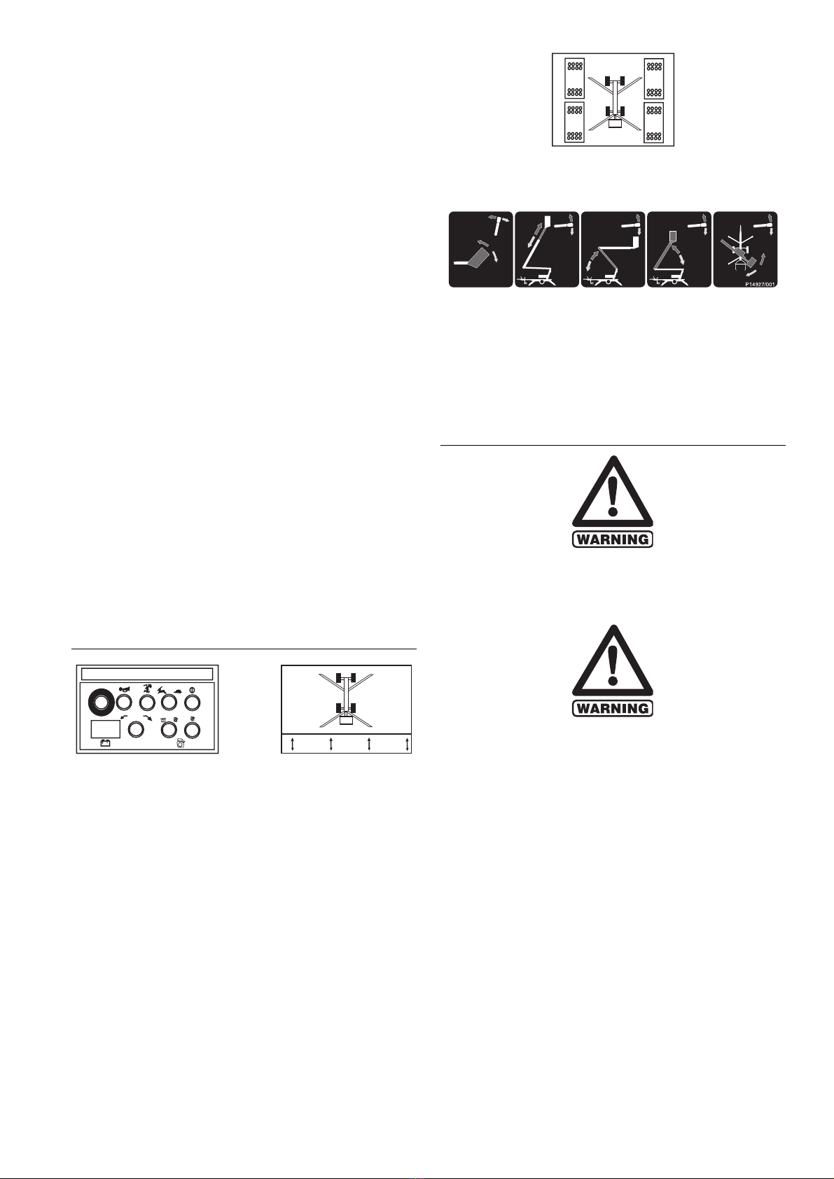
3) Check all decals and placards to see if in place and legible.
4) Check platform is securely fastened to platform support.
5) Check wheels and tyres.
6) Check outriggers (if applicable) for condition, microswitch
operation and security.
7) Check batteries for condition, cleanliness, connections and
electrolyte levels.
8) Check engine oil, fuel and coolant levels (if applicable).
9) Check installation of all guards, covers and boom clamps.
10) Check for loose, missing or damaged parts.
11) Check all hydraulic hoses and electrical cables and wiring.
12) Check hydraulic, fuel and air systems for leaks.
13) Do not exceed rated platform capacity 440 lbs (200kgs).
14) Check foot pedal for proper operation (if applicable).
15) Check all operating emergency controls – Select an area
free from obstructions and hazards. Exercise extreme
caution throughout the checking procedure especially when
checking brakes
16) Check operation of emergency system and jack recovery
17) Check brakes and all lights.
18) Check tilt sensor/alarm horn and beacons (if fitted).
19) Check high engine and/or high drive limit switches.
20) Check and refer to Operating and Safety Manual for further
daily/periodic checks and inspections.
SETTING UP PROCEDURES
FAILURE TO DEPLOY THE OUTRIGGERS CORRECTLY
COULD RESULT IN DEATH OR SERIOUS INJURY.
ALL MODELS
1) Read and fully comply with all safety precautions and
operating instructions in the Operating and Safety manual
and the warning decals on the machine.
2) Position Niftylift on firm, level ground. NEVER work with
base across or adjacent to any slope.
3) Position Niftylift, bearing in mind range of boom movement
so that any overhead obstruction or possible hazards such
as, but not limited to, power cables, telephone lines, drains,
man-hole covers, etc.
4) If the load bearing capacity of the ground is in any doubt
the machine must not be used.
5) Check wheels and cordon off area using appropriate
cones, barriers and flags.
6) Release boom travelling clamp.
7) Check all red emergency stops are not engaged i.e. fully out.
8) Ensure selector handvalve adjacent to ground control
station is turned fully down to outrigger/drive position.(for
four wheel drive machine grasp and hold duty selector.
Power will be available automatically).
9) From the cage control station depress and hold the green
power button or footswitch to give hydraulic power to the
outriggers and select the appropriate control lever. Note: No
power will be available if the booms are not in the boom rest.
10) Using the four outrigger control levers, (toggle switches on
4WD), lower each outrigger onto a firm level surface and
level machine base ensuring each outrigger foot is taking
equal weight with the wheels clear of the ground.
11) Check machine is level using spirit level on the base, visible
from the cage.
12) Change selector valve at drive/outrigger control station to
platform, i.e. turn fully up. (On four wheel drive machines
releasing the duty selector handle automatically returns the
machine to ‘platform’ operation).
13) The booms can now be operated from the ground or cage
control station by depressing and holding the green power
button. Note: If no power is available check each outrigger
is lowered and each footpad is taking weight.
14) Always lower booms before adjusting, raising, retracting or
moving outriggers in any way.
15) Never alter, modify or block any of the safety circuits on
the Niftylift.
GROUND CONTROL OPERATION
ALWAYS ALLOW THE ENGINE TO
WARM UP BEFORE OPERATING.
ALL MODELS
1) Ensure all red emergency stops are out.
2) Turn key switch at ground control station to ground (i.e.
fully down).
3) Ensure selector hand valve (if applicable) is turned to
platform position i.e. fully up.
4) Battery electric models go to step 10).
DIESEL ENGINE OR BI ENERGY MODELS
5) Turn duty selector in platform to BATT (Battery) or
ENG (Engine).
6) If BATT (Battery) is selected go to step 10).
7) If ENG (Engine) is selected go to step 8). for a COLD
ENGINE or step 9). for a WARM ENGINE.
8) COLD ENGINE. turn the main engine ignition switch (located
in RHS engine canopy) through ON to GL. This engages the
glow plug pre-heat system. Hold for 3-5 seconds then turn
key fully to ST (start) position and the engine will fire.

9) WARM ENGINE turn the main engine ignition switch
(located in RHS engine canopy) through ON to ST (start)
position and the engine will fire.
PETROL (GASOLINE) ENGINE OR PETROL
(GASOLINE)/ELECTRIC MODELS
5) Turn duty selector in platform to BATT (Battery) or
ENG (Engine).
6) If BATT (Battery) is selected go to Step 10).
7) If ENG (Engine) is selected go to Step 8). for a COLD
ENGINE or Step 9). for a WARM ENGINE.
8) COLD ENGINE. turn the engine fuel tap on and engage the
choke lever. Turn the main engine ignition through ON to ST
(Start) and the engine will fire. Return the choke lever to its
normal running position after the engine is started.
9) WARM ENGINE. turn the engine fuel tap on and turn the
main engine ignition through ON to ST (start) position and
the engine will fire.
ALL MODELS
10) Push and hold green power button.
11) Select function and operate handlevers in full accordance
with manufacturers operating and safety manual.
12) To return control to platform turn key fully clockwise to
up position.
13) When not in use return machine to stowed position, fully
raise and stow all outriggers, turn key to centre off position,
remove key and chock wheels.
EMERGENCY PROCEDURES
14) Push in red emergency stop to shut down all functions.
15) Use emergency hand pump to manoeuvre machine into a
safe position. Base or cage controls can be used whilst the
handpump is being operated. Only when the machine is
fully stowed should the flow be directed to the jack controls
in order to recover the jacks. Failure to follow this procedure
could result in serious injury or risk of death.
16) To swing booms fit a 1/2 inch drive socket to end of swing
worm gear and crank round manually.
BOOM FUNCTIONS
A) Push and hold green “Power Control” button.
1234
B) Select lever 1, 2, 3, or 4 for desired boom function.
1Operates Telescope UP for out DOWN for in.
(If applicable, Ground control of telescope function is
an option)
2Operates Lower boom UP for up DOWN for down.
3Operates Upper boom UP for up DOWN for down.
4Operates SLEW (Swing) UP for right DOWN for left.
ALWAYS ENSURE THE AERIAL PLATFORM IS ON A
FIRM LEVEL SURFACE AND THE AREA IS FREE OF ANY
OVERHEAD OBSTRUCTIONS.
ENGAGING THE RED EMERGENCY STOP BUTTON WILL
SHUT DOWN THE ENGINE, AND THE ELECTRIC
CIRCUIT PREVENTING OPERATION OF ANY FUNCTION.
PLATFORM CONTROL OPERATION
NEVER START THE NIFTYLIFT IF YOU SMELL PETROL
(GASOLINE), LIQUID PROPANE OR DIESEL. THESE
FUELS ARE FLAMMABLE.
BEFORE OPERATING THE NIFTYLIFT ENSURE THAT
EACH OPERATOR HAS READ AND FULLY
UNDERSTOOD THE OPERATING MANUAL. FAILURE TO
DO SO MAY RESULT IN DEATH OR SERIOUS INJURY.
ALL MODELS
1) Ensure all red emergency stops are out.
2) Turn key switch at ground control station fully up to
platform position.
3) Ensure selector hand valve (if applicable) is turned to
platform position i.e. fully up.
4) Battery electric models go to step 10.
DIESEL ENGINE OR BI ENERGY MODELS ONLY
5) Turn duty selector in platform to BATT (Battery) or
ENG (Engine).
6) If BATT (Battery) is selected go to Step 10).
7) If ENG (Engine) is selected go to Step 8) for cold engine or
Step 9) for a warm engine.
8) COLD ENGINE Turn the main engine ignition switch
(located in RHS engine canopy) to ON. Turn the ignition
switch in the cage to the left ‘Glo’ position and hold for 3-
5 seconds then turn key fully to right (start) position and the
engine will fire.
9) WARM ENGINE Turn the main engine ignition switch to
ON. Then turn ignition switch in the cage fully to the right
(start) position and the engine will fire.
2

3
PETROL (GASOLINE) ENGINE OR PETROL
(GASOLINE)/ELECTRIC MODELS ONLY
5) Turn duty selector in platform to BATT (Battery) or
ENG (Engine).
6) If BATT (Battery) is selected go to Step 10).
7) If ENG (Engine) is selected, ensure the fuel tap is turned to
the ON position and then go to Step 8) for cold engine or
Step 9) for a warm engine.
8) COLD ENGINE (From the ground only) turn the engine fuel
tap on and engage the choke lever. Turn the main engine
ignition through ON to ST (Start) and the engine will fire.
Return the choke lever to its normal running position after
the engine is started.
9) WARM ENGINE Turn the main engine ignition switch to
ON. Then turn ignition switch in the cage fully to the right
(start) position and the engine will fire.
ALL MODELS
10) Ensure key switch selector is turned to ON or BATT
(Battery) if applicable.
11) Depress foot switch or push and hold green power button.
12) Select function and operate hand levers in full accordance
with manufacturers operating and safety manual.
13) When not in use return booms to stowed position. Fully
raise and stow all outriggers. Turn key switch at ground
control to centre off position, remove key and chock wheels.
PLATFORM PUSHBUTTON
CONTROLS STATION
Fig. 1 Fig. 2
(BI-ENERGY MODEL SHOWN)
DRIVE AND BOOM FUNCTIONS
Situated at the top of Boom 1 (superstructure) is the 5 lever
drive/outrigger hand valve. These control the following functions:
Left hand lever: Two axis joystick for drive: Upwards for Forward,
Downwards for Back and Steer: Left for Left, Right for Right.
The remaining levers control jack deployment as indicated in
fig.2 (Mounted adjacent to the jack control position) Two wheel
drive machine only.
FOUR WHEEL DRIVE: JACK CONTROL
Situated adjacent to the single drive/steer joystick is the box
comprising the toggle switches controlling each stabiliser leg.
These operate individually to either lower or raise each leg and
provide the levelling function for the machine base.
IOII min max
POWER
CONTROL
HI/LO
DRIVE
TILT
ALERT
HORN
EMERGENCY
STOP 23
41
1234
RAISE
LOWER
BOOM CONTROLS
12345
Select lever 1, 2, 3, 4, or 5 for desired function.
Toggle switches 1,2,3 and 4 operate individual outrigger legs as
indicated on the adjacent label
STARTING THE ENGINE
FROM THE PLATFORM
NEVER START THE NIFTYLIFT IF YOU CAN SMELL
PETROL (GASOLINE), LIQUID PROPANE OR DIESEL.
THESE FUELS ARE HIGHLY FLAMMABLE.
****FOR COLD START PROCEDURES SEE PLATFORM
CONTROL OPERATION: STEP 8
A) Ensure main engine ignition located in RHS engine canopy
is turned to ON position.
B) Ensure that all EMERGENCY STOPS are not engaged (i.e.
must be fully out).
C) Ensure the key switch selector located at the ground
control station is turned to platform (i.e. fully up).
D) Ensure the duty selector in the platform is in the ENG
(Engine) position.
E) Turn ignition switch to the right (start) position and the
engine will now fire up.
F) The engine will automatically rev up if the booms are in
the stowed position and the green power control
pushbutton, or the footswitch, if applicable, is depressed,
thus allowing fast travel speed – when selected on the
Hi/Lo selector.
G) To shut down the engine from the platform simply turn the
duty selector to OFF or BATT (Battery) or in an emergency
depress the RED Emergency stop button.
2
3 4
1

POWER SYSTEM CHANGEOVER
ENGINE TO BATTERY
1) Engage any RED Emergency Stop button to shut down
the engine.
2) Re-set RED Emergency Stop button.
3) Turn the duty selector in the platform to BATT (Battery).
BATTERY TO ENGINE
1) Ensure all RED Emergency Stops are out.
2) Ensure main engine ignition switch located at the ground is
turned to ON.
3) Turn the duty selector in the platform to ENG (Engine).
4) Turn ignition switch to the right (start) position and the
engine will now fire up.
PETROL (GASOLINE) TO GAS
1) Locate petrol shut-off valve on carburettor, and turn petrol
to OFF position.
2) Run engine until all of the Petrol is exhausted, i.e. engine stops.
3) Open valve on gas bottle, introducing supply to the vapouriser.
4) Turn engine over until it fires, allow vapouriser to achieve
running temperature before using machine. If engine runs
erratically, check that all petrol has been used from bowl.
GAS TO PETROL (GASOLINE)
1) Turn gas off by shutting valve on the bottle – ensure that it
is fully closed.
2) Open fuel shut-off valve on engine carburettor, and allow it
to fill with petrol.
3) Turn engine over until it fires.
DRIVING CONTROLS
DO NOT OPERATE THE NIFTYLIFT WHILST ELEVATED
UNLESS ON A FIRM, LEVEL SURFACE FREE FROM ANY
POSSIBLE OBSTRUCTIONS OR HAZARDS BOTH AT
GROUND LEVEL AND OVERHEAD.
1) Check proposed route for possible hazards, obstructions
and personnel.
2) Depress footswitch located in platform floor (if applicable).
For four wheel drive machine grasp and hold the duty
selector handle.
3) Use Hi/Lo selector on platform pushbutton control station
to determine speed.
HIGH DRIVE – GIVES HIGH SPEED AND LOW GRADEABLITY
LOW DRIVE – GIVES LOW SPEED AND HIGH GRADEABILITY
4) Select drive joystick from hand lever controls (left hand
lever of five, situated at the drive/outrigger control position).
AUp for forwards
BDown for reverse
CLeft for steer left
DRight for steer right
The driving horn is activated by the button on the cage controls.
5) All control levers give a fully proportional response,
therefore the more the lever is moved away from the centre
(off) position the faster the function will become.
6) Maximum drive speed is only attainable when all booms are
fully stowed and the Hi/Lo selector is in the Hi position and
fast speed selected on the switch.
7) When driving with the booms fully stowed, the tilt alarm
is bypassed to allow the Niftylift to be driven in areas
where the slope exceeds the five degree working limit. In
normal operation the drive is therefore unaffected when
driven onto a slope in excess of five degrees, until the
outriggers are lowered and the booms are raised,
whereupon the drive would be disabled and the tilt alarm
sounds continuously.
8) Under no circumstances should any Niftylift SP series
machine be driven on slopes exceeding 25%, with the
booms fully stowed (30% for 4WD machine).
BOOM CONTROLS
1) Never exceed the maximum platform capacity of
440lb (200kg).
2) Check below, above and around platform for any
obstruction or hazards before operating any function
3) Depress the green power button or the foot switch located
in the platform floor (if applicable).
4) Select handlever controls marked 3, 4, 5.
Control 1 Operates Cage Swivel (optional)
Control 2 Operates Cage Levelling
FORWARD for (if applicable) forward
BACK for back
Control 3 Operates Telescope
UP for telescope out
DOWN for telescope in
Control 4 Operates Lower Boom
UP for up
DOWN for down
Control 5 Operates Upper Boom
UP for up
DOWN for down
Control 6 Operates Swing
UP for right
DOWN for left
IF ALARM SOUNDS -DESCEND IMMEDIATELY. THIS
MACHINE IS NOT ELECTRICALLY INSULATED. DO NOT
WORK WITHIN 3M (10FT) OF OVERHEAD CABLES
EXCEEDING 415 VOLTS.
4

5
EMERGENCY CONTROLS
GENERAL
CHECKING THE OPERATION OF THE EMERGENCY
CONTROLS EVERY DAY AND/OR BEFORE EACH SHIFT
IS AN ESSENTIAL PART OF THE OPERATORS DUTIES.
The operator and all ground personnel must be
thoroughly familiar with the location and operation of the
EMERGENCY CONTROLS.
IN THE EVENT OF AN INCAPACITATED OPERATOR.
Turn key switch selector at ground control station to ground (i.e.
fully down). Lower on ground controls as detailed under Section:
Ground Control Operation.
IN THE EVENT OF MACHINE FAILURE.
The first recourse with all bi-energy machines is to switch to the
alternate power source, recover the machine and fix the original
problem. In the unlikely event of a fault which prevents either
system from providing hydraulic flow, the machine can still be
brought down to the rest position with the use of the emergency
hand pump. The emergency hand pump is capable of
manoeuvring the machine fully in any direction in order to stow
the booms back in the transit position. Moving the duty selector
to the alternate position will allow the ground operator to recover
the jacks. Only when the machine is fully stowed should the
controls be used to raise the outriggers. Failure to follow this
procedure could result in serious injury or risk of death. Once
completed, releasing the emergency hand pump will allow the
system to reset ready for normal operation.
In the specific case of the four wheel drive machine, the
emergency hand pump feed will default to the platform
operation at all times. Once the booms have been recovered, it
is possible to redirect the flow to the drive and outrigger circuit
by using the duty selector valve at the top of Boom 1. Drive and
steer control is available for the emergency hand pump, but if
the outriggers are to be recovered the dead head dump manual
override valve needs to be closed to prevent the hydraulic flow
from returning directly to tank. This is situated beneath the
canopy adjacent to the dump solenoid and is tie wrapped to
prevent unauthorised operation. (See Drawing no D80230, item
37). If electrical power has been lost, it will be necessary to
manually hold the solenoid for each stabiliser leg to direct the
hydraulic flow to the cylinders. Once completed the dead head
dump manual bypass valve MUST be reset in the open position
in order to re-establish the machine safety interlocks. Failure to
do so will render the machine in a potentially dangerous position
TO ROTATE PLATFORM IN AN EMERGENCY.
Fit 1/2 inch drive socket on to end of slew worm gear and crank
round manually.
NOTES

When hiring access equipment we
strongly recommend taking
advantage of one of our one day
operator training courses
As
Facelift
is an accredited
IPAF (Independent Powered
Access Federation) training
centre you can be sure that
your staff will be trained to
a high standard and
receive an internationally
recognised qualification.
Courses can take place on your own premises or at one of our training
centres, situated in Hickstead, Iver, Southampton and Liverpool.
We can train your personnel on any of the following equipment:
(SL) Scissor Lift
(SPB) Self Propelled Boom
(VMP26) Truck/Van mounted to 26m
(VMP200) Truck mounted over 26m
(VPP) Vertical Personnel Platform
(TP) Trailer/Push around
The one day course* covers site safety, practical demonstration, sole
usage and site risks and includes a theory test.
*(two day course for VMP200)
Successful candidates are issued with the IPAF PAL card, widely
accepted by both the CITB and Health And Safety Executive.
For further information or to arrange a training course call us today on:
0800 0 72 55 72
operator training centre
0800 52 15 95
www.facelift.co.uk
Table of contents
Other facelift Lifting System manuals
Popular Lifting System manuals by other brands

KEBCO
KEBCO COMBIVERT F4-F instruction manual

ARJO HUNTLEIGH
ARJO HUNTLEIGH Malibu Sovereign Maintenance and Repair Manual

Bend-Pak
Bend-Pak XP Series Installation and operation manual

Bend-Pak
Bend-Pak HD-9STX Installation and operation manual

PRO LIFTS
PRO LIFTS VMB TE-071 operating instructions

Smart Lift
Smart Lift SL 408 user manual

WCP
WCP GreyT Elevator V3 user manual

R. Beck Maschinenbau
R. Beck Maschinenbau HS 1000 FH operating manual

Dhollandia
Dhollandia DH-RB 05.02 Series Service and maintenance user manual

WITTUR
WITTUR WGG-29.1 operating instructions

Ergoswiss
Ergoswiss SL compact Operating instruction

Nußbaum Hebetechnik
Nußbaum Hebetechnik 2.30 SL E Operating Instruction and Documentation