Factory Five Racing Hot Rod Coyote User manual

Factory Five Racing, Inc.
DO NOT DUPLICATE CONFIDENTIAL INFORMATION AND PROTECTED UNDER U.S. COPYRIGHT LAWS
2012 FACTORY FIVE RACING, INC.
Company/instructions
Part Number: 33871 Revision: D Effective Date: 6/4/12 By: J. INGERSLEV
Document Type (indicate):
Bill of Material Drawing (may be attached) Specification
Assembly Instructions Operating Procedure Other
Hot Rod Coyote Engine
Installation Instructions
Parts needed..............................................................................................................................................................................2
Ford Racing Parts..................................................................................................................................................................2
Ford Motor Co. Parts.............................................................................................................................................................3
Summit Racing......................................................................................................................................................................3
Fuel System .......................................................................................................................................................................3
Air Intake System ..............................................................................................................................................................3
Other vendors........................................................................................................................................................................3
Autozone ...........................................................................................................................................................................3
Supplies.....................................................................................................................................................................................3
Information ...............................................................................................................................................................................4
Engine prep...............................................................................................................................................................................4
Oil filter relocator..................................................................................................................................................................4
Oil Pressure sender................................................................................................................................................................9
Water Temp Sender.............................................................................................................................................................13
Engine Bolts........................................................................................................................................................................17
Alternator Boss....................................................................................................................................................................18
Transmission Prep...................................................................................................................................................................19

2
Engine/Transmission Installation ............................................................................................................................................21
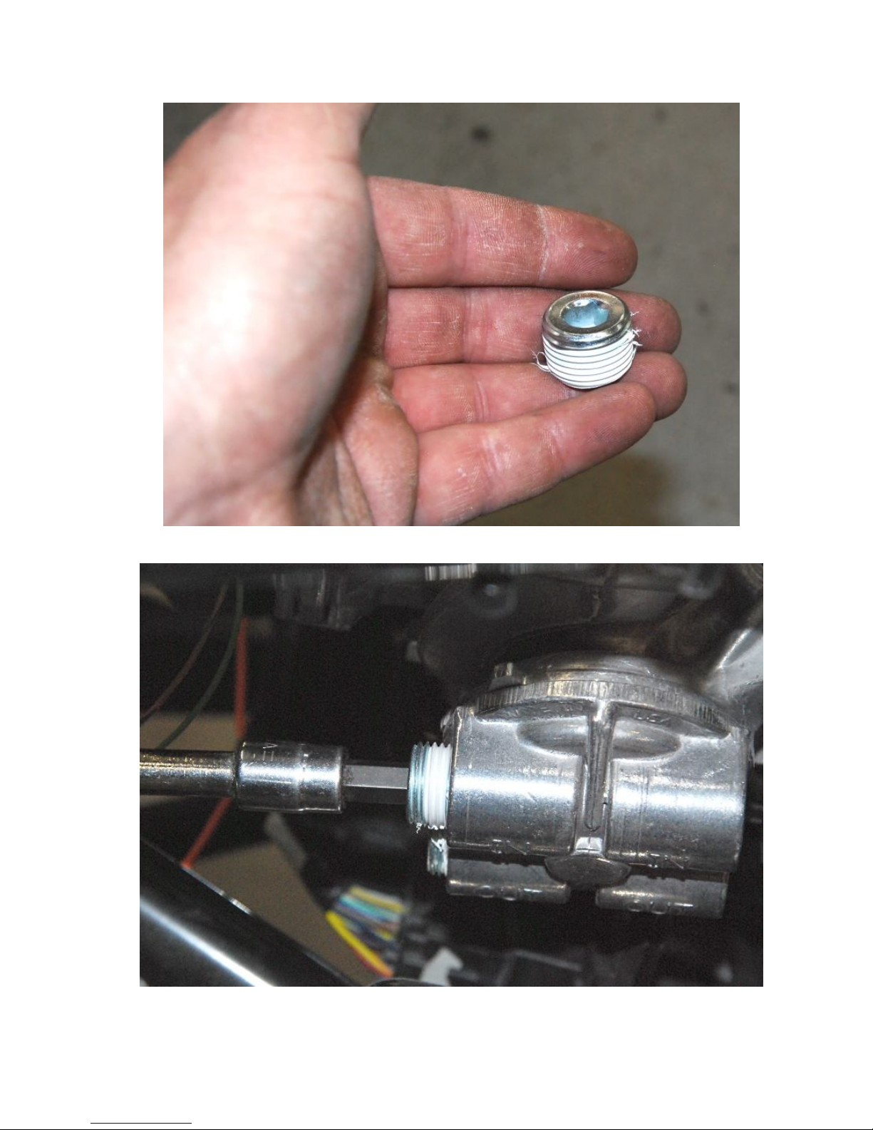
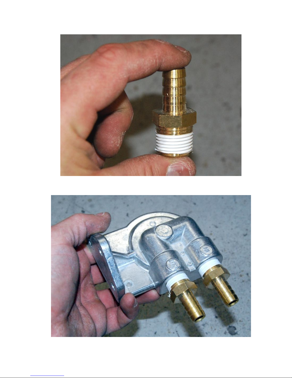
Fuel System.............................................................................................................................................................................23
Cooling system........................................................................................................................................................................27
Vacuum ports and PCV vent....................................................................................................................................................34
Tough emissions..................................................................................................................................................................35
Relaxed Emissions...............................................................................................................................................................38
Steering shaft ..........................................................................................................................................................................42
Wiring.....................................................................................................................................................................................44
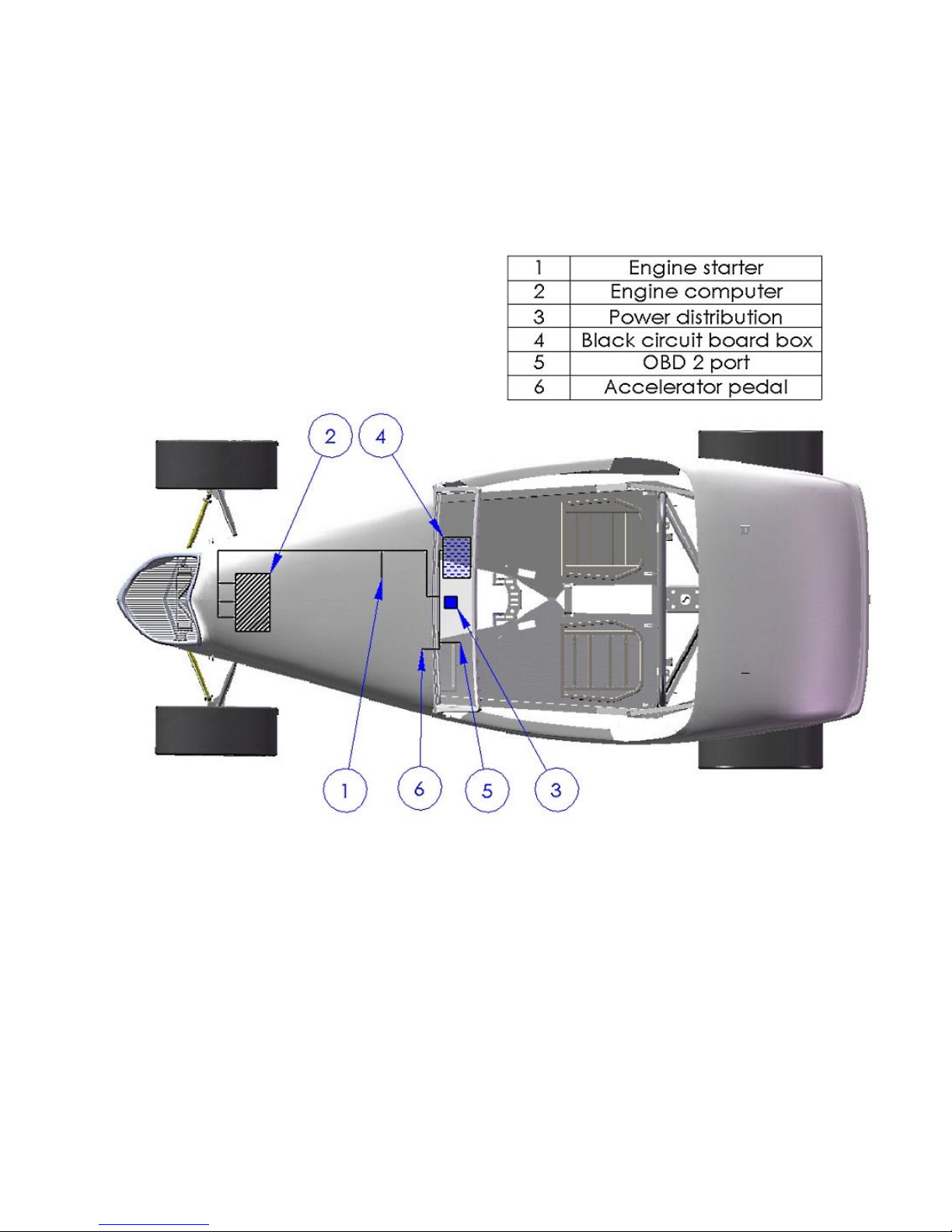
Black circuit board box........................................................................................................................................................45
Fuel Pump ...........................................................................................................................................................................50
Neutral Safety switch...........................................................................................................................................................52
Computer mounting.............................................................................................................................................................54
Starter Solenoid...................................................................................................................................................................59
Radiator Cooling Fan...........................................................................................................................................................64
Power/start...........................................................................................................................................................................67
Gauges.................................................................................................................................................................................70
Tach ................................................................................................................................................................................70
Water Temp Sender .........................................................................................................................................................71
Oil Temp sender ..............................................................................................................................................................73
O2Harness...........................................................................................................................................................................76
Intercooler wire ...................................................................................................................................................................77
Power Distribution...............................................................................................................................................................78
OBD 2 Port..........................................................................................................................................................................78
Alternator................................................................................................................................................................................79
Wiring.................................................................................................................................................................................84
Accelerator Pedal.....................................................................................................................................................................89
Air Intake..............................................................................................................................................................................108
Mass Air Meter..................................................................................................................................................................108
Intake tube.........................................................................................................................................................................113
Exhaust .................................................................................................................................................................................117
Starting the engine ................................................................................................................................................................119
Parts needed
Ford Racing Parts
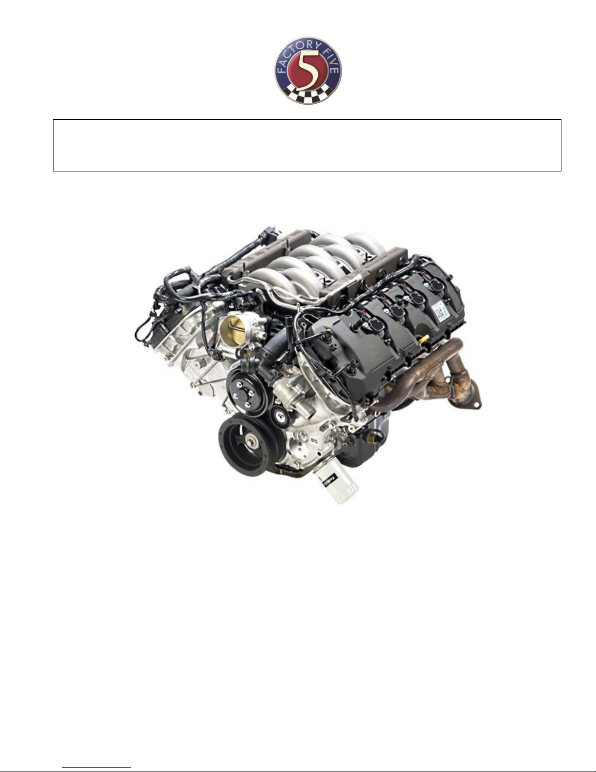
M-6007-M50 - 5.0L Engine
M-6017-A504V – 5.0L engine control pack
M-7003-R58C - TKO transmission
M-7771-A – Bellhousing bolt kit
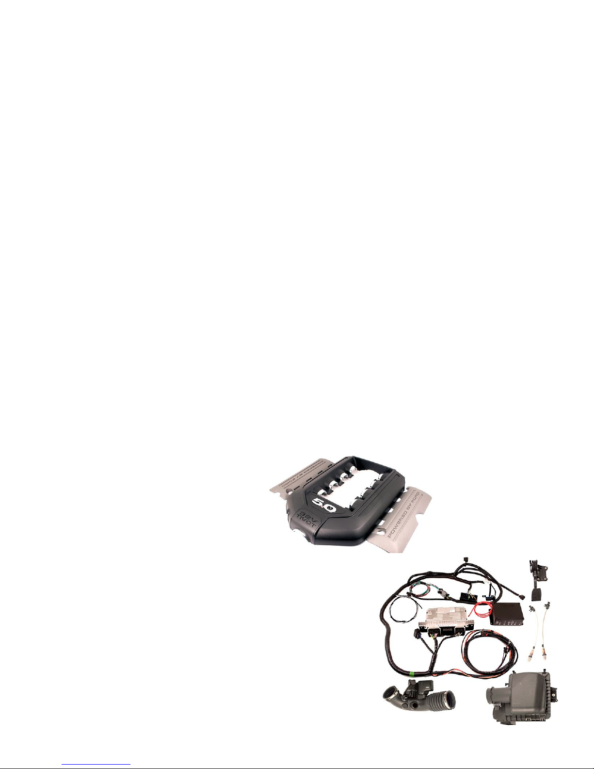
M-9680-M50 – 5.0L engine cover kit
M-7007-A – Transmission Sandwich plate
M-6392-M46 - Bellhousing
M-7560-T46 – Clutch kit
M-7515-A – Clutch fork
M-6375-G46A – Flywheel (If not already on engine)
M-7548-A – Clutch Release Bearing or Ford motor F7ZZ.7548.AA
M-6397-A46 – Clutch bolt kit
M-7600-B – Pilot bearing (If not already on engine)
M-4209ADPT-A - Speed Dial (speedo signal changer)

3
Ford Motor Co. Parts
F3LY-6C070-A – Flywheel access hole plug
BR3Z-8260-B – Mustang upper radiator hose
W500310.S438- Starter bolts (3 needed)
BR3Z-6379-A – Flywheel bolt (8 needed) - If not already on engine
Summit Racing
Fuel System
AEI-13301 – 6AN Fuel pressure regulator
SUM-220166B – 6AN O-ring to straight 6AN Adapter (2 needed)
SUM-220701-B – 6AN to -6AN Hose Barb (1 needed)
FRA-495110-BL – 6AN O-ring to straight -4AN Adapter (1 needed)
SUM-220700-B – 4AN Hose Barb (1 needed)
SUM-220711-B – 90° -6AN to -6AN Hose Barb (1 needed)
SUM-800199 – 0-100 EFI fuel pressure gauge
SUM-G3138 – Fuel Pump
Air Intake System
SPE-9741 – 4” to 3.50” Reducer adapter
SPE-9771 - 4” hose coupling
SPE-9799 - 4” 90 ° intake tube
SPE-9705 - Mass Air Sensor filter adapter
KNN-RU-5149 – 4” ID x 6.50” long Air Filter
Other vendors
Autozone
2005 Ford Mustang GT Starter – DL3299S or similar
If not running A/C, a small 1-wire alternator can be used in the stock compressor location. If A/C is
being used, the following alternator can be used with the brackets described.
2001-03 Honda Civic DX 1.7L MFI SOHC Alternator – 12308
Supplies
Oil – See instructions with engine - 8 quart
Coolant – 2 gallons of concentrate
Oil filter – 92 Ford Mustang, Fram PH8A or similar
Transmission fluid
Teflon tape

4
Information
These instructions assume that the customer has the Hot Rod Coyote Installation kit from Factory Five
Racing
Use the following diagram as a guide for harness locations.
Engine prep
Oil filter relocator
⅜” Hex key, 8mm socket, ratchet, Teflon tape, ratchet extensions, ⅞” wrench, vise grips
Pipe fittings, oil filter relocator
The filter on the engine has a metric thread while the relocator does not.
Do not use the spin-on adapter in the relocator box, it has the wrong thread. Use the loose adapter.
Remove the oil filter that comes on the engine and discard.

5
Put the o-ring in the relocator groove and screw the spin-on adapter onto the block.
Use one of the hose adapters to turn the relocator if necessary so that the spin-on adapter is oriented front to
back.

6
Use Teflon tape on the port plugs.
Screw the plugs into the rear of the spin-on adapter.

7
Use Teflon tape on the hose fittings.
Screw the hose fittings into the front of the spin-on adapter.
Screw hose fittings into the relocator.

8
Screw the threaded nipple into the relocator.
Decide on a location for the relocator. We located it under the steering rack in the center of the frame “X”
so that the filter is accessible from under the car but is high enough to allow clearance. This did require an
extra 90° fitting as shown in the picture.

9
Oil Pressure sender
Pipe fittings, Gauge assembly
H14 Hex key, 12mm deep, 13/16”, 11/16” sockets, ratchet, Teflon tape, ratchet extensions, ⅜”, (2) 9/16”,
11/16”, ⅞” wrenches, vise grips
Remove the stock oil pressure sender from the block located behind the alternator.

10
Use Teflon tape and install the oil pressure gauge sender.
From the gauge box, screw on the ¼” NPT adapter.

11
Put Teflon tape on the adapter then screw on the “T” adapter fitting.
Put Teflon tape on the 1.50” NPT tube.

12
Use vise grip pliers to attach the 1.50” tube to the sender assembly.
Use Teflon tape and install the pipe fitting assembly in the oil pressure location on the engine so that the side
port faces up for now.

13
Use Teflon tape and install the OEM oil pressure sender in the side of the T fitting.
Water Temp Sender
H14 Hex key or socket, 11/16” socket, 12mm deep socket, extension, ratchet, Teflon tape
Water temp gauge sending unit

14
Remove the ¾” NPT plug from the side of the block using a H14 Hex key or socket.
Put Teflon tape on the ¾” NPT to ½” NPT adapter.

15
Screw the adapter into the block using a 1 1/16” socket.
Use Teflon tape on the ⅛” NPT to ¼” NPT adapter included with the gauge.

16
Screw the adapter into the larger adapter on the block.
Put Teflon tape on the sending unit.

17
Use a 12mm deep socket to screw the sender into the adapters.
Engine Bolts
The engine ends up extremely close to the firewall. Cut any extra length off the bolts to prevent damaging
the firewall.

18
Alternator Boss
Hack saw or jig saw
Use a hack saw or sawzall with a course wood blade, a fine metal blade will get gummed up with the
aluminum.
Use a Marker to mark the top stock alternator boss on the driver side as shown. It will hit the frame
otherwise.

19
Cut the boss on the line marked with a jig saw
Transmission Prep
Hack saw or Reciprocating saw, ¾” socket, ratchet
Transmission, Polyurethane engine/transmission mount kit
The two aluminum spacers provides are not used.
If you are using a Tremec 3550, TKO 500 or, a TKO 600 you will need to trim off the unused mounting
boss on the bottom of the case.

20
Trim it flush or just below the pad for the transmission mount.
If not already done, install the flywheel and clutch on the engine.
Remove the vibration damping weight from the clutch fork, it is not needed.
Attach the bellhousing and clutch fork to the engine.
Attach the transmission to the engine.
Table of contents
Other Factory Five Racing Engine manuals
Popular Engine manuals by other brands

Montanari Marco
Montanari Marco evolution 130 Use and maintenance handbook

Clarke
Clarke LC2A Operation and maintenance instruction manual

Hyundai
Hyundai H740E manual

Aerotech
Aerotech BM Series Hardware manual

Mitsubishi
Mitsubishi S16R operating instructions

Kohler
Kohler LOMBARDINI 11 LD 625-3 Use & maintenance