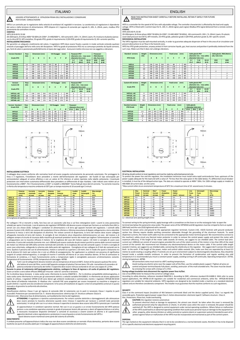
FAE VRTMT 8 User manual

VRTMT
CONTROLLER FOR AC FANS
User’s manual version 03/16
FAE Fa an Applicazioni Elettroniche
www.faefa an.it

This manual can be downloaded from the website: www.faefagan.it in the following languages: English, French,
Spanish, Russian, German. Il presente manuale è scaricabile dal sito : www.faefagan.it nelle seguenti lingue :
inglese, francese, spagnolo, russo, tedesco. e manuel peut être téléchargé sur le site: www.faefagan.it dans les
langues suivantes: anglais, français, espagnol, russe, allemand.
Este manual se puede descargar desde el sitio web: www.faefagan.it en los siguientes idiomas: Inglés, francés,
español, ruso, alemán. Dieses Handbuch kann von der Website heruntergeladen werden www.faefagan.it. Dies
sind die verfügbaren Sprachen: Englisch, Französisch, Spanisch, Russisch, Deutsch. Это руководство можно
загрузить с веб-сайта: www.faefagan.it Доступны следующие языки: на английском, французском,
испанском, русском, немецком.
Instructions for rapid programming 1013
Instructions for language:
1) Turn ON the power supply
2) Press the button , on the keyboard appears the word "LANGUAG " followed by "english".
3) To change the language press . The display shows "english" between two parentheses. At this point press the
arrows until you reach the desired language.
4) Confirm your selection by pressing the button .
5) Return to the status menu by pressing the button .
Loading basic settings:
1) Turn ON the power supply
2) Turn ON the keyboard by pressing simultaneously the key and the key
3) If the display shows "CYCL COOL" you are correctly entered the menu of the working parameters.
4) Click the button until the display shows the message "PIN".
5) Now press the button that will show the four digit pin between two parentheses, indicating the possibility of
change.
6) Click on the button increasing the number of pins up to 0023. Then confirm with the key .
7) Keyboard It now says "BASIC S TTINGS". Confirm again with the key .
8) The screen now shows the word as the title "preset." Confirm with the key .
9) You will see a code consisting of letters and numbers corresponding to the first preset. Scroll through the list by
pressing until he appears in the display the code corresponding to the desired configuration (see user’s manual
on page 20) and confirm with the key . Appears in the display for a few seconds the message "... loaded."
11) Now press until the status menu will appear where "Press.", "Temp" or "Voltage" on the basis of pre-loaded
system. In the event that the wiring has not yet been completed and the machine is not in use, you may receive an
error message that will disappear when the problem is resolved mentioned.
( g.: " RROR lack probe" will disappear when a probe pressure / temperature will be connected to the controller).
Instructions for duty cycle:
1) Turn ON the power supply
2) Turn on the keyboard by pressing simultaneously the key and the key
3) If you see the word "CYCL COOL" you have successfully entered the menu of the working parameters.
4) Press to enter the menu containing the adjustable parameters and press until the parameter you want to
change.
6) Press . The numeric value will be displayed in round brackets (for ex. [20]) , at this point using the arrow or
you can increase or decrease the value to reach the desired one.
7) Confirm the value with the key . Then press the button 2 times to reach the initial screen of the status
menu.

1
INDEX
PR LIMINARY INSP CTIONS - WARRANTY .................................................................................................................... 2
VRTMT – US F ATUR S............................................................................................................................................... 2
Coding........................................................................................................................................................... 3
M CHANICAL INSTALLATION........................................................................................................................................ 4
L CTRICAL INSTALLATION........................................................................................................................................... 5
L D Warning signals ...................................................................................................................................... 6
Panoramic View Cards................................................................................................................................... 6
CONTROL PAN L .......................................................................................................................................................... 9
STAT M NU................................................................................................................................................................ 9
State window boxes ...................................................................................................................................... 9
Language Setting ......................................................................................................................................... 11
OP RATING PARAM T RS M NU - CHILL R................................................................................................................ 11
Parameters Reading and diting.................................................................................................................. 11
Cooling Cycle Parameters [CO1] - CHILL R................................................................................................... 12
Heating Cycle Parameters [H A] - CHILL R................................................................................................... 13
OP RATING PARAM T RS M NU - DRY COOL R ........................................................................................................ 15
Parameters Reading and diting.................................................................................................................. 15
Cooling Cycle Parameters [CO1] – DRY COOL R ........................................................................................... 16
Heating Cycle Parameters [H A] – DRY COOL R.......................................................................................... 17
OP RATING PARAM T RS M NU - SLAV .................................................................................................................. 18
Parameters Reading and diting.................................................................................................................. 18
Working Parameters [IC] – SLAV .............................................................................................................. 19
SP D LIMITS ........................................................................................................................................................... 20
FACTORY PARAM T RS M NU................................................................................................................................... 21
Basic Settings .............................................................................................................................................. 21
Motor Settings ............................................................................................................................................ 23
Relay Settings.............................................................................................................................................. 24
Modbus Settings ......................................................................................................................................... 25
Advanced settings ....................................................................................................................................... 25
Diagnosis..................................................................................................................................................... 26
CLOCK ........................................................................................................................................................................ 27
FAE - Via Alessandro Manzoni, 1036050 Quinto Vicentino - Vicenza – Italy www.faefagan.it

2
!
CAUTION! B FOR INSTALLING TH VRTMT CONTROLL R R AD CAR FULLY TH MANUAL AND
FOLLOW ALL TH INSTRUCTIONS H R IN. WITH POW R D CONTROLL R DO NOT TOUCH TH
INN R L CTRICAL PARTS IN ANY CAS . IN COMPLIANC WITH TH U RUL S AND TH MC
DIR CTIV S, PL AS R MIND THAT TH VRTMT CONTROLL R IS D SIGN D TO B INCORPORAT D
ON MACHIN S OR INT GRAT D ON CONTROL PAN LS AND TH R FOR IS TO B CONSID R D AS A
COMPON NT FOR PROF SSIONAL US . TH MACHIN INSTALLATOR SHALL PROVID FOR TH GUARANT OF
COMPLIANC OF ITS QUIPM NT TO SUCH RUL S. IN TH V NT THAT TH CONTROLL R FAILS TO OP RAT AND
CAUS S DAMAG S TO THINGS OR P RSONS IT SHALL B TH INSTALL R’S R SPONSIBILITY TO PROVID SAF TY
D VIC S OR SYST MS TO PROT CT OR WARN ABOUT TH FAIL D OP RATION. IN ANY MOM NT AND WITHOUT
NOTIC FA FAGAN APPLICAZIONI L TTRONICH R S RV S TO CARRY OUT T CHNICAL CHANG S AIM D AT
NHANCING TH QUALITY OR TH P RFORMANC OF ITS PRODUCTS.
PRELIMINARY INSPE TIONS - WARRANTY
Before installing the controller, make sure that it has not been damaged during the carrying and that it corresponds
to the model ordered. Check that the technical specifications listed in the label match with those written in the
delivery note and in the order form. The controller is covered by a 12-month warranty starting from the delivery. The
warranty covers production defects not due to damaging or wrong use, for goods returned to us X-WORKS. Any
damage occurred during the carrying shall be reported to the carrier in with the local legislation.
DISPOSAL
The sign marked on the equipment indicates that it is not to be considered as a normal domestic waste, therefore it
has to be disposed of in a specific electrical and electronic equipment recycling point.
SERIAL NUMBER _________ /_______
SOFTWARE VERS. ________
VRTMT – USE FEATURES
The VRTMT electronic controller is normally used to control the speed of AC fans, pumps and centrifugal pumps. It is
based on the principle of symmetrical phase partialisation and It is suitable for adjustable voltage motors. VRTMT
operates on the basis of the inputs received through the measurements, the parameters settings values, the
controlling I/O and the control panel. The control panel is used to set the parameters values and read the
information about the unit status. VRTMT is provided with Modbus connection to dialog with a supervising remote
device.

3
ODING
Position 1 2 3 4 5 6 7
VRMT 12 PT PL 55 XX (coding example)
Pos. 1 : Adjuster model
Pos. 2 : Nominal current 8 = 8A, 12 = 12A, 20 = 20A...
Pos. 3 : Power supply C= 230/400V∼ 50/60Hz
D= 440/460V∼ 50/60Hz (not for VRTMT8)
Pos. 4 : Type of probe/s PT = pressure and temperature
Pos. 5 : Container PL = plastic
Pos. 6 : Protection grade 55 = IP55
Pos. 7 : Variants/additions O = weekly clock, C = operable door , D = Oled dispaly
The data are related to operate at 400V~ 50Hz.
For 230V voltage supply or VRTMTXXD
odels at 440-460V all current are the sa e.
*Max current refers to an enviro ent
te perature of 50°C for a axi u ti e of 10
second every 5 inutes.
TE HNI AL HARA TERISTI S
POW R SUPPLY 230/400V~ +10%/-15%, (440/460V~ on demand)
FR QU NCY 50-60Hz
MAX VOLTAG POW R OUT >97% of power supply
OP RATING T MP. -25°C/+50°C (-25°C with Oled display, -20°C with lcd display)
STORING T MP. -40°C/+80°C
MAX T MP.DISSIPATOR 75°C
PROT CTION GRAD IP55 self extinguishing plastic box (ball pressure test 85°C),pollution grade 3
L CTRIC CLASSIFICATION Class II at the command imputs (insulation of 4kV between commands block and the
device supplied parts). Class I as regards the accessible parts.
PROT CTIONS Phase lost, inside overheating, sensor missing, external emergency (motor klixon)
WARNING : the regulator restores automatical.
Protection against power surges Class II
ACTION-DISCONN CTION Type 1(Y). Residual current motor < 15mA
SOFTWAR STRUCTUR Class A
L CTRICAL CONN CTION Class Y
According to safety directive, reference standard N60730-1. According to electromagnetic directive, reference
standard N 61800-3. With refer to some typical applications, the VRTMT8-12-20 regulators are suitable for
residential and commercial ambients, while the VRTMT28-40-50-60 regulators are suitable for industrial ambients.
VRTMS regulators are designed to be installed inside a machine or a standard electrical cabinet and are therefore
considered a component. The installer must guarantee that the machine conforms to such regulations.
Power
max
(kVA)
urrent
nominal
(A)
urrent
max*
(A)
Power
dissipation
(W)
VRTMT 8 5,5 8 12 30
VRTMT12 8 12 23 60
VRTMT20 13 20 30 80
VRTMT28 19 28 50 120
VRTMT40 26 40 70 155
VRTMT
50
32 50 70 180
VRTMT
60
41 60 80 250
!

4
ME HANI AL INSTALLATION
The VRTM regulator must be wall-mounted vertically, in order to guarantee adequate dispersion of heat in the area
of air circulation and prevent obstructions to air flow in the dissipator zone.
VRTMT has IP55 grade protection, anyway protect it from corrosive liquids, gas, heat sources and position it
preferably sheltered from the sun's rays. Make sure that it does not undergo vibrations.
able glands IP68 (Metric) Model Weight
(kG)
Dimensions (mm)
A B *
Fixed screw (mm)
D E F Ø M16 M20
M25
M32
M40
VRTMT 8 2,5 230 165 150 215
80 / M4 1+(1)
- 2
-
-
VRTMT12 4 230 265 165 215
170
/ M4 1+(1)
1
2
-
-
VRTMT20 4,8 230 265 230 215
170
/ M4 1+(1)
1
2
-
-
VRTMT28 7 340 270 235 322
165
/ M5 1+(1)
1
-
2
-
VRTMT40 9 340 270 235 322
165
/ M5 1+(1)
1
-
-
2
VRTMT50 17 340 440 235 322
340
170
M5
1+(1)
1
-
-
2
VRTMT60 18 340 440 235 322
340
170
M5
1+(1)
1
-
-
2
C* = increase C value of 29mm with polycarbonate operable door.
(1) = hole closed with watertight plug.

5
ELE TRI AL INSTALLATION
Loosen the screws and remove the cover completely before performing wiring. Connect the power wires and ground
to the appropriate regulator terminals. Custom (+S ) Controls with ground conductor section less 10mmq require
double earthing connection obtainable through the grounding of the aluminum heatsink. To avoid dispersion
currents, the motor earth cable must be connected to the appropriate motor terminal ground. We recommend to
connect to the machine’s safety circuit any thermal motor protector in order to remove the control power supply
and protect the motor with maximum efficiency. The thermal motor protector may be otherwise connected directly
to the I4 control card’s terminal. If the length of the motor cable exceeds 10 metres, we suggest to use shielded
cable. The control load (min. current out >200mA) can consist of several engines provided the sum of the rated
currents of the motors is less than 20% of the rated current of the control. We recommend not introduce any
electromechanical device on the motor cable. If the control cable length exceeds 3 metres, we suggest to use
shielded cable, connecting the shield only on the regulator. We suggest don’t connect the control 0volt to the earth.
If the length of the power, motor and control cables exceeds 10m, make sure they are separated by at least 0.3
metres to avoid creating a coupling effect.
If controls are set up in environment subject to electromagnetic disturbance, they should be housed inside a suitable
metallic enclosure. In order to prevent the formation of condensation and regular working also cold temperature it is
recommended you insure a constant power supply, avoiding turning it off continually.
All connections wires must resist to a 80°C working temperature.
Avoid routing any electric wires near the copper coils of the filter, use the suitable plastic
support ! Tighten all wires on control and power terminal boards fully down, avoiding
protrusion of the multi-stranded wire.
Do NOT touch the electronic equipment when the power line is on !
During voltage insulation tests disconnect the regulator power lines In/Out.
Use a true RMS tester to measure the current or voltage values.
The cover must be closed by screwing the screws with a torque of 1.2 Nm.
In the event that regulator operation failure could cause damage to objects or physical
injury, it is the responsability of the installer to add devises or systems that protect against,
or warn of, control failure.
Check the position of the voltage change jumper according to the
supply voltage available, to the type of control (see coding
paragraph page 3, pos.3) and to the panoramic view of the
corresponding card.
To protect the power line and the regulator, the installation technician
must install extra-rapid semiconductor fuses upstream of the power
supply adequate for the load and with a value of I ² t less than the value
given in the table below. If a differential circuit breaker is installed, it must be of the delayed action type. The
regulators with rated current > 16A are in accordance to the I C61000-3-12 on condition that the short circuit ratio
Rsce is greater than or equal to 120 at the interface between the user power supply and the public network. For
values Rsce minor can reduce harmonics by increasing the voltage/minimum speed.
Power Supply
(230/400V) 230 400
D (440/460V) 440 460

6
VRTMT8
…12 … 20
… 28
… 40 … 50 … 60
2,5 2,5/4
6 10
Section power cables (mm²) 1,5
(Ls = 9) (Ls =12) (Ls = 15)
16 16/25
Section control cables (mm²) 0,2÷1,5 (Ls = 9)
Line fuses (A) 10/16 16/20
25 35 50 63 80
Extrarapid fuses (A) 16 25 32 50 63 80 100
I²t (A²S) max energy c.c. 610 720 720 8000 15000 15000
80000
Ls = electrical wire peeling length (mm)
To connect wiring to the spring terminals, apply leverage with a screwdriver on the lever or on the rectangular hole
to open the terminal (see below the panoramic view cards). The power wires of the VRTMS50 and 60 regulators
must be crimped to form an eyelet (M6 hole) and the nuts ( 10) tightened with a wrench.
LED WARNING SIGNALS
DL1 : yellow, starts to flash with input signal at
minimum and increases the flashing frequency as
the signal rises. It goes on steady with signal =
100%. It follows the priority signal (see Basic Sett.
[BS] in the Factory Parameters menu).
DL2 : green, steady ON = power supply ON.
DL3 : red, warning alarm ON:
1 flash = power phase lost.
2 flashes = external emergency.
3 flashes = internal over-temperature.
4 flashes = probe missing.
5 flashes = stop for parameters programming or
error settings.
DL4 : green, flashing in modbus transmission.
DL5 : red, flashing in modbus reception.
PANORAMI VIEW ARDS

7

8
ONTROLS TERMINAL BOARD
Term.
Description Application Page
T1+ Serial RS485, Modbus RTU - Slave
T1 - Serial RS485, Modbus RTU - Slave
Serial connection line to a Master controlled device
25
0V Ground I/O Mass I/O
IF
IF
Pwm FV, 2..20kHz input (Ri =500Ω, 5..24V)) Variable frequency command for mode slave
running
22
I 4 xternal emergency input Open immediately blocks the control. It can be
connected to the load temp. protecting device/s
I 3 Start/Stop input Programmable Start/Stop input 23
I 2 Limit Speed function input Closed modifies the adjusting modes. It is often
used for the night silenced operating
20
I 1 Direct/Reverse function input Open enables the Cool1 cooling mode. Closed
enables the Heat or Cool2 heating mode (to be set
on basic sett. menu)
22
0V Ground I/O Mass for the digital inputs
0.10 Analog input , type 0.10V (Ri = 40k Ω) 0..10V command for mode slave running 22
+V 12V power supply output = (max 30mA) 4..20mA pressure transducer power supply
N Relay 1 closed norm. contact output
OM Relay 1 common contact output
(1A-250V~/3A-30V=)
NO Relay 1 open norm. contact output
Programmable output. With standard setting for
Defect, the relay is enabled (NO-COM eachother
closed) and is disabled by turning to the position
represented in the picture in emergency case.
24
+5V 5V power supply output = (max 15mA) Ratiometric press. transd. and NTC power supply
IN 1 Analogical input 1, type 0,5…4,5V / ntc
(10 kΩ @25°C, β3435), (Ri = 10 kΩ) / pwm 5..15V
Ratiometric pressure transducers / NTC sensor /
Pwm 100Hz type with variable average value
21-22
0V Ground I/O Mass for analogical input
4.20 Analogical input 1, type 4…20mA (Ri = 100 Ω) 4..20mA pressure transducers input,command for
mode slave running
21-21

9
ONTROL PANEL
The control panel visualizes in real time the inputs and outputs of the adjuster and allows to set the parameters. It
is provided with a back-illuminated LCD/OL D display and with four keys described below.
STATE MENU
After the device is powered the display visualizes the firmware versions of the adjuster and the keyboard. Then, if
no error occurs, appears the first state window which visualizes the temperature or the pressure registered by
input 1:
RUN in operating state
FLT in block state
RDY if in Stop state
The cycle used for the adjusting is visualized at the right bottom: CO (COOL) or H A (H AT) followed by the
number 1 or 2 for first or second cycle.
In this mode:
•Press the key to slide the state menu downward;
•Press the key to slide the state menu upward.
STATE WINDOW BOXES
Defines the output voltage/speed. The percentage value refers from 0 to 98% of power
voltage.
INPUT 1 : Defines the percentage of the IN1 input among the following possible
signals: 0..10V=, 4..20mA, pwm (100Hz type with variable average value).
Goes to the next
visualization / decreases a
parameter
Goes to the previous
visualization /
increases a parameter
nters the menu and the
parameters / confirms the
variation of a parameter
parametro
scapes from the menu and
the parameters / cancels a
variation of parameter
OUTPUT
67
%
DRY COOL R
Temp.1
21.3 °C
[CO1]
[RUN]
HILLER
Press.1
20.3 bar
[CO1]
[RUN]
23
INPUT
%
SLAV

10
INPUT PWM : Defines the percentage of the control value detected in the input
dedicated to the PWM input signal with variable frecuency (available only on
demand).
The percentage value refers to the range defined in the basic settings, in the PWM
min and PWM max parameters.
INPUT MODBUS : Defines the value transmitted by the modbus RTU to an external
MAST R controller. The value is effective if included inside the range limited by the
parameters Min limit and Max limit of the motor settings [IM].
Defines the operating mode of the adjuster:
Chiller , Dry Cooler, Slave.
This is a display-only parameter. To edit it go to the basic settings menu inside the
“PR IMPO [IB]” menu.
Defines the state of the digital inputs of the terminals I1, I2, I3, I4.
An asterisk will be displayed next to the digital terminals connected to the terminal
“0V”.
Attention: In Slave mode the digital commands I1, I2, I3, I4 are not active.
Defines the state of the relay 1, relay 2 and relay 3. The asterisk means that they are
powered and the contacts NO and COM are eachother closed. The instructions 2 and
3 are displayed only with [S1 CARD OPTION].
[S1 CARD OPTION] Displays the temperature of the ambient temperature sensor
connected to S1 card, expressed in degrees centigrade. If the card S1 is installed and
the probe is not connected, will show " sensor miss".
Defines the software version of the adjuster.
[WIT CLOCK OPTION]
Displays the date and time of the variable weekly clock.
This is a display-only window box.
To set the clock go to the clock menu inside the “operating parameters”.
aution: in the event of warning alarm the state window box disappears and an alarm box is displayed until the
problem is solved.
Alarm warning example:
Warns about an alarm due to the control I4 open.
Other warnings refer to the alarms of: overheating and probe missing
MOD
“chiller”
*
INPUT
-
1
-
2
-
3*
-
4
OUTPUT
-
1
-
2
-
3*
V RSION
1.00
W D
13:27:13
05.09.2012
RROR!
external
*
23.2
XT. T MP.
°C

11
LANGUAGE SETTING
From any screen of the operating menu press the key to visualize the language set.
To change the language press and move with the arrows until it reaches the
language to set among the following available languages: English – Italian – German –
French – Spanish – Russian [available only with OLED display].
Press again the key to save the setting.
The asterisk at the right bottom indicates the language set.
Press to return to the sate menu.
OPERATING PARAMETERS MENU - HILLER
The operating parameters menu can be accessed from any visualization of the state menu, by pressing together
the keys + (hold the key pressed and press the key ).
The menu windows include the menu name and the corresponding [identifying
code].
The second line of the display is dotted.
•Press the key to access the parameters of the visualized menu;
•Press the key to return to the state menu;
•Press the key to go to the next menu;
•Press the key to return to the previous menu.
PARAMETERS READING AND EDITING
The parameters windows display the name of the parameter, the [identifying code]
of the corresponding menu, the value of the parameter and the unit of measure.
• to go to the parameter below;
• to go to the parameter above.
To change the value of the parameter press , the arrow and the value of the
parameter in brackets mean that the system is in the parameter editing mode, edit
the value by pressing the following key:
• to increase the value
• to decrease the value
• to save.
• to return to the parameter;
-
>( nglish)
*
LANG.
LANG.
nglish
*
HILLER
[
IC
]
-----------------------
COOL 1 S T.
HILLER
13.0
P1
[IC]
bar
HILLER
-
>(13.0)
P1
[IC]
bar

12
OOLING Y LE PARAMETERS [ O1] - HILLER
(example of parameterization with basic setting "mp420_50", see page 20)
Pressure of the voltage/speed V1 point.
Min. 0 bar Max. P2 Def. 20 bar
Pressure of the voltage/speed V2 point.
Min. P1 Max. P_MAX Def. 24 bar
Maximum production pressure, above this the output is at the voltage
MotorMaxLim.
Min. P2 Max. Full Scale Def. 25 bar
Voltage/speed of the pressure point P1.
Min. MotorMinLim Max. V2 Def. 20%
Voltage/speed of the pressure point P2.
Min. V1 Max. MotorMaxLim Def. 90%
HILLER
HILLER
HILLER
20.0
P1
[IC]
bar
HILLER
24.0
P2
[IC]
bar
HILLER
20
V1
[IC]
%
HILLER
25.0
P_MAX
[IC]
bar
HILLER
90
V2
[IC]
%

13
HEATING Y LE PARAMETERS [HEA] - HILLER
(example of parameterization with basic setting "mp420_50", see page 20)
aution: The heating cycle can be replaced by a second cooling cycle [CO2] by changing the setting of the
parameter Second Mode (page 22).
Pressure of the voltage/speed V2 point.
Min. P_MAX Max. P2 Def. 7 bar
Pressure of the voltage/speed V1 point.
Min. P1 Max. Full Scale Def. 11 bar
Maximum production pressure, below this the output is at the voltage
MotorMaxLim.
Min. 0 bar Max. P1 Def. 5 bar
Voltage/speed of the pressure point P2.
Min. MotorMinLim Max. V2 Def. 20%
Voltage/speed of the pressure point P1.
Min. V1 Max. MotorMaxLim Def. 90%
HILLER
HILLER
11.0
P2
[IH]
bar
HILLER
20
V1
[IH]
%
HILLER
5.0
P_MAX
[IH]
bar
HILLER
90
V2
[IH]
%
HILLER
7.0
P1
[IH]
bar

14

15
OPERATING PARAMETERS MENU - DRY OOLER
The operating parameters menus can be accessed from any visualization of the state menu, by pressing together
the keys + (hold the key pressed and press the key ).
The menu windows include the menu name and the corresponding [identifying
code].
The second line of the display is dotted.
•Press the key to enter the parameters of the visualized menu;
•Press the key to return to the state menu;
•Press the key to go to the next menu;
•Press the key to return to the previous menu.
PARAMETERS READING AND EDITING
The parameters windows display the name of the parameter, the [identifying code]
of the corresponding menu, the value of the parameter and the unit of measure.
• to go to the parameter below;
• to go to the parameter above.
To change the value of the parameter press , the arrow and the value of the
parameter in brackets mean that the system is in the parameter editing mode, edit
the value by pressing the following key:
• to increase the value
• to decrease the value
• to save.
• to return to the parameter;
DRY COOL R
COOL 1 S T.
-----------------------
[C1S]
DRY COOL R
T1
12.0
°C
[IC]
DRY COOL R
T1
-
>(12.0)
°C
[IC]

16
OOLING Y LE PARAMETERS [ O1] – DRY OOLER
(example of parameterization with basic setting "mtNTC_L", see page 20)
Temperature of the voltage/V1 speed point.
Min. 0 °C Max. T2 Def. 22,0 °C
Temperature of the voltage/V2 speed point.
Min. T1 Max. T_MAX Def. 28,0 °C
Maximum production temperature, above this the output is at the voltage
MotorMaxLim.
Min. T2 Max. 95 °C Def. 29,0 °C
Voltage/speed of the temperature point T1.
Min. MotorMinLim Max. V2 Def. 20%
Voltage/speed of the temperature point T2.
Min. V1 Max. MotorMaxLim Def. 90%
HILLER
HILLER
DRY COOL R
T1
22.0
°C
[IC]
DRY COOL R
T2
28.0
°C
[IC]
DRY COOL R
T_MAX
29.0
°C
[IC]
DRY COOL R
V1
20
%
[IC]
DRY COOL R
V2
90
%
[IC]

17
HEATING Y LE PARAMETERS [HEA] – DRY OOLER
(example of parameterization with basic setting "mtNTC_L", see page 20)
aution: The heating cycle can be replaced by a second cooling cycle [CO2] by changing the setting of the
parameter Second Mode (pag.22).
Temperature of the voltage/V2 speed point.
Min. T_MAX Max. T2 Def. 22,0 °C
Temperature of the voltage/V1 speed point.
Min. T1 Max. 95 °C Def. 24,0 °C
Maximum production temperature, over this the output is at the voltage
MotorMaxLim.
Min. 0 °C Max. T1 Def. 21,0 °C
Voltage/speed of the temperature point T2.
Min. MotorMinLim Max. V2 Def. 20%
Voltage/speed of the temperature point T1.
Min. V1 Max. MotorMaxLim Def. 90%
HILLER
HILLER
DRY COOL R
T1
22.0
°C
[IH]
DRY COOL R
T2
24.0
°C
[IH]
DRY COOL R
T_MAX
21.0
°C
[IH]
DRY COOL R
V1
20
%
[IH]
DRY COOL R
V2
90
%
[IH]

18
OPERATING PARAMETERS MENU - SLAVE
The operating parameters menus can be accessed from any visualization of the state menu, by pressing together
the keys + (hold the key pressed and press the key ).
The menu windows include the menu name and the corresponding [identifying
code].
The second line of the display is dotted.
•Press the key to enter the parameters of the visualized menu;
•Press the key to return to the state menu;
•Press the key to go to the next menu;
•Press the key to return to the previous menu.
PARAMETERS READING AND EDITING
The parameters windows display the name of the parameter, the [identifying code]
of the corresponding menu, the value of the parameter and the unit of measure.
• to go to the parameter below;
• to go to the parameter above.
To change the value of the parameter press , the arrow and the value of the
parameter in brackets mean that the system is in the parameter editing mode, edit
the value by pressing the following key :
• to increase the value
• to decrease the value
• to save.
• to return to the parameter;
-----------------------
[I
C
]
SLAV
IMPO.SLAV
20
V1
[
IC]
%
SLAV
-
>20
V1
[
IC
]
%
SLAV
This manual suits for next models
6
Table of contents
Other FAE Controllers manuals