®
6
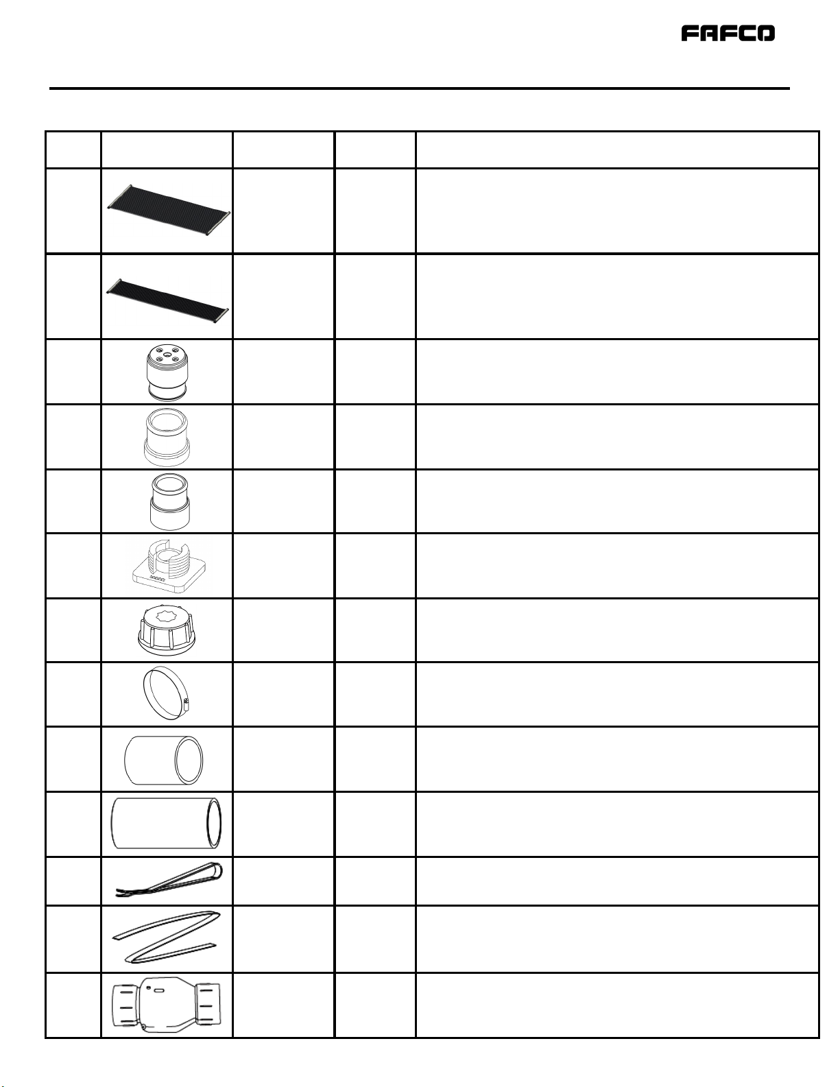
Item Image Name P/N Description
1
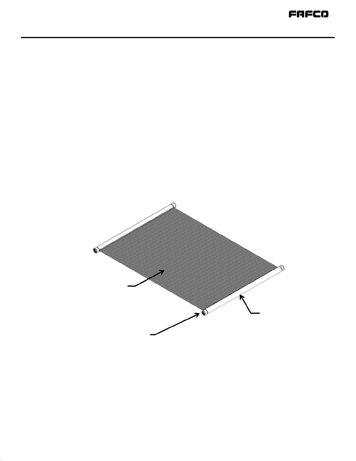
SunSaver®
(4ft x 12 ft)
(4ft x 10 ft)
(4ft x 8 ft)
822 (12ft)
820 (10ft)
818 (8ft)
4ft SunSaver®Collectors. These 4ft wide Collectors are available in three
different lengths, 12ft (48 sq.ft.), 10ft (40 sq.ft.) and 8ft (32 sq.ft.)
2
SunSaver®
(2ft x 12 ft)
(2ft x 10 ft)
(2ft x 8 ft)
09523 (12ft)
09524 (10ft)
09525 (8ft)
2ft SunSaver®Collectors. These 2ft wide Collectors are available in three
different lengths, 12ft (24 sq.ft.), 10ft (20 sq.ft.) and 8ft (16 sq.ft.)
3
Vacuum Relief
Valve (VRV) 188
Black, weather resistant CPVC, 2” PVC pipe size, barbed. Seals system
when pressurized and allows collectors to drain when the system is off.
Adapts to Solar Collector using Short Rubber Coupler.
4
End Cap 05380
Black, weather resistant CPVC, 2˝PVC pipe size, barbed. Adapts to solar
collector using Short Rubber Coupler.
5
Pipe Adapter 05381
Black, weather resistant CPVC, 2” PVC pipe size, barbed female slip.
Used with a Rubber Coupler to adapt the VRV to PVC.
6
Base 06918
Black, weather resistant polymer. Mounts solar collector header and
body straps to a roof or rack using a 1/4˝lag bolt and cap.
7
Cap 06919
Black, weather resistant polymer. Threads onto base to secure strap.
8
21/2” Hose
Clamp 02031
Stainless steel 21/2” hose clamp. Secures Rubber Couplers to barbed
fittings. Tighten using flat head or 5/16” socket driver.
9
Rubber Coupler
(3-1/2”) 02033
31/2” long, 23/8” inner diameter reinforced EPDM used to join the barbed
fittings on a VRV with those on the Pipe Adapter.
10
Rubber Coupler
(5”) 02035
5˝long X 2-3/8˝inner diameter reinforced EPDM used to join the
collectors to the barbed pipe adapters. Allows for flexibility between
collectors and hard piping.
11 Header Strap
(32”) 03431 Black, weather resistant braided polyester. Anchors top solar collector
header to cap and base.
12
Body Strap 03430
Black, weather resistant braided polyester. Anchors solar collector body
to cap and base. (150ft Roll)
13
Check Valve 02046
White, PVC 2˝female slip check valve prevents water from flowing
backward through the filter and backflushing debris into the pool when
the collectors drain.
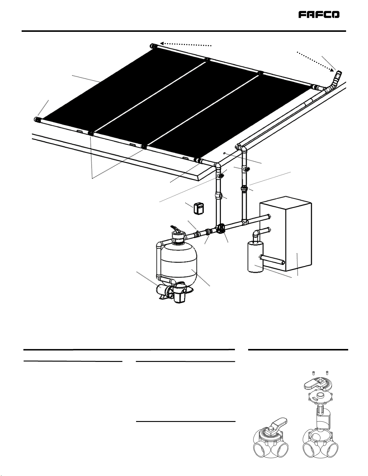
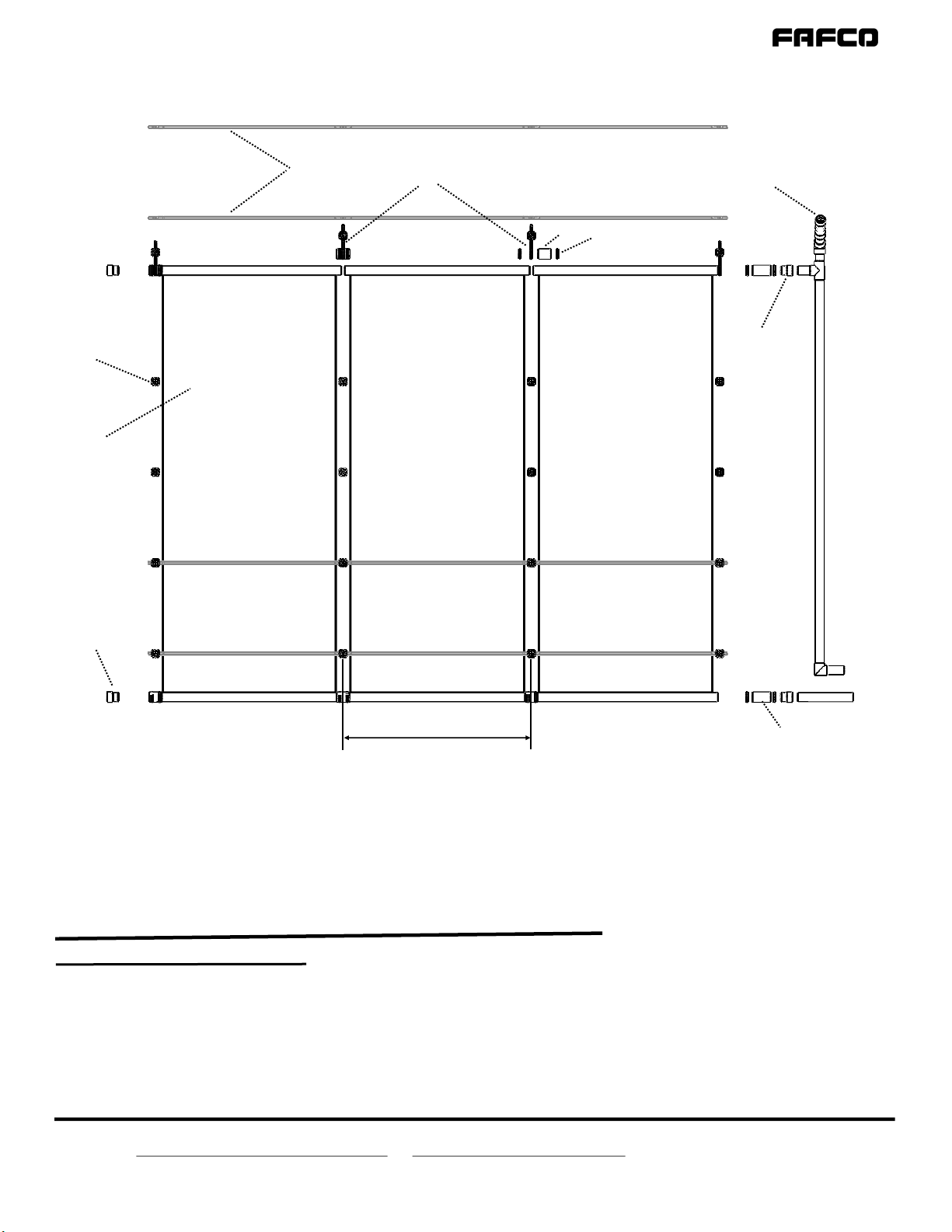
Array Components
Components & Parts List