Electroconcept CLUBSCAN 120 User manual

SCAN 120
LED SCANNER
CLUBSCAN 120
Instruction manual
Thank you for urchasing this roduct.
Please carefully read this manual before using this scanner
Responsibility :

On no account the Electroconcept company shall be held responsible for any damages of any nature
whatsoever, notably the operating loss, destruction of consumables (tape, disc, CD) or any other
financial loss resulting from the use or the impossibility to use your equipment. n addition
Electroconcept shall not be held responsible for damages due to an improper use of this product.
Warranty :
Electroconcept products have a 2 years manufacturer warranty. The equipment shall be returned
prepaid (at the customer's own expense). Any freight collect will be refused. The equipment shall be
returned in its original packaging. The equipment's restitution will be at our own expense.
Are excluded from warranty: damages due to fault, negligence, lack of maintenance by the user
(broken, burnt, heated, wet, sandy...etc devices), already installed devices of which the failure would
originate from an improper installation or use by the customer.
This manual is an integral art of this roduct, you will need to kee it during all of
your roduct shelf-life. In the event of cession of your roduct to a third arty, you
must also give this manual to this third arty.
TABLE OF CONTENTS
1. Safety instructions
2. Technical specifications
3. Scanner starting up
1. Access to main functions
2. DMX wiring
4. DMX control channels and values
5. Troubleshooting
6. Cleaning
2

1. Safety instructions
Please carefully read these instructions as they include
valuable information for installation, o eration and
maintenance of this device.
Warning
Keep this manual for future consultations. f you resell your scanner to an other individual,
make sure to also give him this manual.
Unpack and carefully check that the scanner didn’t take any damages during the transport
before using it.
Before any connection, make sure that both the voltage and the frequency of your power
source match your scanner specifications.
Check your device as well as your equipment’s grounding.
This device is only meant for indoor use ; protect it from heat and humidity (allowed
ambient temperature from 10 to 40°C).
The scanner must be set up in a ventilated area, at least 50cm away from any adjacent
surface. Check that no ventilation hole is blocked.
Unplug the scanner’s power source before any maintenance or handling operation.
Only replace the fuse by a fuse of the same type.
n order to avoid any fire hazard, check for any flammable source nearby.
Use safety cables to secure the scanner. Take into account the weight of the scanner upon
positioning it on a high up structure in order to avoid the fall of the structure and thus
risks of injury.
Switch off the power and let the scanner cool down for about 15 minutes before transport,
for the scanner’s surface may be hot still.
n the event of a serious functioning problem, stop immediately to use the device. Do no
ever try to repair the device by yourself. Repairs made by unqualified individuals may
cause damages or malfunctions. Contact the nearest approved technical support center.
Always use spare parts of the same type.
Do no connect the scanner to any dimmer or power pack.
Do no open the device during its operation, the high voltage may cause a lethal electrical
shock.
n order to prevent or reduce risks of electrical shock or fire, do not expose the device to
rain or humidity.
Do not ever touch the led with your bare fingers after use to avoid serious injuries, for the
led may be very hot still.
Do not start the scanner without led to avoid degradation of the box..
3

Re lace the box and the lenses if they are visually damaged (for exam le cracks or
dee cuts during trans ort or handling). This is essential.
Do not look straight at the light going out of led when the scanner is switched on.
n order to prevent any risks of electrical shock you must not remove the cover. There
is no useful part for the user inside. Refer the repair to qualified personnel.
Installation
The scanner must be attached via its screw holes to the support with help of the provided
hook. Always make sure the scanner is firmly attached to avoid vibrations and sliding during
the operation.. Always make sure the structure to which the scanner is attached is secured and
able to bear 10 times the scanner’s weight.
2. Technical s ecifications.
This device does not roduce radio interference. This device meets Euro ean and
French requirements. Com liance has been established, and statements and
res ective documents have been registered by the manufacturer. This device has been
made for indoor decorative lighting effects.
Power supply : AC 220-250V 50/60Hz
Power: 150 W
Lamp : LED 120W
Shutter/Dimmer : Blackout, 0~100 variable strobe speed and soft transition
Movement: Pan: 180° / Tilt: 70°
Beam angle: from 12° to14,5°
Functions:
- wheel color 8 colors + white
- gobos wheel 7 fixed gobos + open
- 3 facet rotating prism
- linear focus
Weight/Dimensions :7,2 Kg / 470x190x140 mm
Operating mode
-DMX control 15 or 19 channels/Stand-Alone with built-in microphone/Stand-Alone with
automatic mode /Master/Slave Mode
3.Scanner starting up
3.1. Access to main functions :
Control anel:
”MENU“ “▼ ” “▲” ”ENTER”
Press the “MENU” button to access to functions then « ▼ » or « ▲ » to browse through sub-menus,
« ENTER » to confirm.“MENU” to go back.
4
2 Operating modes are available : DMX control, Stand-Alone mode
MENU DESCR PT ON
Mode DMX
Stand-Alone: Auto 1 /Auto 2 Auto 3 /Auto 4
XY effect 1/ XY effect 2 / XY effect 3 /XY effect 4
random effect / Sound
address DMX DMX address selection 001-512
Channel mode Selection of DMX mode15 or 19 channels
X reverse ON/OFF pan inversion
Y reverse ON/OFF tilt inversion
XY exchange ON/OFF
Screen mode ON backlight on
OFF backlight shuts off after 30 secondes
Version version of firmware /DMX channel/time since activation/number of total hours.
Reset ON/OFF
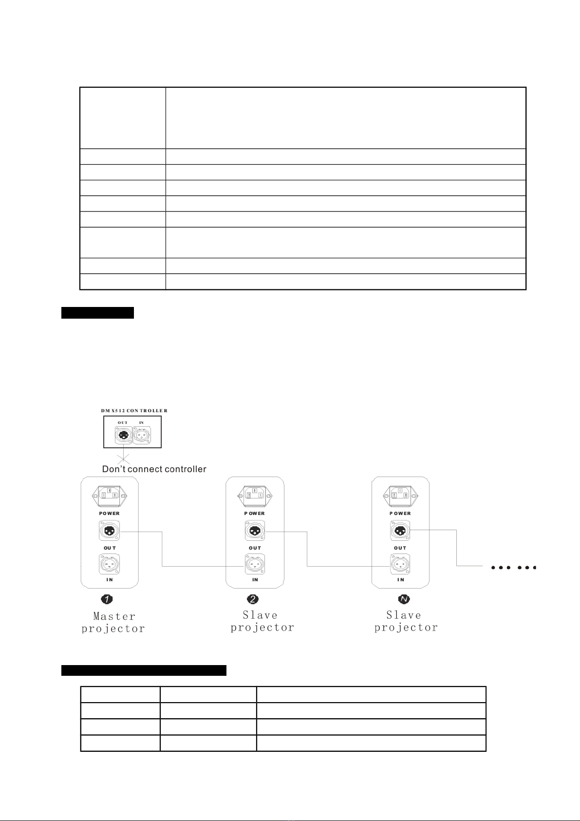
3.2 DMX wiring
This product uses 3-pin XRL connectors for the DMX512 connection:
Pin 1 : Ground , Pin 2 : Data (-), Pin 3 : Data (+).
Example : connection between different fixtures in Master/Slave mode:
NB : in order to reduce signal errors, think of using a plug a the end of your DMX link..
4.DMX Control channels and values115 or 19 channels
CHANNEL VALUE FUNCT ON
1 PAN 0-255 Pan
2 PAN fin 0-255 Pan Fin
3 T LT 0-255 Tilt
5
This manual suits for next models
1
Table of contents
Other Electroconcept Lighting Equipment manuals


