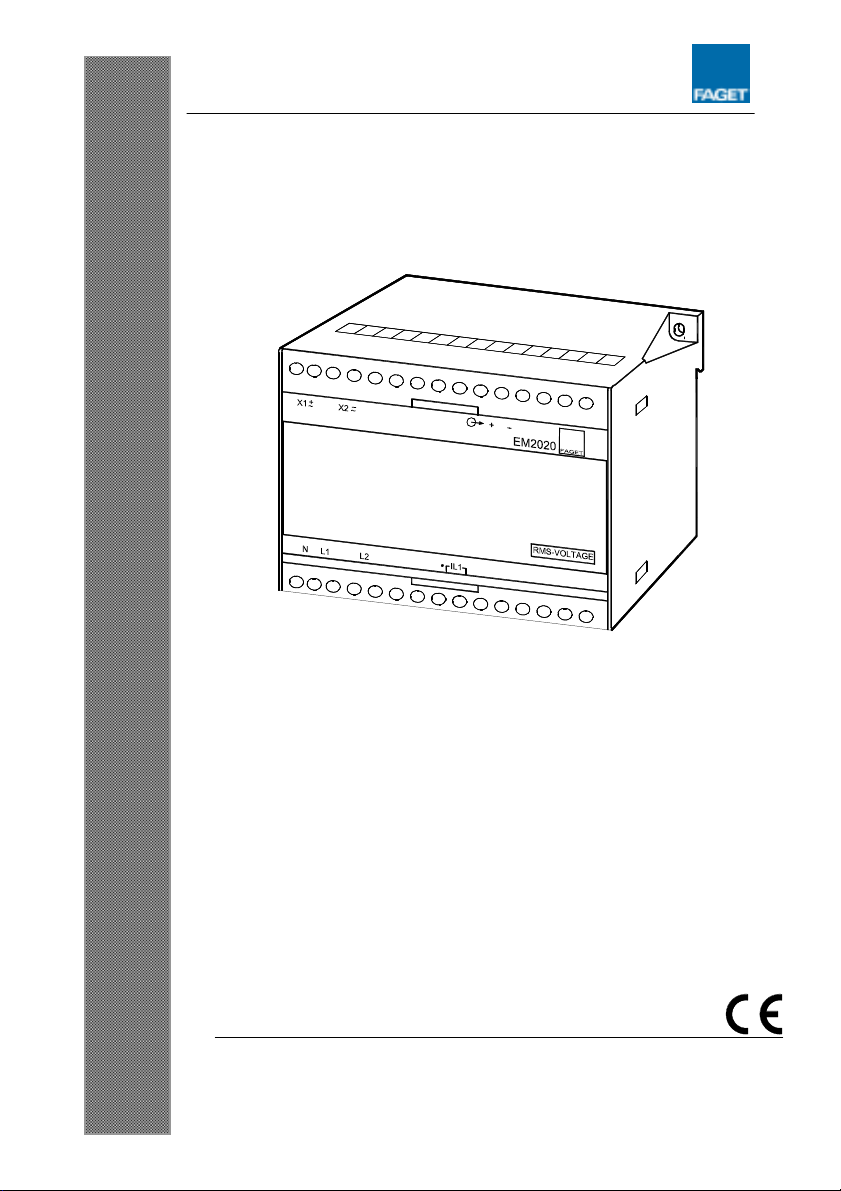
Installation and start up instructions, EM2020
4189300016A (UK)
Technical specifications
Accuracy: Class 0.5 (-10…15…30…55°C) according to IEC 60688
Meas. current (In) 0.75/1.5/3.0/6.0A Meas. range: 0…200% In
In can be set between 0.375…6A
Overload, currents: 20A max., continuously
75A max. for 10 s
240A max. for 1 s
Load: Max. 0.5VA per phase
Meas. voltage (Un): 73/140/254/400V phase to neutral
Meas. range (Un): 30…120%Un(57...400V)
Un can be set between 57…400V
127/240/440/690V phase to phase
Meas. range(Un): 30…120%Un(100...690V)
Un can be set between 100…690V
Overload, voltages: 1.2 x Unmax., continuously, 2 x Unmax. for 10 s
Load: Min. 480k
Frequency range: 30…45…65…80Hz
Note: For fundamental frequency (1. harmonic) outside 20Hz
…80Hz the input is fixed to 0
Indication: Red LED function:
(The LED is located behind the front plate)
Incorrect wiring = constant light, only active for coupling 1W3,
2W3, 3W3(4) and 1var3, 2var3, 3var3(4)
Calibration error = flash frequency 5Hz
Configuration error = flash frequency 1Hz
Other ranges possible
Output: 1 analog output
Standard range: Output (0...100%):
0...1mA, 0...5mA, 0...10mA, 0...20mA, 0...1V, 0...5V, 0...10V
Output (10...100%):
0.1...1mA, 0.5...5mA, 1...10mA, 2...20mA, 0.1...1V, 0.5...5V,
1...10V
Output (20...100%):
0.2...1mA, 1...5mA, 2...10mA, 4...20mA, 0.2...1V, 1...5V,
2...10V
Output (-100...0...100%):
-1...0...1mA, -5...0...5mA, -10...0...10mA, -20...0...20mA,
-1...0...1V, -5...0...5V, -10...0...10V