manuals.online logo
Brands
  1. Home
  2. •
  3. Brands
  4. •
  5. Airmar
  6. •
  7. Transducer
  8. •
  9. Airmar P79 User manual

Airmar P79 User manual

In-Hull, Adjustable Angle Transducer
Model P79
U.S. Patent No. 6,201,767. EP 1 118 074
Applications
• Fiberglass hulls only
• Recommended for high-speed powerboats and racing sailboats
• Accommodates a deadrise angle up to 22°
Tools & Materials
Safety goggles
Dust mask
Adhesive tape
Pole
Detergent (some installations)
Weak solvent (such as alcohol)
Disk sander (some installations)
Thin sealable plastic bag (some installations)
Cable ties (some installations)
Water-based lubricant (such as K-Y® jelly) (some installations)
Angle finder or digital level
Carpenter’s square
Pencil
Silicone sealant (such as GE Silicone Ior Silicone II)
Screwdriver
Petroleum jelly (such as Vaseline® brand)
Propylene glycol (non-toxic antifreeze/coolant) 71ml (2.4 fl. oz.)
Level
Grommet(s) (some installations)
Installation in a cored fiberglass hull (see page 4):
Drill
Hole saw 100mm or 4"
Miniature disk sander
Casting epoxy (Polypoxy #7035/7040) or resin
Paper cup
Stirrer
Mounting Location
About Fiberglass Hulls
The fiberglass hull below the transducer must be solid. Since the
hull absorbs acoustic energy, transmitting through the hull
reduces the transducer’s performance. Fiberglass hulls are often
reinforced in places for added strength or to reduce weight. These
cored areas contain balsa wood or structural foam which are poor
sound conductors. Do not locate the transducer over coring.
Placement
CAUTION: Do not mount the transducer near water intake or
discharge openings or behind strakes, fittings, or hull irregularities
that will disturb the water flow.
Choose a location:
• Where the fiberglass is solid (no air bubbles are trapped in the
fiberglass resin) and where no coring, flotation material, or dead
air space is sandwiched between the inside skin and outer skin
of the hull.
• Where the hull below the transducer will be in contact with the
water at all times.
• Where the water flowing under the hull is smoothest with a
minimum of bubbles and turbulence (especially at high speeds).
• Away from interference caused by power and radiation sources
such as: the propeller(s) and shaft(s), other machinery, other
echosounders, and other cables. The lower the noise level, the
higher the echosounder gain setting that can be used.
• Where the transducer beam will not be blocked by the keel or
propeller shaft(s).
• Where the deadrise angle does not exceed 22°.
• Where there is space inside the vessel for the height of the unit,
tightening the locking ring, and installing the transducer.
Record the information found on the cable tag for future reference.
Part No._________________Date___________Frequency________kHz
INSTALLATION INSTRUCTIONS
WARNING: Always wear safety goggles and a dust
mask to avoid personal injury.
CAUTION: The fiberglass hull below the transducer
must be solid. The transducer will not transmit through
coring material such as foam or balsa wood.
CAUTION: Do not use an epoxy adhesive because it
is too brittle.
CAUTION: Never pull, carry, or hold the transducer by
the cable. This may sever internal connections.
CAUTION: Never use solvents. Cleaners, fuel,
sealants, paint, and other products may contain strong
solvents, such as acetone, which attack many
plastics, greatly reducing their strength.
IMPORTANT: Please read the instructions completely
before proceeding with the installation. These
instructions supersede any other instructions in your
instrument manual if they differ.
Testing the Selected Mounting Location
Establishing a Performance Baseline
The results of this test are used as a basis of comparison to
determine the best in-hull location for the transducer.
1. Take the boat to the maximum depth in which you will be
operating the echosounder. If deep water is not available, find a
location with at least 30m (100').
2. Connect the transducer to the echosounder.
3. Tape the transducer to a pole with the cable side up. Hold it over
the side of the boat with the active face fully submerged and
parallel to the water surface (see Figure 2).
4. Observe the echosounder’s performance and the depth reading.
Testing the Location
While the boat is at the same site (depth of water), test the
transducer inside the hull at the mounting location. Use one of the
methods below:
A.If the transducer will be located near the stern and the boat
has a minimum deadrise angle—Clean away any build-up of
dirt and/or grease using detergent or a weak solvent such as
alcohol. Place the transducer against the hull and allow bilge
water to cover the surface where they touch (see Figure 3-A).
B.For a moderate deadrise angle—If the hull surface is not
smooth, grind it with a disc sander. Place the transducer inside
a thin plastic bag. Partially fill the bag with water and close it
tightly with a cable tie. Wet the surface of the hull and press the
active face of the transducer against it through the bag (see
Figure 3-B).
C.For any location—If the hull surface is not smooth, grind it with a
disc sander. Coat the active face of the transducer with a water-
based lubricant (such as K-Y®jelly). With a twisting motion, press
the face firmly against the hull (see Figure 3-C). After testing,
wipe all traces of the lubricant from the transducer’s face.
Observe the echosounder’s performance, and compare it to the
baseline. Look for a stable depth reading that is similar to the
baseline. Compare the thickness and intensity of the bottom trace.
If the performance is close to the baseline, this is a good mounting
location. Remember, some energy is lost transmitting through the
hull. If the test reading differs markedly from the baseline, you will
need to find another location to install the transducer.
NOTE: If there is no reading or it is erratic, the transducer may be
positioned over coring which is absorbing the acoustic energy.
Choose another location. If no other location is available, check
with the boat manufacturer to be certain coring is present before
proceeding with the instructions for “Installation in a Cored
Fiberglass Hull” on page 4.
2
inboard
Figure 1.
pressure waves
1/3
full keel sailboat
displacement hull
(6-12")
fin keel sailboat
150-300mm
LWL
Best location for the transducer
(Load Waterline Length)
stepped hull
planing hulls
Boat Types (see Figure 1)
•Displacement hull powerboat—Locate 1/3 of the way back
along the LWL and 150–300mm (6–12") off the centerline.
The starboard side of the hull where the propeller blades are
moving downward is preferred.
•Planing hull powerboat—Mount well aft, on or near the
centerline, and well inboard of the first set of lifting strakes to
ensure that the transducer is in contact with the water at high
speeds. The starboard side of the hull where the propeller
blades are moving downward is preferred.
Outboard and I/O—Mount just forward of the engine(s).
Inboard—Mount well ahead of the propeller(s) and shaft(s).
Stepped hull—Mount just ahead of the first step.
•Fin keel sailboat—Mount to the side of the centerline and
forward of the fin keel 300–600mm (1–2').
•Full keel sailboat—Locate amidships and away from the keel
at the point of minimum deadrise angle.
AB C
active face
Figure 2. Establishing a performance baseline Figure 3. Testing the transducer at the selected location
Installation
CAUTION: The base must be liquid-tight. To ensure a tight bond,
the hull surface under and around the base must be smooth, free
of paint or any other finish, clean, and dry.
CAUTION: Do not use an epoxy adhesive because it is too brittle.
CAUTION: The top of the transducer must be level when the
installation is complete.
1. Measure the deadrise angle of the hull at the selected location
using an angle finder or digital level (see Figure 4). Measure
carefully, since the installed transducer must be within 5° of
vertical.
2. The hull surface to be bonded must be smooth and free of paint
or any other finish. If the surface is rough, use a disk sander to
smooth an area 100mm (4") in diameter.
3. To ensure a tight bond, clean and dry both the selected area
and the underside of the base. Remove any dust, grease, or oil
with a weak solvent, such as alcohol.
4. Using a carpenter’s square, draw a line on the hull
perpendicular to the keel through the center of the mounting
location. This will be used as a guideline to orient the base.
5. The numbers on the flange of the base represent deadrise
angles. Identify the number that most closely corresponds to
the deadrise angle of your hull. Find its match on the opposite
side of the flange. Keeping the keel direction arrows on the side
of the base nearest the keel, align the two raised marks
indicating your deadrise angle with the guideline drawn on the
hull (see Figure 5).
6. When you are satisfied that the location of the transducer is
optimal and the orientation of the base corresponds to the
deadrise angle of your boat, apply a generous bead of silicone
sealant to the underside of the flange of the base. (Follow the
sealant manufacturer’s instructions for its use.) Press the flange
firmly in place to form a liquid-tight seal. Allow the sealant to cure.
7. Slide the transducer into the locking ring (see Figure 6). Turn
the transducer until the rib that most closely corresponds to the
deadrise angle of your hull is aligned with the angle indicator on
the locking ring. To secure the transducer to the locking ring,
insert the two screws. Do not over-tighten the screws.
8. Lubricate the O-ring with petroleum jelly (Vaseline®). This will
help to seal the assembly and prevent the fill-liquid from leaking.
Slide the O-ring onto the transducer assembly (see Figure 7).
3
deadrise
parallel to
hull
waterline
perpendicular
to keel
base
flange
keel direction
keel
direction
guideline
keel
arrow
arrow
angle indicator
detail
locking
ring
transducer
ribs
10•
deadrise
angle
Figure 4. Deadrise angle and guideline Figure 5.Aligning the flange of the base
(4°–12° deadrise angle shown)
Figure 6. Joining the transducer to the locking ring
guideline
angle
keel
O-ring
transducer
front view side view
locking
ring
NOTE: Lubricate the O-ring with
petroleum jelly before sliding
it onto the transducer assembly.
Figure 7. Installing the O-ring and identifying the bosses
boss (2)
4
9. After the sealant on the base has cured, pour 71ml (2.4 fl. oz.)
of propylene glycol into the base. Do not over fill. Be sure to
follow the manufacturer’s directions for use.
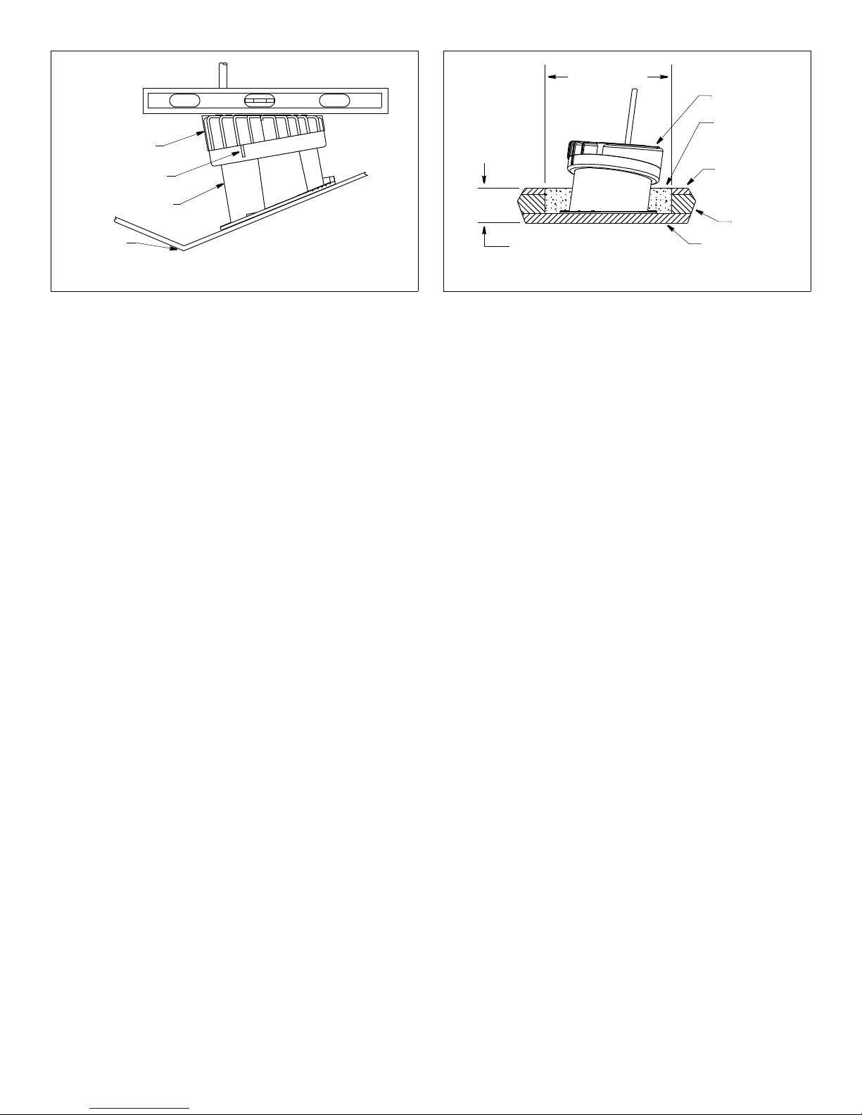
10.With the angle indicator on the keel side, lock the transducer
assembly into the base (see Figure 8). (The bosses on the
locking ring fit into the notches in the base.) Press down and
rotate clockwise until it is seated. When the transducer is
installed correctly, the top will be level. If the deadrise angle is
shallow, the transducer may appear to be level even if it is not.
Use a level to check the installation.
Cable Routing & Connection
CAUTION: If the transducer came with a connector, do not
remove it to ease cable routing. If the cable must be cut and
spliced, use Airmar’s splash-proof Junction Box No. 33-035 and
follow the instructions supplied. Removing the water-proof
connector or cutting the cable, except when using a water-tight
junction box, will void the transducer warranty.
1. Route the cable to the echosounder being careful not to tear the
cable jacket when passing it through the bulkhead and other
parts of the boat. Use grommets to prevent chafing. To reduce
electrical interference, separate the transducer cable from other
electrical wiring and sources of electrical noise. Coil any excess
cable and secure it in place with cable ties to prevent damage.
NOTE: Some transducers are equipped with a short cable,
about 1m (3'), and an extension cable. Be sure to locate the
mated 3 pin connectors well above the bilge waterline. To
facilitate this, use one of the two cable clamps supplied on
either side of the connection.
2. Refer to the instrument owner’s manual to connect the
transducer to the instrument.
Installation in a Cored Fiberglass Hull
Installation in a cored hull is difficult. The objective is to bond the
base to the inside surface of the hull’s outer skin while
preventing any moisture from penetrating the core.
CAUTION: There is no way to determine if the outer skin is solid
(no trapped air bubbles in the fiberglass) at the selected location
before cutting the inner skin.
1. Using a 100mm or 4" hole saw, cut through the inner skin and
the core at the selected location (see Figure 9). The core
material can be very soft. Apply only light pressure to the hole
saw after cutting through the inner skin to avoid accidentally
cutting the outer hull.
2. Remove the plug of core material, so the inner core of the hull is
fully exposed. Sand the inside surface of the outer skin using a
miniature disk sander. Slightly undercut the surrounding coring
if possible.
3. Clean and dry both the inside surface of the outer skin and the
transducer with a weak solvent, such as alcohol, to remove any
dust, grease, or oil.
4. Place the base in the cavity. Fill the gap between the base and
the hull with casting epoxy or resin following the manufacturer’s
directions for its use.
5. After the casting epoxy or resin has cured, proceed with
“Installation”, on page 3.
Replacement Transducer & Parts
The information needed to order a replacement transducer is printed
on the cable tag. Donot remove this tag. When ordering, specify the
part number, date, and frequency in kHz. For convenient reference,
record this information on the top of page one.
Lost, broken, or worn parts should bereplaced immediately.
Base & O-ring Kit 33-268-01
transducer
inner skin
core
outer skin
fill with
casting epoxy
or resin
hull thickness
100mm (4")
Figure 9. Installation in a cored fiberglass hull
Figure 8. Completed installation is level
angle
indicator
keel
transducer
assembly
base
NOTE: top of
transducer
is level
Find more Raymarine products on our website. Find out more about marine electronics and navigation we have.

Other Airmar Transducer manuals

Airmar P66 Instruction Manual

Airmar

Airmar P66 Instruction Manual

Airmar P79S Instruction Manual

Airmar

Airmar P79S Instruction Manual

Airmar P39 Instruction Manual

Airmar

Airmar P39 Instruction Manual

Airmar SS422 Technical Document

Airmar

Airmar SS422 Technical Document

Airmar ST800 Technical Document

Airmar

Airmar ST800 Technical Document

Airmar TRIDUCER P23 Instruction Manual

Airmar

Airmar TRIDUCER P23 Instruction Manual

Airmar P19-12 Instruction Manual

Airmar

Airmar P19-12 Instruction Manual

Airmar B60 User manual

Airmar

Airmar B60 User manual

Airmar Depth & Temperature P66 Instruction Manual

Airmar

Airmar Depth & Temperature P66 Instruction Manual

Airmar P79 Technical Document

Airmar

Airmar P79 Technical Document

Airmar B39 Instruction Manual

Airmar

Airmar B39 Instruction Manual

Airmar StructureScan SS141L-TS Instruction Manual

Airmar

Airmar StructureScan SS141L-TS Instruction Manual

Airmar M192 Instruction Manual

Airmar

Airmar M192 Instruction Manual

Airmar P23 Technical Document

Airmar

Airmar P23 Technical Document

Airmar R99 User manual

Airmar

Airmar R99 User manual

Airmar P19 Instruction Manual

Airmar

Airmar P19 Instruction Manual

Airmar P58 Instruction Manual

Airmar

Airmar P58 Instruction Manual

Airmar Tilted Element B60 Technical Document

Airmar

Airmar Tilted Element B60 Technical Document

Airmar P48W Technical Document

Airmar

Airmar P48W Technical Document

Airmar TRIDUCER P66 Instruction Manual

Airmar

Airmar TRIDUCER P66 Instruction Manual

Airmar TM185HW Technical Document

Airmar

Airmar TM185HW Technical Document

Airmar R599LM Technical Document

Airmar

Airmar R599LM Technical Document

Airmar R299 Technical Document

Airmar

Airmar R299 Technical Document

Airmar R109LH Technical Document

Airmar

Airmar R109LH Technical Document

Popular Transducer manuals by other brands

M-system M5XWTU instruction manual

M-system

M-system M5XWTU instruction manual

Clark Synthesis TST429 installation manual

Clark Synthesis

Clark Synthesis TST429 installation manual

bk ultrasound E13C2 user guide

bk ultrasound

bk ultrasound E13C2 user guide

HBM U5 Series Mounting instructions

HBM

HBM U5 Series Mounting instructions

FIAMA MAT2 User manual and maintenance

FIAMA

FIAMA MAT2 User manual and maintenance

HBM T40MS Mounting instructions

HBM

HBM T40MS Mounting instructions

Greystone Energy Systems LP-S installation instructions

Greystone Energy Systems

Greystone Energy Systems LP-S installation instructions

Airflow PT-LE operating instructions

Airflow

Airflow PT-LE operating instructions

Knick VariTrans P 43000 Series user manual

Knick

Knick VariTrans P 43000 Series user manual

Simrad SUPPORT BEAM DRILLING TEMPLATE - SCHEMA REV... Template

Simrad

Simrad SUPPORT BEAM DRILLING TEMPLATE - SCHEMA REV... Template

S+S Regeltechnik AERASGARD RFTF -CO2 Operating Instructions, Mounting & Installation

S+S Regeltechnik

S+S Regeltechnik AERASGARD RFTF -CO2 Operating Instructions, Mounting & Installation

Sensor Technology TorqSense SGR530 Series user manual

Sensor Technology

Sensor Technology TorqSense SGR530 Series user manual

Balluff BTL266T user guide

Balluff

Balluff BTL266T user guide

halstrup-walcher P29 Original instruction manual

halstrup-walcher

halstrup-walcher P29 Original instruction manual

Thyracont VSP63 operating instructions

Thyracont

Thyracont VSP63 operating instructions

turck IME-AIA-11Ex-Hi/24VDC quick start guide

turck

turck IME-AIA-11Ex-Hi/24VDC quick start guide

WIKA F2301 operating instructions

WIKA

WIKA F2301 operating instructions

HBM T20WN Mounting instructions

HBM

HBM T20WN Mounting instructions

manuals.online logo
manuals.online logoBrands
  • About & Mission
  • Contact us
  • Privacy Policy
  • Terms and Conditions

Copyright 2025 Manuals.Online. All Rights Reserved.