10/15 www.hoentzsch.com U328_UFAUVAextAS102_B_e_091103
Operating Instructions
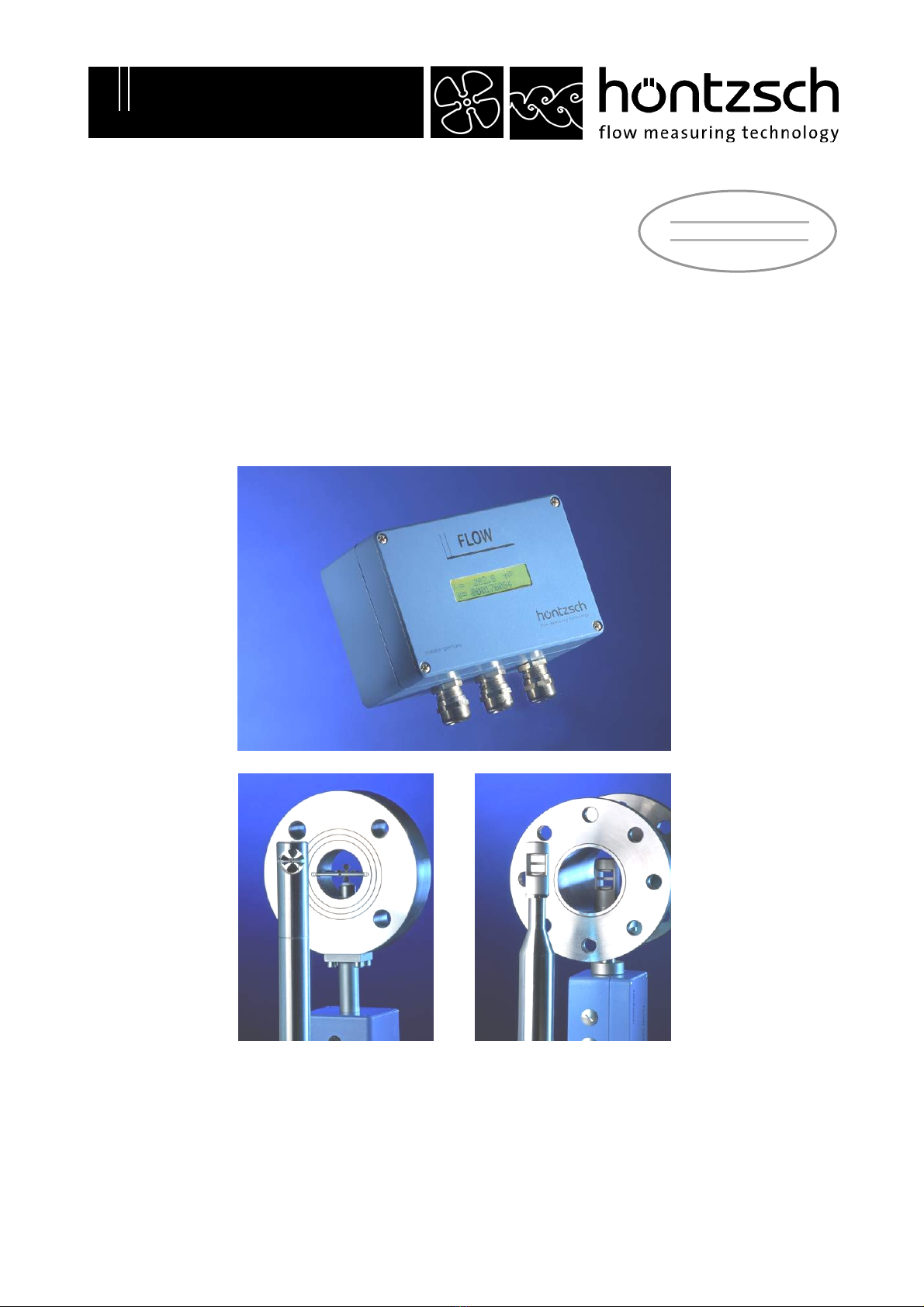
Transducers UFA and UVA in
AS102 housing
6.3 Tips on Electromagnetic Compatibility (EMC)
•all connecting cables are to be kept as short as possible
•with cable routes longer than 30 m or with strong electromagnetic disturbance along the cable route
between sensor and evaluation unit, the use of a double-shielded cable is recommended: to do this
lay inner shielding to one side of the evaluation unit and lay outer shielding on both sides over a large
area with low-impedance connection on the sensor and evaluation unit or on the control cabinet
•do not loop or kink the cable!
•lay non-allocated cable strands on both sides on protective potential!
•lay cables as close to ground as possible,as for example side panels, mounting plates or steel gird-
ers
•when using frequency converters there is a risk of HF interference.Therefore, decouple the power
input of the frequency converter against active emitted interference using a radio interference filter.
This also increases the passive interference resistance of the facility
•between engines and converters use only shielded engine cables with double-sided shielding overlay
•spatially separate cables which emit interference from measuring lines and evaluation units. If
necessary, lay measuring lines in a metallic tubular cable protection
•metallic parts in control cabinets such as sub racks with control electronics or sub plates – to be
connected over a large area and HF-wise suitably conductive
•wire relays, switches and magnetic valves installed in the same circuit,using spark extin-
guisher combinations or over-voltage limiting components.
•apply analog signal cable shielding on one side only – preferably on the evaluation unit - and low re-
sistant. Twist unshielded cables against balanced induction
•apply digital signal cable shielding on both sides over a large area. In the case of potential differences
between these points it is advisable to lay a separate equipotential bonding conductor
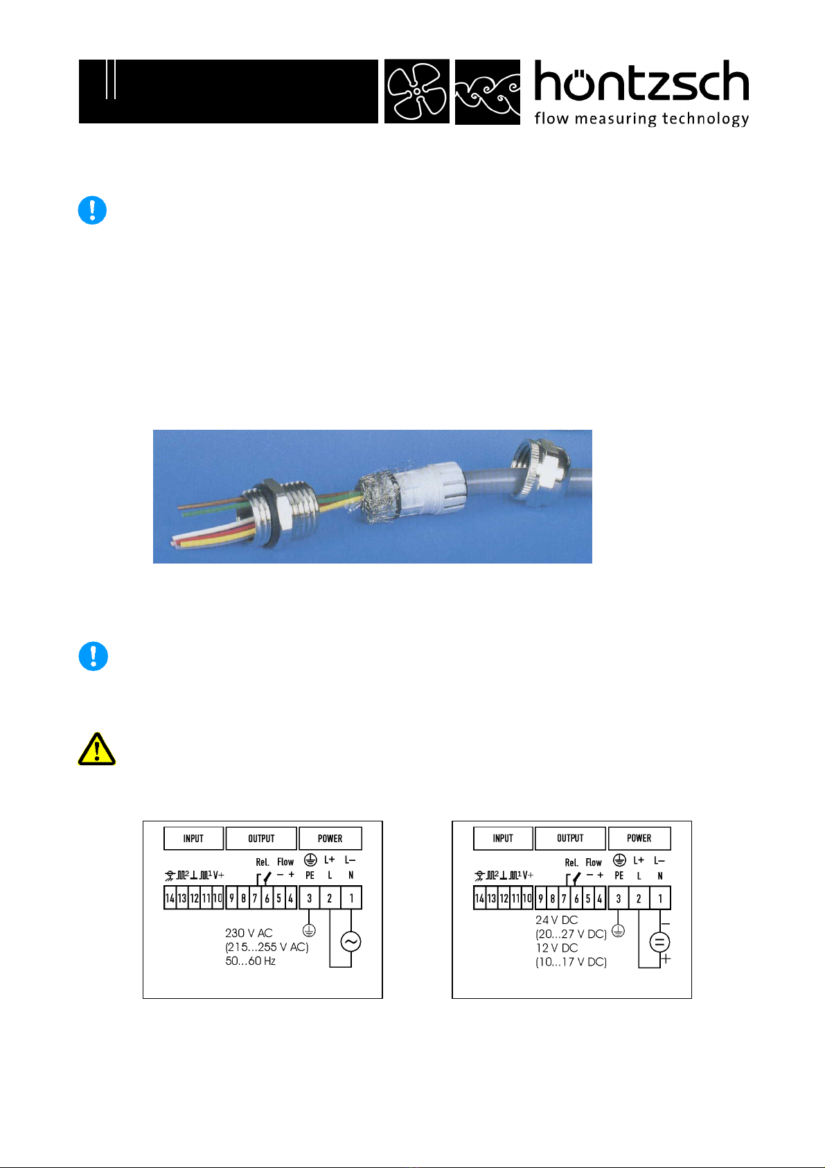
•allow for preferred shielded connector for connections to points of separation of connection ca-
bles.Terminals should be situated in HF-tight housing, with suitable EMC cable bush. Contact outer
shielding of the connection cables to the cable bush.
6.4 Connection Cable
For connecting between sensor and evaluation unit LiYCY cable with simple copper braiding screen can be
used if the cable route is short and there is marginal electromagnetic interference. Over longer distances
or with a high rate of electromagnetic interference, a double-screened cable of type LiYCY-CY should be
used.
Sensor FA 2 (3) x 0.25 mm²
Sensor FAR 3 (4) x 0.25 mm²
Max. permissible conductor resistance per strand is 25 Ohm.
Max. permissible operating capacity between 2 strands is 1.5 nF.
Sensor VA 3 x 0.25 mm2
Max. permissible conductor resistance per strand is 15 Ohm.
Conductor resistances for finely stranded conductors:
approx. 79 Ohm/km with wire cross section 0.25 mm2
approx. 39 Ohm/km with wire cross section 0.50 mm2
approx. 26 Ohm/km with wire cross section 0.75 mm2