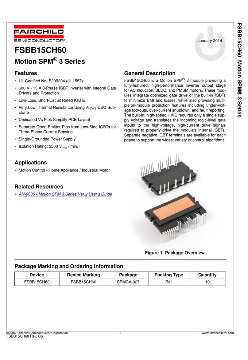
sEcTroN 2
OPERATING INSTRUCTIONS
2.I. FIRST IIME OPERATION
(Figurrt 2-l to 2-41
If this is the ftrst tinte these plug-ins have ever been
Used, then certain initial adjusttncnts rrrust be lnade.
For instructions, reler to Section 5, Maintenance and
Recalibration and to the paragraph indicated, and
nrake the tbllowing adiustnrents.
The following illusrations are designed to aid the
operator in beconring tamiliar with the Delaying
Sweep Plug-ins.
screen each time the sweep runs. This will either cause
the waveform to drift across the screen or to be unintel-
ligible. The sweep theretbre must be triggered by the
input signal, or by sonre signal which bears a fixed
tinre relationship to the input signal. For present Pur-
poses, the starting of each horizontal waveform across
the screen rnay be callerl "triggering the sweep." The
lollowing instructions tell yorr how to select and use
the proper triggering signal for various applications.
2.3. TRIGGEI SOURCE SELECTION
o. lnlernol
For rrrost applications, the sweep may be triggered
by the Y input signal. The only requirement is that
the signal amplitude be sufficient to triSSer the sweeP'
To obtain riggering of the sweep from the input
signal, set the TriSger SOURCE switch to INT. In-
ternal triggering is convenient since no external trig-
gering connections are required. Satisfactory results
are obtained in rnost applications.
b. Extemql
Sornetirrres it is advantageous to rigger the sweeP
with an external signal. Exrcrnal triggering is es-
pecialty useful where signals are going to be sampled
lrom several difierent places within an instrument.
With external riggering, the triggering signal usually
reurains constant in amplitude and shape. Thus, it is
possible to observe the shaping and amplification of a
signal in an external circuit without resetdng the
oscilloscope triggering controls for each observation.
AIso, time and phase relationships between the wave-
forms at difierent points in the circuit can be seen.
For example, if the external riggering signal is de-
rived from ihe waveform at the input to a circuit, the
tirrre relationship and phase of the waveforms at each
1>oint in the circuit are cornpared to the inPut signal
by the displayed waveform.
When a stable, external triggering signal is avail-
able, it is possible to observe and accurarcly measure
jitter of the displayed waveform with respect to the
trigger input signal. This is not possible when the
sweep is triggered internally. A trigger preceding the
signal nray b€ used to externally trigger the oscillo-
scope to display the entire signal.
External triggering should also be used with a dual-
trace amplifier module in the AlTernate mode to
show the proper time relationship between the two
displayed signals. To obtain a stable display, the ex-
ternal triggering signal must have an amplitude of at
Adiuctmcnt
NDT Swecp lcngth
Sweep Col
DA Swecp lcngth
Strobe lniensity qnd
Pqitcrn Correclion
Deloy Zero Adiurimcnt
Dcloy Col Adiurtncnt
Porogrcph
5-9
5-r0
5-l I
5-17
5-t I
5-19
Figures 2-l a
& 2-lb
Figure 2-2
Figure 2-3a
Figure 2-3b
Type 74-13.4, Function of Controls
and Connectors
Type 74-13A, Normal Display
Type 74.134, Triggered Strobe
Display
Type 74-13,{, Delayed Triggered
Display
Figure 2-4a Type 74-13A, Armed Strobe Display
Figure 2-4b Type 74-13A, Armed Delayed Display
Unless otherwise designated, it is presumed that a
Y Amplifler Plug-in module is inserted in the Y cavity
(left-hand side) and the Type 74-l3A Time Base
Plug-in unit is inserted in the X cavity (right-hand
side) of the Main Frame.
We know that you are anxious to get acquainted
with your new instrumenl To aid you in this en-
deavor, you may set up the insrument using the built'
in calibrator signal to demonstrate the effects of the
various conrols on the display.
2.2. SWEEP IRIGGEIING
Two trigger circuits are built into the Delaying
Sweep plug-ins. Each Time Base is provided with its
own separate triggering facility.
To obtain a stable display, the sweep must con-
sistently start at the same time relative to recurring
cycles of the input waveform. If the sweep is allowed
to occur at random or at a rate unrelated to the rate
of occurrence of the input waveform, the displayed
pattern will be traced out at a difterent point on the
2-l


