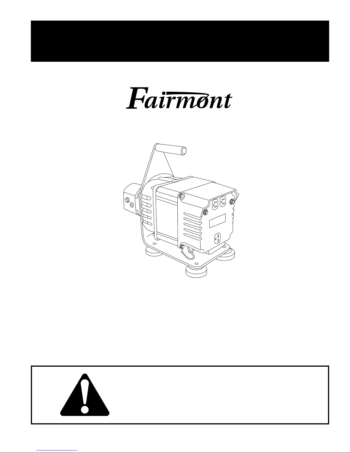
H6635 / 42276 Portable Alternator
Greenlee / A Textron Company 24455 Boeing Dr. • Rockford, IL 61109-2988 USA • 815-397-7070
Description ..................................................................... 2
Important Safety Instructions ......................................3-4
Identification ................................................................... 5
Specifications
Alternator ................................................................... 6
Hydraulic Power Source .........................................6-7
Recommended Hydraulic Fluids ................................ 7
Hoses and Fittings ..................................................... 8
Unit / Hose Connections ............................................ 8
Operation ..................................................................9-10
Maintenance............................................................11-12
Troubleshooting ........................................................... 13
Disassembly ................................................................. 14
Inspection ..................................................................... 15
Assembly...................................................................... 15
Illustration and Parts ...............................................16-17
Accessories (Optional) ................................................. 18
Table of Contents
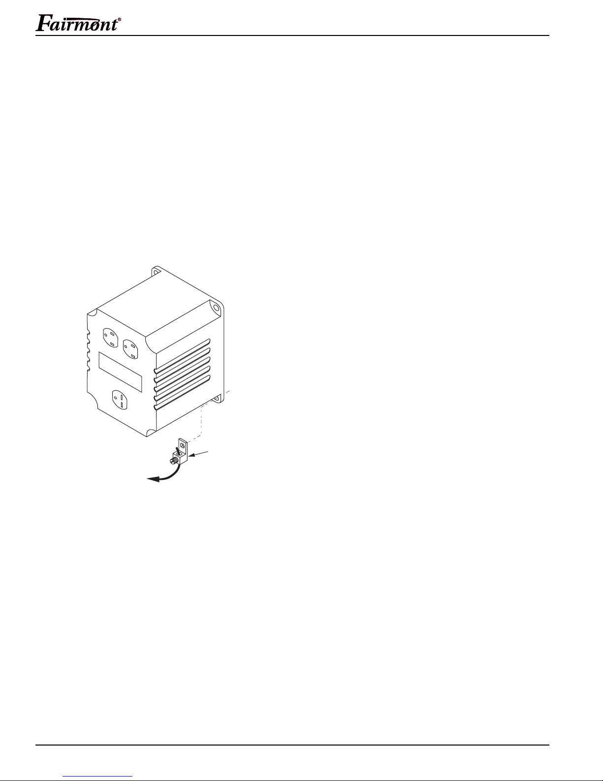
Description
The H6635/42276 Portable Alternator provides instant
electric power for lighting, heaters and other electrical
equipment. It is driven by a hydraulic gear motor and is
able to operate from hydraulic systems with flow rates
from 30-45 l/min (8-12 gpm). The alternator, a 60-cycle,
single-phase unit, is capable of delivering up to 3500
watts of electrical power through its 120 and 240 volt AC
outlets.
The 120 volt duplex receptacle is split so that 15 amps
of current may be drawn from either half of the receptacle.
These outlets may be used along with the 240 volt
receptacle provided the alternator is not overloaded.
A maximum of 14.6 amps may be drawn from the 240
volt receptacle provided it is the only receptacle used.
When using the unit, current must be limited to the
ratings on the nameplates of the equipment being
used. If the 240 volt receptacle is used along with the
120 volt receptacles, the total load drawn must not
exceed the equipment’s nameplate ratings.
Purpose
This instruction manual is intended to familiarize
personnel with the safe operation and maintenance
procedures for the following Fairmont tool:
H6635/42276 Portable Alternator
Keep this manual available to all personnel.
Replacement manuals are available upon request
at no charge.
Safety is essential in the use and maintenance of
Fairmont tools and equipment. This instruction manual
and any markings on the tool provide information for
avoiding hazards and unsafe practices related to the use
of this tool. Observe all of the safety information provided.
KEEP THIS MANUAL
Outlet 1 120 Volts x Amps Draw = Watts #1
Outlet 2 120 Volts x Amps Draw = Watts #2
Outlet 3 240 Volts x Amps Draw = Watts #3
Outlet 4 240 Volts x Amps Draw = Watts #4
Total of all outlets used
must not exceed 3500 watts.
All specifications are nominal and may change as design improve-
ments occur. Greenlee Textron Inc. shall not be liable for damages
resulting from misapplication or misuse of its products.
Safety
Do not discard this product or throw away!
For recycling information, go to
www.greenlee.com.