FAirway V220 Assembly instructions

x2
x2
909920-01
V210 & V220 VINYL RAILING
INSTALLATION GUIDE
* Number of Vinyl Balusters Included in Level Kits:
Square Turned
6' Railing Kit 13 14
8' Railing Kit 18 19
10' Railing Kit 22 24
* Number of Vinyl Balusters Included in Stair Kits:
Square Turned
6' Railing Kit 12 13
8' Railing Kit 17 18
Always use safety equipment
when installing these products.
It is the responsibility of the installer to meet or exceed all code
and safety requirements, and to obtain all required building
permits. These instructions are only a guide and may not
address every circumstance. The deck and railing installer
should determine and implement appropriate installation
techniques for each situation.
Fairway Architectural Railing Solutions shall not be
held liable for improper or unsafe installations.
OPTIONAL FAIRWAY® RAILING BRACKET ADAPTERS
V210 LEVEL Vinyl Railing Kits Include:
2 ea. - 2" x 3-1/2" V210 Vinyl Rail
2 ea. - V210 Aluminum Insert
4 ea. - V210 Mounting Bracket (Bracket and Trim Ring)
1 ea. - Pack S.S. Mounting Screws
* Vinyl Baluster - see grid below
V220 LEVEL Vinyl Railing Kits Include:
1 ea. - V220 Vinyl Top Rail
1 ea. - 2" x 3-1/2" V210 Vinyl Bottom Rail
1 ea. - V220 Aluminum Insert (Top Rail)
1 ea. - V210 Aluminum Insert (Bottom Rail)
2 ea. -V220 Mounting Bracket (Bracket and Trim Ring)
2 ea. - V210 Mounting Bracket (Bracket and Trim Ring)
1 ea. - Pack S.S. Mounting Screws
* Vinyl Baluster - see grid below
V210 STAIR Vinyl Railing Kits Include:
2 ea. - 2" x 3-1/2" V210 Vinyl Rail
2 ea. - V210 Aluminum Insert
4 ea. -
V210
Stair Mounting Bracket (Bracket and Trim Ring)
1 ea. - Pack S.S. Mounting Screws
* Vinyl Baluster - see grid below
V220 STAIR Vinyl Railing Kits Include:
1 ea. - V220 Vinyl Top Rail
1 ea. - 2" x 3-1/2" V210 Vinyl Bottom Rail
1 ea. - V220 Aluminum Insert (Top Rail)
1 ea. - V210 Aluminum Insert (Bottom Rail)
2 ea. - V220
Stair Mounting Bracket
(3/16" S.S. Pins & Screw Plugs)
2 ea. - V210
Stair Mounting Bracket (Bracket and Trim Ring)
1 ea. - Pack S.S. Mounting Screws & Pins
* Vinyl Baluster - see grid below
A - 45º V210 Rail Bracket Adapter
B - 22.5º/45º Internal Bracket
C - 45º V220 Rail Bracket Adapter
D - 22.5º V210/V220 Contour Rail
Bracket Adapter
E - V210 Round Column
Bracket Adapter (6"-10")
F -V220 Round Column
Bracket Adapter (6"-10")
A
C
D
x4
x2 x2
x4
x2 x2
x4
A B C D E F
Check all local building codes for design load requirements for your railing application. FAIRWAY® V200 Series Vinyl Railing is manufactured to the
standards outlined in ASTM F964 and has been tested according to AC174-09 criteria and is approved to meet the requirements for Guardrails as
outlined for pertaining IRC (Residential) and IBC (Commercial) applications as documented in the Code Compliance Research Report, CCRR-0153.
If your railing has any loose dirt on it from the installation, simply hose it off
or wipe with a soft cloth. To remove any stubborn dirt or stains use Simple
Green and #0000 steel wool.
• Measuring tape
• Pencil
• Drill
• 5/32" drill bit
• 7/32" drill bit
• #2 square drive bit
• Power miter saw
• Carbide blade
• Plastic
speed square
Suggested Tools
Cleaning
x2
x*
x* x*
x2
x1 x1
x1
x1
x1 x1
x1 x1
x*
#10 - 2" Stainless Steel Screw • #2 Square Drive
#10 - 1-1/2" Stainless Steel Screw • #2 Square Drive
x16
x8 x4
x8 x8x2
#10 - 3/4" Stainless Steel Screw • #2 Square Drive
x8
x8 x4
x16
#10 - 3/4" Stainless Steel Screw • #2 Square Drive
x8
x4
x2 x2 x1
x2
Baluster
Pocket
Baluster
Pocket
FAIRWAY ARCHITECTURAL RAILING SOLUTIONS ©2017

STEP 1 • POST/MOUNTING SURFACE PREPARATION
Plumb post/mounting surface.
Slide vinyl post sleeve and one piece post trim ring over post.
STEP 2 • BOTTOM RAIL & BRACKET PREPARATION
A) Determine height of bottom rail. This should be no more than 4" and no
less than 2" for 36" high railing and no greater than 2" for 42" high
railing. Make
a pencil mark at bottom of the bottom rail on the post. Measure up 3/8" above
previous mark, then square and
center the bottom of the black mounting bracket.
Mark screw holes in the four (4)
corners of the bracket and then pre-drill four (4)
5/32" holes. Screw the bracket base
into place with four (4) #12 x 1-1/4" pan head
screws. Repeat on opposite post.
B) After the bottom black mounting bracket is in place, measure from bottom
of black mounting bracket up and mark with pencil. Please use the following
measurements in accordance with product style and height:
36" V210 Rail = 31-3/4" • 36" V220 Rail = 31-1/4"
42" V210 Rail = 38-1/4" • 42" V220 Rail = 37-3/4"
This will be the mounting mark for the
bottom of the top black mounting
bracket.
Square and center the top black mounting bracket on mark and pre-drill
four (4) 5/32" holes. Screw into place using four (4) #12 x 1-1/4" for V210 Railing
or four (4) #10 x 2" pan head screws for V220 Railing. Repeat on opposite post.
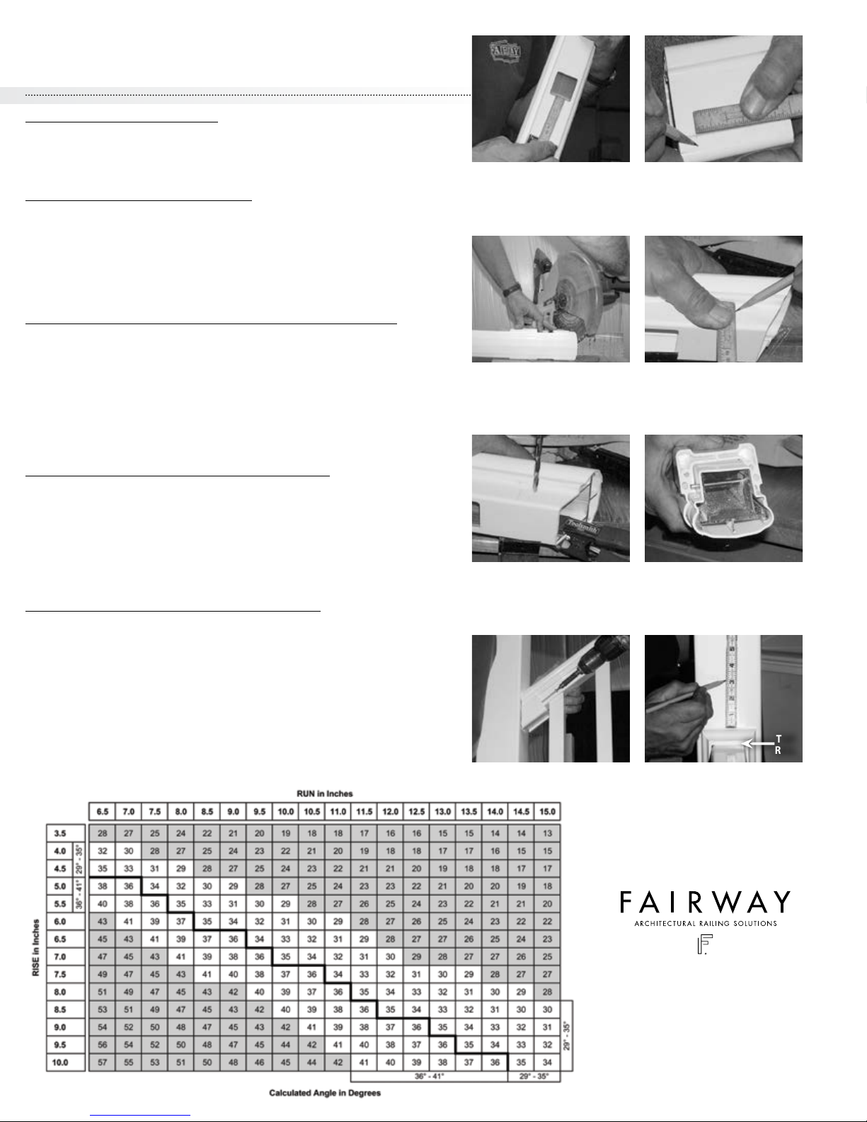
C) Measure the inside span between black mounting brackets for bottom rail.
(Make sure you have equal and maximum amount of spacing between baluster
pocket and post on each end.) Cut bottom rail to length squarely with a power
miter box or hacksaw. You may cut vinyl and aluminum insert at same time.*
STEP 3 • INSTALL BOTTOM RAIL
A) With bottom rail cut to length, slide bracket trim ring onto each end of
bottom rail, flat side towards end, facing post. (TIP: You may want to cut blocks
to proper height for rail to rest on.) Set bottom rail into place and align bottom
rail with bottom rail height bottom mark from Step 2A.
B) With the bottom rail in place, insert one (1) #8 x 1" self-tapping pan head
screw through one of the holes along the side of the black mounting bracket,
through vinyl rail and into aluminum insert. Only one (1) screw per side is
needed. Slide bracket trim ring onto black mounting bracket.
Repeat on opposite post.
NOTE: If bracket trim ring will not snap on black mounting bracket, make sure
mounting screws (bracket to post connection) are not over-tightened.
STEP 4 • INSTALL BALUSTERS & TOP RAIL
A) Measure the inside span between black mounting brackets for top rail. Cut
top rail to length to match bottom rail. If post is plumb, top rail should be same
length as bottom rail. Make sure distance from baluster pocket to post on each
end is the same for both top and bottom rail. Place a baluster in each hole. Slide
bracket trim ring on both ends of top rail, flat side towards end, facing post.
From one end, begin to insert top of balusters into corresponding pocket holes
and be sure rail slides down into black mounting brackets side guides.
B) Once all balusters are in place, the top rail will rest in the black mounting
bracket. Insert one (1) #8 x 1" for V210 railing, (1) #10 x 1" for V220 railing
self-tapping pan head screw through one of the holes along the side of the
black mounting bracket, through vinyl rail and into aluminum insert. Only one
(1) screw per side is needed. Slide bracket trim ring onto black mounting
bracket. Repeat on opposite post.
NOTE: If bracket trim ring will not snap on black mounting bracket, make sure
mounting screws (bracket to post connection) are not over-tightened.
STEP 5 • CUT VINYL POST SLEEVE TO HEIGHT
After your railing is installed, you may wish to trim the top of the vinyl post
sleeves before installing post caps. We recommend measuring up 2-1/2" to
3-1/2"
from the top of the mounting bracket trim ring and making a pencil
mark prior to cutting. NOTE: Finished post height with post cap may be
adjusted for personal preference and appearance. Once all marks are
satisfactory, cut the vinyl sleeve using a hand or power saw. (Be sure to cut top
of post square.)
You are now ready to install your post cap.
Apply a small amount of PVC glue or silicone caulk to the inside lip of the post
cap and mount in place.
STEP 2A STEP 2B
STEP 2B STEP 2C
STEP 2C STEP 3A
STEP 3B STEP 4A
STEP 4A STEP 4B
STEP 2ASTEP 1
STEP 5 STEP 5
TOP
RAIL
*See saw blade manufacturer’s specs for proper blade
NOTE: If V210 rail bracket trim ring will
not snap on black mounting bracket, make
sure bracket to post mounting screws are
not over-tightened.
V210 & V220 VINYL RAILING
INSTALLATION GUIDE

STEP 1 • POST/MOUNTING SURFACE PREPARATION
Plumb post/mounting surface. Slide vinyl post sleeve and post trim ring over post.
(See Rise/Run Chart on next page for proper angle.)
STEP 2 • BOTTOM RAIL & BRACKET PREPARATION
A) Place one end of the bottom rail on deck surface and the other end on the last stair tread nosing.
(Baluster pockets up.)
B) Measure distance from the mounting surface to the first baluster. Make sure you have maximum
and equal distance between baluster pockets at both ends of the bottom rail. With the bottom rail
set in the proper baluster spacing, draw a vertical line with a pencil on the inside of the mounting
surface where the post and rail meet. Repeat on opposite end of rail.
C) With bottom rail marked, deduct 1/4" from each rail end to allow for black mounting bracket.
Cut bottom rail to length. You may cut both aluminum and vinyl at the same time with a power miter
box or hack saw.*
STEP 3 • INSTALL BOTTOM RAIL, BRACKET & TOP RAIL PREPARATION
A) Slide black mounting brackets onto the ends of the bottom rail and center on end of rail. Place
rail with black mounting bracket between posts set to proper height off deck and bottom tread
nosing. Mark the top of black mounting brackets on post.
(Check with local building code for height and opening requirements.)
B)
Remove the black mounting bracket from the ends of bottom rail, square and center brackets
with
the mark on the posts. Mark the screw holes in the four (4) corners of the black mounting bracket.
Pre-drill four (4) 5/32" holes. Install black mounting brackets with four (4) #12 x 1-1/4" pan head
screws.
C) With both black mounting brackets screwed to mounting surfaces, slide bracket trim rings on
end
of rail,
flat side towards mounting surface. (TIP: If pitch is greater than 32° cut along marks on
inside of all V210 rail bracket trim rings.) Set bottom rail into black mounting brackets making sure
rail is centered. (TIP: You may want to cut blocks to proper height for rail to rest on.) Insert one (1) #8
x 1" self-tapping pan head screw through one of the holes along the side of the black mounting
bracket, through vinyl rail and into aluminum insert. Only one (1) screw per side is needed. Slide
bracket trim ring onto black mounting bracket. Repeat on opposite post.
NOTE: If bracket trim ring will not snap on black mounting bracket, make sure mounting screws
(bracket to post connection) are not over-tightened.
D) Insert a baluster into the baluster pocket closest to the post at each end of stair. Set top rail in
place over balusters. Measure the distance from baluster to post at bottom rail and adjust the top
rail to match. Draw a vertical line with a pencil on the inside of the mounting surface where the post
and rail meet. Repeat on opposite end of rail.
STEP 4 • INSTALL BALUSTERS & TOP RAIL FOR V210 VINYL RAILING
(Skip STEP 4 if using V220 rail)
A) With top rail marked, deduct 1/4" from each rail end to allow for black mounting bracket.
Cut top rail to length.
B) Slide black mounting brackets on each end of rail. Insert two (2) end balusters in bottom rail,
match up with top rail and align top rail in between posts. With top rail in place and black mounting
bracket centered on rail ends, mark black mounting bracket position on post.
Remove the black
mounting bracket from the ends of top rail, square and center brackets
with the mark on the posts.
Mark the screw holes in the four (4) corners of the black mounting bracket. Pre-drill four (4) 5/32"
holes. Install black mounting brackets with four (4) #12 x 1-1/4" pan head screws.
C) With black mounting brackets in place, you may now insert your balusters in bottom rail baluster
pockets. With balusters in place, slide bracket trim rings on each end of top rail, flat side towards
mounting surface. Starting at the bottom of stair run, slide top rail into black mounting bracket.
Insert balusters into baluster pockets as you work upward to top of stair. Continue up to top of stair
run. Insert one (1) #8 x 1" self-tapping pan head screw through one of the holes along the side of
the black mounting bracket, through vinyl rail and into aluminum insert. Only one (1) screw per
side is needed. Slide bracket trim ring onto black mounting bracket. Repeat on opposite post.
D) Make sure all four bracket trim ring rings are snapped over black mounting brackets.
NOTE: If bracket trim ring will not snap on black mounting bracket, make sure mounting screws
(bracket to post connection) are not over-tightened.
STEP 2
STEP 3A
STEP 3B
STEP 3C
STEP 1
STEP 3D *See saw blade manufacturer’s specs for proper blade
NOTE: If V210 rail bracket trim ring will
not snap on black mounting bracket,
make sure bracket to post mounting
screws are not over-tightened.
V210 & V220 VINYL RAILING
INSTALLATION GUIDE

STEP 5 • CUT V220 TOP RAILS
With both ends of top rail marked from STEP 3D, place the bottom (baluster
pocket side) against the back stop of the miter box. Match up miter cut with
line marked on top rail and cut top rail to length. You may cut both aluminum
and vinyl at the same time.*
STEP 6 • CUT V220 STAIR BRACKET
A)
Measure the distance from the end of rail to the baluster pocket (so
V220 stair bracket will not cover baluster pocket). Mark bottom of V220 stair
bracket with this measurement. Make sure mounting screws are facing towards
balusters.
B)
Slide V220
stair bracket
onto a piece of scrap V220 rail and cut at same
angle as top rail.
(TIP: Use another
V220
stair bracket to hold railing level in
miter box for a correct angle cut.)
STEP 7 • INSTALL 3/16" S.S. PINS IN V220 STAIR BRACKET
(3/16" S.S. pins keep rail from pulling out of
V220
rail bracket under load.)
A)
With both
V220
stair brackets cut to match top rail, slide
V220
stair bracket
onto top rail and hold flush with end of top rail. Make a mark on both sides of
contour stair bracket.
B)
Remove
V220
stair bracket. Measure from marks toward the end of the top
rail 1/2" and down 1/8" from bottom of bead on the side of top rail. Where the
lines intersect, drill a 7/32" hole through the vinyl and aluminum (make sure
aluminum is flush with vinyl) on both sides of top rail. Slide
V220
stair brackets
onto top rail, insert 3/16" S.S. pin and engage pin into
V220
stair brackets.
STEP 8 • INSTALL BALUSTERS & V220 TOP RAIL
Install all balusters into bottom rail. Start at the bottom of stair run and one
by one insert balusters into top rail. Set rail in place and center on mounting
surface. Insert two (2) #10 x 4" pan head screws into
V220
stair bracket. While
keeping
V220
stair bracket square and centered on mounting surface, start
screw enough to mark mounting surface. Push top rail to one side and pre-
drill a 5/32" hole at same angle as mounting screw. Set rail in place and install
mounting screws. Insert fill plugs, two (2) per
V220
stair bracket, using PVC
glue or silicone caulk to hold in place.
STEP 9 • CUT VINYL POST SLEEVE TO HEIGHT
After your railing is installed, you may wish to trim the top of the vinyl post
sleeves before installing post caps. We recommend measuring up 2-1/2" to
3-1/2"
from the top of the mounting bracket trim ring and making a pencil
mark prior to cutting. NOTE: Finished post height with post cap may be
adjusted for personal preference and appearance. Once all marks are
satisfactory, cut the vinyl sleeve using a hand or power saw. (Be sure to cut
top of post square.)
You are now ready to install your post cap.
Apply a small amount of PVC glue or silicone caulk to the inside lip of the
post cap and mount in place.
STEP 6A STEP 6B
STEP 6B STEP 7B
STEP 7B STEP 7B
TOP
RAIL
STEP 8 STEP 9
www.FairwayRailing.com
*See saw blade manufacturer’s specs for proper blade
FAIRWAY ARCHITECTURAL RAILING SOLUTIONS ©2017
V210 & V220 VINYL RAILING
INSTALLATION GUIDE
This manual suits for next models
1
Popular Indoor Furnishing manuals by other brands

Furniture of America
Furniture of America Harriet CM-DK6845 Assembly instructions

JWA
JWA HINTON 68553 Assembly instruction

Cooper Lighting
Cooper Lighting Metalux M Series Specification sheet

Dream On Me
Dream On Me TB8643 Assembly instruction

nardi
nardi ACQUAMARINA 314 quick start guide

FourStarGroup
FourStarGroup 12505326 Assembly instructions

Romina
Romina 6515 Assembly instructions

Modus
Modus ADLER 8N16F4 Assembly instructions

Seconique
Seconique WHITE CHARISMA HOME BAR TABLE Assembly instructions

Uberhaus
Uberhaus 11S067E Assembly instructions

SAFAVIEH COUTURE
SAFAVIEH COUTURE Fitz SFV4109-K quick start guide

Donco
Donco CAROLINA Assembly instructions