fakro ZWP15 User manual

User manual of ZWP15 controller
Contents
1.Description..........................................................................................................................................................2
2.Installation of ZWP15 controller.........................................................................................................................3
3.Controller programming ....................................................................................................................................4
3.1.Adding device to networ (INCLUDE function)........................................................................................5
3.2.Associating device with a pair of buttons on the controller (ASSOCIATE function)................................6
3.3.Associating another controller with the networ (LEARN MODE)...........................................................7
3.4.Deleting device from a pair of controller buttons on the controller (DELETE function)...........................8
3.5.Excluding device from the networ (EXCLUDE function)........................................................................9
3.6.Restoring default settings in the controller (DEFAULT function)............................................................10
3.7.Removing SECONDARY controller from the networ ...........................................................................10
3.8.Special function ASSAIN A ROUTE........................................................................................................11
4.Technical parameters ........................................................................................................................................11
5.Remote control..................................................................................................................................................12
6.Battery replacement ..........................................................................................................................................13
7.Warranty............................................................................................................................................................14
12.06.01 NC811-GB 1/16 ©2012, FAKRO
GB

1. Description
The ZWP15 (remote control) enables remote control of electronic accessories compatible with the
“Z-Wave” system, e.g. ZWS12 or ZWS30 motors for operating FAKRO roof windows. The ZWP15 controller
can operate up to 15 devices separately. The single button in the upper section (No. 3 – Figures 1) allows
selecting one of the five channels (No. 2 – Figures 1) with which devices can be associated. The fifth channel is
signalized by all 4 LEDs.
The ZWP15 controller is equipped with a two-way “Z-Wave” radio communication radio module.
For communication, the Z-Wave module exploits radio wave frequency of 868,42 MHz. In Figure 1, there is
presented a general view of the ZWP remote control with description of available buttons and signaling.
12.06.01 NC811-GB 2/16 ©2012, FAKRO
Figure 1: ZWP15 remote control
A
Dimension ZWP15
A 157 [mm]
B 38 [mm]
C 19 [mm]
1. Functional button “ n/Ex”.
2. Active channel signaling.
3. “SELECT” button for changing channels.
4. Operating buttons pair No.
5. Operating buttons pair No.
6. Operating buttons pair No.

2. Installation of ZWP15 controller
The holder of ZWP15 controller should be attached to the wall or other permanent building element by means
of two screws driven into cylindrical plugs inserted into openings drilled in the wall.
1. Screw the bottom section of the holder to the wall using the included screws which are driven into plugs
2. Mount the upper part of the holder.
3. Place ZWP15 controller on the holder.
12.06.01 NC811-GB 3/16 ©2012, FAKRO

3. Controller programming
In order to operate FAKRO electronic accessories, featuring the Z-Wave system, by means of the
ZWP15 controllers, it is necessary to:
1. Add the device to the “Z-Wave” networ (INCLUDE function) – see section 3.1
and
2. Associate the device with a selected pair of buttons on the controller with which user wishes to operate
the device (ASSOCIATE function) – see section 3.2.
In one “Z-Wave” networ , there can be included a maximum of 232 devices, i.e. controllers, electronic
accessories for FAKRO roof windows as well as other electronic devices.
Note !!! Each device physically deleted from the networ (e.g. damaged) shall be deleted from the controller's
memory (PRIMARY, SECONDARY), that is, first deleted from a pair of buttons (section 3.4) and then deleted
from the networ (3.5). Appropriate implementation of procedures aims to provide optimal communication
between devices. Disconnecting the device without deleting it from the controller's memory will result in longer
time of reaction of devices on commands and faster running out of batteries. In case of necessity of deleting
damaged device, which deleting from the controller's memory is not possible, it is recommended to re-
configurate the whole networ (all devices). Configuration of the new networ begins with restoring the
controller to factory settings (DEFAULT function), and then EXCLUDE function is used and next we go
further to the section 3 „Controller programming”.
Note !!! When moving the device within the networ , it is recommended to delete it from the controller's
memory (first deleting from a pair of buttons, section 3.4) an then deleting it from the networ (section 3.5) and
re-adding after installation in new wor place.
12.06.01 NC811-GB 4/16 ©2012, FAKRO

3.1. Adding device to network (INCLUDE function)
Adding a device to the “Z-Wave” networ is possible only via “PRIMARY” controller (every
single brand new controller is set as a primary controller by default). In each networ , there is always only one
primary controller and any other added to it is identified as “SECONDARY”. The procedure of device adding
to the networ is presented in Figure 2.
*) Programming error can be caused by:
•no button being pressed within 10 seconds from the controller signaling its readiness for adding a new
device to the networ ;
•long distance between the controller and device being added;
•the device already belonging to other networ . It is necessary to use EXCLUDE function and repeat the
procedure of device adding to the networ .
12.06.01 NC811-GB 5/16 ©2012, FAKRO
Figure 2: Adding device to Z-Wave network
5*. Programming error – two external
diodes flashing for app. 2-3 sec.
4. The controller is signalizing that
the device has been successfully
added to the networ (middle
LEDs on for app. 2-3sec.)
1. Press “In/Ex” button once 2. The controller is signalizing its
readiness for adding a new device
to the networ (external LEDs on
for 10 sec.)
3. Press “P” button on the device
and hold it for 0.5 sec. (see
Installation Manual).
1
Note !!! In the new version of the controller, stopping of each procedure is possible by pressing of „IN/EX” buttons. In
the older version, it is necessary to wait 10 sec. until the moment of signalling the error by the controller or resetting it
by removing batteries.

3.2. Associating device wit a pair of buttons on t e controller (ASSOCIATE function)
Associating the device with a pair of buttons on the controller, which has been already included in
the Z-Wave networ according to section 3.1, ma es it possible to operate the device. This procedure can be
carried out on the primary and secondary controllers. The procedure of associating the device with buttons is
presented in Figure 3.
*) Programming error can be caused by:
•no button being pressed within 10 seconds from the controller signaling its readiness for associating a
new device with the networ ;
•long distance between the controller and device being added;
•device already belongs to another networ or it has not been associated with any networ . It is necessary
to perform EXCLUDE function on the device and repeat INCLUDE and ASSOCIATE functions.
12.06.01 NC811-GB 6/16 ©2012, FAKRO
Figure 3: Device associating with selected air of buttons on controller
3. The controller is signilizing
readiness for associating the
device with a pair of buttons on
the controller (three LEDs on for
10 sec.).
5. The controller is signalizing that the
device has been successfully associated
(LEDs on for app. 2-3 sec.).
1. Select channel on the
controller through which the
device will be operated.
6*. Programming error –
LEDs flashing for app. 2-3
sec.
2. Within 1 sec. press:
- “In/Ex” (1) button once and
then
- the button from this pair pf
buttons which will operate the
device (e.g. 2).
4. Press “P” button on the device and
hold it for 0.5 sec. (see Device
Programming Manual).
1
Note!!! In the new version of the controller, stopping of any procedure is possible by pressing of „IN/EX” buttons. In
older version, it is necessary to wait 10 sec. until the moment of signalling the error by the controller or resetting it by
removing the batteries.

3.3. Associating anot er controller wit t e network (LEARN MODE)
Associating further controllers with the networ ma es them being categorized as “SECONDARY”.
Associating a controller with the Z-Wave networ consists in sending data to it from the PRIMARY controller. The
procedure of controller associating is presented in Figure 4. In order to assure the best possible communication within the
networ and after each its modification (including or removing a device):
•associating another controller with the networ should be performed after associating all devices with the first
controller (“PRIMARY”),
•or performing LEARN MODE again on the “SECONDARY” controller already associated with the networ .
*) Programming error can be caused by:
•failure to enter LEARN MODE on the controller being associated with the networ within 10 seconds
from primary controller signaling its readiness for adding a new device to the networ ;
•long distance between the primary controller and controller being added;
•controller already belonging to another networ . It is necessary to perform DEFAULT procedure with it
and repeat associating with the networ .
12.06.01 NC811-GB 7/16 ©2012, FAKRO
Figure 4: Associating another controller to Z-Wave network
5*. Programming error – two external
LEDs flashing for app. 2-3 sec.
2. Press “In/Ex” button on the
controller (LEARN MODE) which
is to be added to the networ three
times within 1.5 sec.
1. Press “In/Ex” button once on
the PRIMARY controller
3. The controller is signalling
assigning with the networ (two
LEDs on as presented in the
picture for app. 10 sec.).
Secondary
Primary
Primary
Secondary
Primary
Secondary
4. After few seconds, the controller is signalizing that associating with the
networ has been successfully completed (two LEDs on as presented in
the picture for app. 2-3 sec.).
Note !!! In order to operate devices from the „Secondary” controller it is necessary to perform ASSOCIATE function (loo
section 3.2).
Note!!! In the new version of the controller, stopping of any procedure is possible by pressing of „IN/EX” buttons. In older
version, it is necessary to wait 10 sec. until the moment of signalling the error by the controller or resetting it by removing the
batteries.

3.4. Deleting device from a pair of controller buttons on t e controller (DELETE function)
This function deletes from controller's memory the device associated with a pair of buttons on a
selected channel. However, it does not remove the device form the “Z-Wave” networ . This function is
accessible from PRIMARY and SECONDARY controllers. The procedure of device deleting form a pair of
controller buttons is presented in Figure 5.
*) Programming error can be caused by:
•failure to press programming button within 10 seconds from controller signaling its readiness for
deleting the device from selected pair of buttons;
•long distance between the controller and device.
12.06.01 NC811-GB 8/16 ©2012, FAKRO
Fig. 5: Deleting device from a air of buttons on the controllers
4. Press “P” button on the device and hold
it for 0.5 sec. (see Device Programming
Manual).
2. Within 1.5 sec., press:
- “In/Ex”(1) button twice and then
- the button from this pair of buttons
which operates the device to be
removed (e.g. 2).
6*. Programming error –
LEDs flashing for app. 2-3
sec.).
1. Select remote control channel
through which the device to be
removed is operated.
5. The controller is signalizing
successful device deleting (three
LEDs on for app. 2-3 sec.).
3. The controller is signalising
readiness for device deleting (three
LEDs on for 10 sec.).
1
Note!!! In the new version of the controller, stopping of any procedure is possible by pressing of „IN/EX” buttons. In
older version, it is necessary to wait 10 sec. until the moment of signalling the error by the controller or resetting it by
removing the batteries.

3.5. Excluding device from t e network (EXCLUDE function)
Excluding the device from the “Z-Wave” networ is possible only with the use of PRIMARY
controller (e.g. ZWP remote control). In each networ there is always only one primary controller and every
other is categorized as SECONDARY. The procedure of device excluding from the networ is presented in
Figure 6.
*) Programming error may be caused by:
•failure to press the programming button within 10 seconds from controller signaling its readiness for
excluding the device from the networ ;
•long distance between the controller and device being excluded.
Note !!! Each device physically deleted from the networ (e.g. damaged) shall be deleted from the controller's
memory (PRIMARY, SECONDARY), that is, first deleted from a pair of buttons (section 3.4) and then deleted
from the networ (3.5). Appropriate implementation of procedures aims to provide optimal communication
between devices. Disconnecting the device without deleting it from the controller's memory will result in longer
time of reaction of devices on commands and faster running out of batteries. In case of necessity of deleting
damaged device, which deleting from the controller's memory is not possible, it is recommended to re-
configurate the whole networ (all devices). Configuration of the new networ begins with restoring the
controller to factory settings (DEFAULT function), and then EXCLUDE function is used and next we go
further to the section 3 „Controller programming”.
Note !!! When moving the device within the networ , it is recommended to delete it from the controller's
memory (first deleting from a pair of buttons, section 3.4) an then deleting it from the networ (section 3.5) and
re-adding after installation in new wor place.
12.06.01 NC811-GB 9/16 ©2012, FAKRO
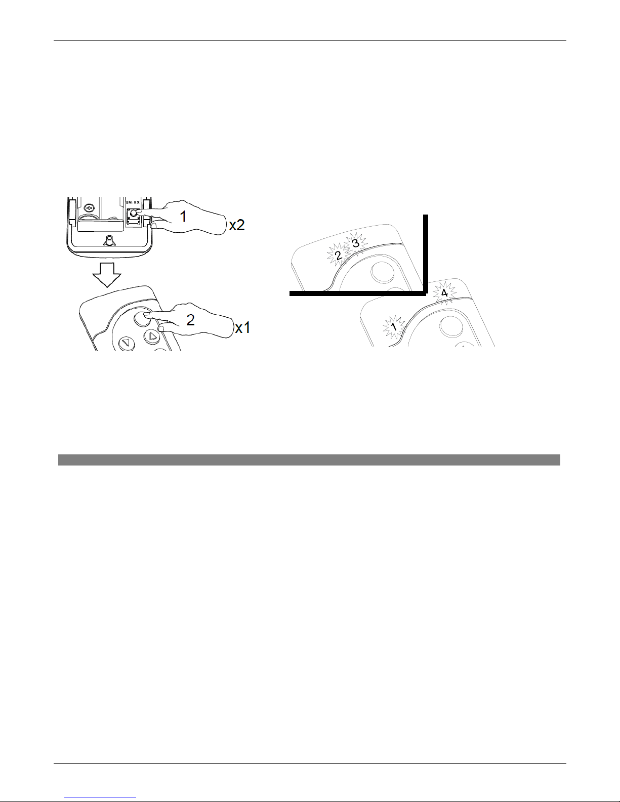
Figure 6: Excluding device from Z-Wave network
5*. Programming error – two
middle LEDs flashing for app. 2-3
sec.
4. The controller is signalizing that the
device has been excluded successfully
(two external diodes on for app. 2-3
sec.).
1. Press “In/Ex” button twice
within 1 sec.
3. Press “P” button on the device and
hold it for 0.5 sec. (see Device
Programming Manual).
2. The controller is signalizing its
readiness for excluding the device
from the networ (two middle
LEDs on for 10 sec.).
1
Note!!! In the new version of the controller, stopping of any procedure is possible by pressing of „IN/EX” buttons. In
older version, it is necessary to wait 10 sec. until the moment of signalling the error by the controller or resetting it by
removing the batteries.

3.6. Restoring default settings in t e controller (DEFAULT function)
Restoring default settings of the controller leads to the following information being deleted from its
memory:
•networ , to which SECONDARY controller has been added;
•devices in the networ for PRIMARY controllers;
•devices associated with pairs of buttons for PRIMARY and SECONDARY controllers.
After performing DEFAULT procedure the SECONDARY controller will be set as PRIMARY.
3.7. Removing SECONDARY controller from t e network
Removing this controller from the networ consists in restoring default settings with the use of DEFAULT
function.
12.06.01 NC811-GB 10/16 ©2012, FAKRO
Figure 7: Restoring default settings in controller
1. Within 1.5 sec. press:
- “In/Ex” button twice (1) and then
- SELECT button (2) once
2. The controller is signalizing restoring default
settings – alternate flashing of middle and
external LEDs for app. 1-2 sec.
Note!!! In the new version of the controller, stopping of any procedure is possible by pressing of „IN/EX” buttons. In
older version, it is necessary to wait 10 sec. until the moment of signalling the error by the controller or resetting it by
removing the batteries.

3.8. Special function ASSAIN A ROUTE
Note !!! All devices ta ing part in the below procedure must belong to the same networ (must have the same HOME
ID).
It is possible to use the controller (ZWK1, ZWK15, ZWP15) to configure the device being outside the direct
range of the networ , transferring NODE info of the device which is to be controlled to the controlling device memory
(controller), to archieve that use ASSAIN A ROUTE Rysunek 8.
4. Technical parameters
Technical parameters
Power supply CR2450, 3V DC
Working temperature (+5OC) to (40OC)
Working range Up to 40 [m]
Working frequency 868,42 MHz
12.06.01 NC811-GB 11/16 ©2012, FAKRO
Figure 8: Function ASSAIN A ROUTE
Note!!! In the new version of the controller, stopping of any procedure is possible by pressing of „IN/EX” buttons. In
older version, it is necessary to wait 10 sec. until the moment of signalling the error by the controller or resetting it by
removing the batteries.
Note!!! Information on how to call up the function ASSAIN A ROUTE by the use of devices of other manufacturers will
be found in their instructions for the particular devices.
1
1
1
2
5
Press for
1 sec
1
2
4
3
6
1. Press the sequence of buttons on the controller
within 1.5 sec :
- press the “IN/EX” button and then
- the “SEL” button
2. Readiness to transfer NODE INFO to other
controller (diode (1,2) lights up for 10 sec)
3. Press the programming button on the controller
for 1 second
4. Admitting NODE INFO to the memory is
signalled by the controller (diode (3,4))
5. Start the procedure of device adding to the group
on the target controller (Associate function). Press
the sequence of buttons on the controller within 1
sec:
- press the “IN/EX” button on the controller briefly
and then
- one of the pair of buttons
6. Wait for confirmation of the execution (transfer)
NODE INFO
7. Confirmation of calling up the function on the
main controller (diodes (1,2,3,4))
7
1
Then within 1 sec

5. Remote control
Note!!! Each command sent from the remote control to the accessory is preceded by a period of accessory awa ening. This
period usually lasts about 0.3 s. In practice, this manifest in delayed reaction lasting for about 0.5 s. When the accessory remote
controlling, 5 commands can be used:
•Close – in ZWP, ZWK controllers is activated after short (about 0.5 sec.) pressing of „close” button on the controller
and causes the roller shutter launching into the closing direction until the motor reaches the end position, which means
that the accessory is completely closed
•Open – in ZWP, ZWK controllers is activated after short (about 0.5 sec.) pressing of „open” button on the controller
and causes the accessory launching into the opening direction until the motor reaches the end position, which means
that the accessory is completely open
•Start to close – in ZWP, ZWK controllers is activated after longer (more than 0.5 sec.) holding of „close” button and
causes the accessory launching into the closing direction until releasing of „close” button
•Start to open – in ZWP, ZWK controllers is activated after longer (more than 0.5 sec) holding of „open” button and
causes the accessory launching into the opening direction until releasing of „open” button
•Stop closing/opening – in ZWP, ZWK controllers is activated after releasing of „open” button or „close” button with
earlier issued command „Start closing”/ „Start opening”. In practice it means, that in order to stop the roller shutter at
any position, it is necessary to press particular button and hold until reaching of the desired position, or launching the
roller shutter into desired direction by short pressing of appropriate button and then stopping it by pressing (longer than
0.5 sec) and then releasing of the same button.
12.06.01 NC811-GB 12/16 ©2012, FAKRO
Figure 9: Methods of remote control
=0,50 [s]
<0,50
min 0,5 [s]
[s]<0,50

6. Battery replacement
With standard controller use (four times a day), the battery should theoretically ensure correct
device functioning for the period of 2 years, assuming that the programming procedure has been performed
only once. Multiple device programming shortens the battery life.
1. emove the back section of the casing.
2. eplace the battery with a new on.
3. einstall the back section of the casing and screw it down in.
12.06.01 NC811-GB 13/16 ©2012, FAKRO

7. Warranty
The manufacturer guarantees correct device functioning. It also underta es to repair
or replace the device if its defects result from material or structural faults. The warranty period
is 24 months from the purchase date, fulfilling the following conditions:
●Installation has been performed by an authorised individual, as per manufacturer
recommendations.
●Seals remain intact and no unauthorised structural changes have been made.
●The device has been used in accordance with its intended use as per user manual.
●Damage is not a result of improperly made electrical system or atmospheric phenomena.
●The manufacturer is not liable for damage which occurred as a result of improper use or
mechanical damage.
In case of failure, the device must be submitted for repair with a Warranty Card. Defects
revealed within the warranty period will be removed free of charge no longer than 14 days after
accepting the product for repair. Warranty and post-warranty repairs are performed by the
manufacturer i.e. FAKRO PP. Sp. z o.o.
Quality Certificate:
Device
Model............................................................................................................................................
Serial Number...............................................................................................................................
Seller.............................................................................................................................................
Address.........................................................................................................................................
Date of Purchase.............................................................................................................................
...............................................................................................................
Signature (stamp) of installing person
12.06.01 NC811-GB 14/16 ©2012, FAKRO

12.06.01 NC811-GB 15/16 ©2012, FAKRO

FAKRO PP Sp. z o.o.
ul. Węgierska 144A
33-300 Nowy Sącz
Polska
www.fakro.com
tel. +48 18 444 0 444
fax. +48 18 444 0 333
12.06.01 NC811-GB 16/16 ©2012, FAKRO
Table of contents
Other fakro Remote Control manuals