FALCOM FOX User manual

THIS DOCUMENT IS AVAILABLE AT HTTP://WWW.FALCOM.DE/
.
FOX
Hardware manua
PRELIMINARY
Version: 1.0.0; Created: Tuesday 4 December 2007

FOX HARDWARE MANUAL - PRELIMINARY - VERSION 1.0.0
Tab e of contents
1 INTRODUCTION.................................................................................5
1.1 General......................................................................................................................5
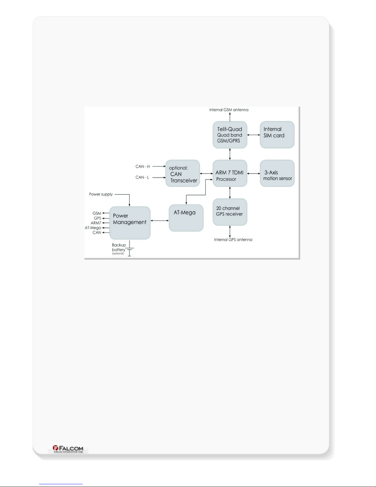
1.2 Circuit concept.........................................................................................................6
1.3 Related documents..................................................................................................8
2 SECURITY.......................................................................................9
2.1 General information.................................................................................................9
2.2 Exposure to RF energ ............................................................................................9
2.3 Efficient modem operation....................................................................................10
2.4 Driving.....................................................................................................................10
2.5 Electronic devices..................................................................................................10
2.6 Vehicle electronic equipment...............................................................................10
2.7 Medical electronic equipment...............................................................................10
2.8 Aircraft.....................................................................................................................10
2.9 Children...................................................................................................................11
2.10 Blasting areas.......................................................................................................11
2.11 Potentiall explosive atmospheres....................................................................11
2.12 Non-ionizing radiation.........................................................................................11
3 SAFETY STANDARDS.......................................................................12
4 TECHNICAL DATA...........................................................................13
4.1 Product features.....................................................................................................13
4.1.1 Power consumption............................................................................................14
4.1.2 Operating temperatures......................................................................................14
4.1.3 GSM/GPRS features..........................................................................................15
4.1.4 GPS features......................................................................................................16
4.2 NMEA data message..............................................................................................17
5 FOX APPLICATION INTERFACE..........................................................18
5.1 Power suppl ..........................................................................................................18
5.1.1 Power suppl pins (1 and 2) on the 8-pin connector..........................................18
5.1.2 Automatic shutdown...........................................................................................18
5.2 Determining the External Equipment T pe.........................................................18
6 HARDWARE INTERFACES..................................................................19
6.1 8-wire connector, pin assignments......................................................................20
6.1.1 8-pin connector pinout........................................................................................20
6.1.2 Special pin description (Pins 4, 5, 6)..................................................................21
6.1.2.1 How to use these pins as analog inputs.................................................................................21
6.1.2.2 How to use these pins as digital Inputs (Pin 4, 5, 6)..............................................................22
6.1.2.3 How to use these pins as digital outputs (Pin 4, 5, 6)............................................................23
6.1.2.4 How to use IGN pin(pin 3)......................................................................................................24
6.1.2.5 Se ial communication signals (RxA and TxA)........................................................................25
6.2 SIM card interface (Molex-91228-0002)................................................................25
6.3 LED’s description...................................................................................................26
This confidential document is a property of FALCOM and may not be copied or circulated without previous permission.
Page 2 of 31

FOX HARDWARE MANUAL - PRELIMINARY - VERSION 1.0.0
6.4 Interface E (Mounting holes).................................................................................26
6.4.1.1 Mounting the FOX device ......................................................................................................27
7 HOUSING.....................................................................................28
8 RF EXPOSURES............................................................................29
9 APPENDIX....................................................................................30
9.1 Schematics.............................................................................................................30
9.1.1 Installation guidance for 8-wire cable connector................................................30
9.2 What should be considered when using the FOX device..................................31
Version history:
N umber Author Cha ges Cha ge date
1.0.0 F. Beqiri -Initial version. 04/12/2007
This confidential document is a property of FALCOM and may not be copied or circulated without previous permission.
Page 3 of 31

FOX HARDWARE MANUAL - PRELIMINARY - VERSION 1.0.0
Cautio s
Information furnished herein by FALCOM is accurate and reliable. However no
responsibility is assumed for its use.
Please read carefully the safety precautions.
If you have any technical questions regarding this document or the product
described in it please contact your vendor.
General information about FALCOM and its range of products are available at the
following Internet address: http://www.falcom.de/
Trademarks
Some mentioned products are registered trademarks of their respective
companies.
Copyright
This document is copyrighted by FALCOM WIRELESS COMMUNICATIONS GmbH with all
rights reserved. No part of this documentation may be produced in any form
without the prior written permission of FALCOM WIRELESS COMMUNICATIONS GmbH.
FALCOM WIRELESS COMMUNICATIONS GmbH.
No patent liability is assumed with respect to the use of the information contained
herein.
This confidential document is a property of FALCOM and may not be copied or circulated without previous permission.
Page 4 of 31

FOX HARDWARE MANUAL - PRELIMINARY - VERSION 1.0.0
1 INTRODUCTION
This product manual is only addressed to qualified personnel which is well skilled in
electronical/electrical installation and not addressed to private consumers/end user.
The installation implementing or setting into operation of the product can only be
performed by this qualified personnel.
The status of the product described in the data sheet may have changed since
publication of the data sheet and therefore information in this data sheet on product
status may be outdated. The latest information of the product is available on the
download area of the FALCOM website.
1.1 General
FALCOM is using state-of-the-art technology to develop unique low-cost devices
which more effectively manage assets and vehicle tracking than current systems. FOX
is a new telematics product designed to be more flexible and efficient for vehicle
management and especially to meet the needs of tracking controlling and
monitoring vehicles with an outstanding safety and security. The FOX terminal comprises
an embedded configurable software that provides even greater performance and
flexibility for its users and system integrators to develop high-performance applications
that allow the tracking of vehicles over the Internet/TCP. The device concept is
targeting for direct implementation as a mobile client in a wide range of high volume
low-cost flexible system solutions like
AVL fleet management vehicle security and
recovery
and
other related area
. The tracking functionality of the embedded mobile
client application is combined with variety of alert messaging capabilities. The
configurable alert messages contain current position and status report and use 3 multi-
function I/O. In addition to that two predefined digital inputs are detecting ignition line
and main power (car battery) failure and so you may handle these events and use as
notification.
By default FOX is offered without internal battery. Shall you need a FOX device
with an internal battery please see “Ordering Guide” and choose one that meets
your specific requirements.
The housing of the new FOX device offers IP65 protection
(optional) and can be operated at ambient temperatures up to +85°C
.
The embedded software the embedded software can be controlled b word like
“PFAL” commands needed for executing particular actions reading or setting
particular configurations. These commands are valid for all kinds of operations including
SMS, CSD, TCP and SMTP.
FOX provides Geofence features for territory management route verification
prohibited locations parking area and more with exception reporting to a wide variety
of events such as arrivals departures deliveries pick-ups illegal entries unauthorized
movement etc. FOX contains a data-logger that enables it to archive unique locations
in sequence for up to 45 days for later analysis and evaluation (for example archive
interval up to 20 sec.).
The physical interface to the terminal application is made through integrated
connector. It is required for controlling the terminal receiving GPS location data
transferring data and audio signals and providing power supply lines. FOX provides 1
serial interface giving you maximum flexibility for local use.
This confidential document is a property of FALCOM and may not be copied or circulated without previous permission.
Page 5 of 31

FOX HARDWARE MANUAL - PRELIMINARY - VERSION 1.0.0
FOX is equipment that can be configured and integrated onto any asset platform
including:
1. Trailers
2. Trucks
3. Delivery vans
4. Rail cars
5. as well as other industrial monitoring installations.
and it can be used in a variety of applications including:
•
Real time online tracking
•
Fleet management / monitoring
•
Security / emergency services
•
Real time satellite navigation
•
Territory management
•
Personalized drivers logbook
•
Route verification
•
Trip management / distance calculations
•
Theft protection
•
Toll collection / pay as you drive
The FOX - EVALKIT provides an easy and efficient way to evaluate and configure all
system parameters of the mobile client. The configuration of the FOX can be done via
local serial link or remotely via the GSM network or GPRS/TCP/Internet. All of these
features are perfectly integrated in a device concept which significantly reduces time
to-market and provides low cost tracking and security solutions.
1.2 Circuit concept
The FOX architecture includes the following major functional components (
a block
diagram is available below
):
ARCHITECTURE INTEGRATES:
High-performance Quad-Band GSM/GPRS core (operating at 26MHz)
20 parallel channel low-power GPS core (operating at L1 1575.42 MHz and
C/A code 1 023 MHz chip rate)
ARM7TDMI Processor (at speed 25MHz) that controls all functions of the
system
Internal SIM card reader (
1.8/3V SIM ca ds
)
Internal GSM antenna
Internal GPS antenna
OPTIONS TO FOX
CAN Interface
3D motion
sensor
Micro-SD-Card
This confidential document is a property of FALCOM and may not be copied or circulated without previous permission.
Page 6 of 31

FOX HARDWARE MANUAL - PRELIMINARY - VERSION 1.0.0
Rechargeable Li-Polymer battery (see Ordering Guide)
PHYSICAL INTERFACES:
Power supply line
3 x Multi-line I/O
1 x Ignition;
RS232 port
Figure 1: FOX block diagram
This confidential document is a property of FALCOM and may not be copied or circulated without previous permission.
Page 7 of 31

FOX HARDWARE MANUAL - PRELIMINARY - VERSION 1.0.0
1.3 Related documents
Some others PDF documents such as FCC approval application notes Certificate
of Conformity R&TTE etc. are also available on the Web at: http://www.falcom.de/ in
the published download area.
In addition to this document the following files comprise the full set of FALCOM FOX
product manuals:
NR PDF file ame Descriptio
[1] SteppIII_fox_bolero_lt_PFAL_Configuration_Com
mand_Set.pdf
Contains the description of the internal firmware and the supported
Configuration Command Set for the FALCOM STEPPIII, FOX and
BOLERO-LT.
[2] AppNotes_Transform_histor _data.pdf Contains information of how to transform histor data that are being
transmitted from FOX via TCP connection.
[3] AppNote_Remote_update.pdf Contains information of how to upgrade FALCOM AVL devices device
to a new firmware revision remotel via TCP.
[4] AppNotes_connecting_a_bar_code_scanner.pdf Describes how to connect a bar code scanner to a STEPPII,
STEPPIII, FOX etc. and store or transmit the scanned data.
[5] AppNotes_in_vehicle_mounting.pdf This document provides all the necessar information to allow our
FALCOM product to be properl and safel installed.
These PDF files are viewable and printable from Adobe Reader. If you do not have
the Adobe Reader installed you can download it from
http://www.adobe.com.
This confidential document is a property of FALCOM and may not be copied or circulated without previous permission.
Page 8 of 31

FOX HARDWARE MANUAL - PRELIMINARY - VERSION 1.0.0
2 SECURITY
IMPORTANT FOR THE EFFICIENT AND SAFE OPERATION OF YOUR GSM-MODEM READ
THIS INFORMATION BEFORE USE!
Your cellular engine FOX is one of the most exciting and innovative electronic
products ever developed. With it you can stay in contact with your office your
home emergency services and others wherever service is provided.
This chapter contains important information for the safe and reliable use of the FOX
device. Please read this chapter carefully before starting to use the cellular engine
FOX.
2.1 General information
Your FOX device utilizes the GSM standard for cellular technology. GSM is a newer
radio frequency („RF“) technology than the current FM technology that has been
used for radio communications for decades. The GSM standard has been
established for use in the European community and elsewhere. Your FOX is actually
a low power radio transmitter and receiver. It sends out and receives radio
frequency energy. When you use your modem the cellular system handling your
calls controls both the radio frequency and the power level of your cellular
modem.
For the use of the acquired devices SIM cards are needed which are not included
in the scope of delivery of the device. The SIM cards can be acquired e.g. by
specific providers. From the use of the SIM cards can result additional costs which
are to be borne by the purchaser (client) of the devices. The seller does not cover
the extra costs for the use of the devices. The seller gives no recommendation for
the use of specific SIM cards and does not liable also for the fact that the devices
are usable with all available SIM cards. The seller also covers no other costs that
are needed for the application of the customer in connection with this device.
2.2 Exposure to RF energy
There has been some public concern about possible health effects of using a GSM
modem. Although research on health effects from RF energy has focused for many
years on the current RF technology scientists have begun research regarding
newer radio technologies such as GSM. After existing research had been
reviewed and after compliance to all applicable safety standards had been
tested it has been concluded that the product is fit for use.
If you are concerned about exposure to RF energy there are things you can do to
minimize exposure. Obviously limiting the duration of your calls will reduce your
exposure to RF energy. In addition you can reduce RF exposure by operating your
cellular modem efficiently by following the guidelines below.
This confidential document is a property of FALCOM and may not be copied or circulated without previous permission.
Page 9 of 31

FOX HARDWARE MANUAL - PRELIMINARY - VERSION 1.0.0
2.3 Efficient modem operation
In order to operate your modem at the lowest power level consistent with
satisfactory call quality please take note of the following hints.
•
If your device has an extendible antenna extend it fully. Some models allow
you to place a call with the antenna retracted. However your FOX operates
more efficiently with the antenna fully extended.
•
Do not hold the antenna (if externally connected) when the modem is „IN
USE“. Holding the antenna affects call quality and may cause the modem to
operate at a higher power level than needed.
2.4 Driving
Check the laws and regulations on the use of cellular devices in the area where
you drive. Always obey them. Also when using your FOX while driving please pay
full attention to driving pull off the road and park before making or answering a
call if driving conditions so require. When applications are prepared for mobile use
they should fulfil road-safety instructions of the current law!
2.5 Electronic devices
Most electronic equipment for example in hospitals and motor vehicles is shielded
from RF energy. However RF energy may affect some malfunctioning or improperly
shielded electronic equipment.
2.6 Vehicle electronic equipment
Check your vehicle manufacturer’s representative to determine if any on board
electronic equipment is adequately shielded from RF energy.
2.7 Medical electronic equipment
Consult the manufacturer of any personal medical devices (such as pacemakers
hearing aids etc.) to determine if they are adequately shielded from external RF
energy.
Turn your FOX device OFF in health care facilities when any regulations posted in
the area instruct you to do so. Hospitals or health care facilities may be using RF
monitoring equipment.
2.8 Aircraft
Turn your FOX OFF before boarding any aircraft. Use it on the ground only with crew
permission. Do not use it in the air.
To prevent possible interference with aircraft systems Federal Aviation
Administration (FAA) regulations require you to have permission from a crew-
member to use your modem while the plane is on the ground. To prevent
interference with cellular systems local RF regulations prohibit using your modem
whilst airborne.
This confidential document is a property of FALCOM and may not be copied or circulated without previous permission.
Page 10 of 31

FOX HARDWARE MANUAL - PRELIMINARY - VERSION 1.0.0
2.9 Children
Do not allow children to play with your FOX device. It is not a toy. Children could
hurt themselves or others (by poking themselves or others in the eye with the
antenna for example). Children could damage the modem or make calls that
increase your modem bills.
2.10 Blasting areas
To avoid interfering with blasting operations turn your device OFF when in a
“
blasting area
” or in areas posted:
„turn off two-way radio“
. Construction crew
often uses remote control RF devices to set off explosives.
2.11 Potentially explosive atmospheres
Turn your FOX device OFF when in any area with a potentially explosive atmosphere. It
is rare but your modems or their accessories could generate sparks. Sparks in such
areas could cause an explosion or fire resulting in bodily injury or even death.
Areas with a potentially explosive atmosphere are often but not always clearly
marked. They include fuelling areas such as petrol stations; below decks on boats;
fuel or chemical transfer or storage facilities; and areas where the air contains
chemicals or particles such as grain dust or metal powders.
Do not transport or store flammable gas liquid or explosives in the compartment of
your vehicle which contains your modem or accessories.
Before using your modem in a vehicle powered by liquefied petroleum gas (such
as propane or butane) ensure that the vehicle complies with the relevant fire and
safety regulations of the country in which the vehicle is to be used.
2.12 Non-ionizing radiation
As with other mobile radio transmitting equipment users are advised that for
satisfactory operation and for the safety of personnel it is recommended that no
part of the human body is allowed to come too close to the antenna during
operation of the equipment.
The radio equipment shall be connected to the antenna via a non-radiating 50-
Ohm coaxial cable.
The antenna shall be mounted in such a position that no part of the human body
will normally rest close to any part of the antenna. It is also recommended to use
the equipment not close to medical devices as for example hearing aids and
pacemakers.
This confidential document is a property of FALCOM and may not be copied or circulated without previous permission.
Page 11 of 31

FOX HARDWARE MANUAL - PRELIMINARY - VERSION 1.0.0
3 SAFETY STANDARDS
Your GSM/GPRS/GPS device complies with all applicable RF safety standards.
FOX meets the safety standards for RF receivers and the standards and
recommendations for the protection of public exposure to RF electromagnetic
energy established by government bodies and professional organizations such as
directives of the European Community Directorate General V in matters of radio
frequency electromagnetic energy.
This confidential document is a property of FALCOM and may not be copied or circulated without previous permission.
Page 12 of 31

FOX HARDWARE MANUAL - PRELIMINARY - VERSION 1.0.0
4 TECHNICAL DATA
4.1 Product features
Suppl voltage range:
➢
Operating power supply voltage range of +10.8 V to
+35.0 V suitable for direct connection to an automotive
+12V or +24V DC power source (car battery).
Power saving:
➢
8 different energy-saving modes - programmable with
PFAL commands.
Operating temperature range:
➢
-40°C to + 85°C (see chapter 4.1.2 for more details)
Ph sical characteristics:
➢
Size: 56.0 ± 0.1 mm x 172.0 ± 0.1 mm x 39.0 ± 0.1 mm
➢
Weight: ca. 229 gr.
➢C
able length: 1 m
Ph sical Interfaces:
➢
Eight-wire cable with an 8-pin connector on the end:
✔
3 x I/Os multi functional (Input/Output and Analog
Input)
✔
1 x Ignition (with software - controlled feature)
✔
1 x Power supply (with software - controlled feature)
✔
1 x Serial port (Rx Tx) Baud rate is controlled by firmware
(by default 57600 bps) 8 data bits no parity 1 stop bit
no flow control
➢
SIM Card interface (for 1.8 and 3 V SIM cards)
➢
3 x LED indicators (free-programmable by the software)
Hardware options
➢CAN interface
– occupies 2 of 3 available I/Os (IO2 and IO3)
➢3D motion
sensor
➢Micro-SD
- for additional memory (CAN)
Casing:
➢
Fully shielded
Certifications:
➢
Fully type approved confirming with R&TTE directive
➢
FTA / FCC /PTCRB/ e1 / CE
Directive:
➢
RoHS compliant.
This confidential document is a property of FALCOM and may not be copied or circulated without previous permission.
Page 13 of 31

FOX HARDWARE MANUAL - PRELIMINARY - VERSION 1.0.0
Firmware:
➢
Embedded TCP/IP stack including TCP IP and SMTP
protocols
➢
Accessible via PFAL commands
➢
Upgrade via serial port and over the air (GPRS/TCP).
Internal Memor :
➢
2 MByte FLASH for configuration data-logging and
firmware storage.
Evaluation kit:
➢
The FOX Evalboard is designed to test evaluate and
make basis configuration to enable remote
monitoring/configuration of the FALCOM FOX. It provides
a sample configuration for further developing application.
4.1.1 Power consumption
To be defined.
4.1.2 Operating temperatures
Parameter Mi . Typ. Max. U it
Storage temperature (without internal batter ) -40 +25 +90 °C
Operating temperature (without internal batter ) -40 +25 +85 °C
GSM* (without internal batter )) -30 +25 +80 °C
Charging temperature (with internal batter enabled ***) 0 +25 +45 °C
Discharging temperature (with internal batter enabled ***) -20 +25 +60 °C
* These tempe atu es can affect the sensitivity and pe fo mance of the GSM engine.
** Using configu ation $PFAL,Cnf.Set,EVICE.BAT.MODE=disabled
*** Using configu ation $PFAL,Cnf.Set,DEVICE.BAT.MODE=auto
Table 1: Operating temperature
This confidential document is a property of FALCOM and may not be copied or circulated without previous permission.
Page 14 of 31

FOX HARDWARE MANUAL - PRELIMINARY - VERSION 1.0.0
4.1.3 GSM/GPRS features
GSM/GPRS core:
➢
Telit GE864-Quad module
➢
Quad-Band:
GSM 850, 900, DCS 1800, PCS 1900.
➢
Compliant to GSM Phase 2/2
+
Output power:
➢
Class 4 (2 W) at EGSM900/850
➢Class 1 (1 W) at GSM1800 and GSM 1900
GPRS connectivit :
➢
GPRS multi-slot class 10
➢
GPRS mobile station class B
DATA:
GPRS ⇒
➢
GPRS data downlink transfer: max. 85.6 kbps (see table 2).
➢
GPRS data uplink transfer: max. 42.8 kbps (see table 2).
➢
Coding scheme: CS-1 CS-2 CS-3 and CS-4.
CSD ⇒
➢
CSD transmission rates: 2.4 4.8 9.6 14.4 kbps non-
transparent V.110.
SMS:
➢
Text mode.
GSM antenna:
➢
Internal.
Ringing tones:
➢
Offers a choice of 32 different ringing tones/melodies
easily selectable with PFAL commands.
GPRS Coding scheme:
Codi g scheme 1 Timeslot 2 Timeslots 4 Timeslots
CS-1: 9.05 kbps 18.1 kbps 36.2 kbps
CS-2: 13.4 kbps 26.8 kbps 53.6 kbps
CS-3: 15.6 kbps 31.2 kbps 62.4 kbps
CS-4: 21.4 kbps 42.8 kbps 85.6 kbps
Table 2: Coding schemes and maximum net data rates over air interface
Please note that the values listed above are the maximum ratings which in practice are
influenced by a great variety of factors primarily for example traffic variations and network
coverage.
This confidential document is a property of FALCOM and may not be copied or circulated without previous permission.
Page 15 of 31

FOX HARDWARE MANUAL - PRELIMINARY - VERSION 1.0.0
4.1.4 GPS features
GPS engine:
➢J
P13-S-LP FALCOM GPS product with SiRFstarIII chip set.
✔
High sensitive 20 channel L1 1575.42 MHz C/A code 1 023
MHz chip rate.
✔
SiRF GSW3
Accurac :
✔
Position accuracy: < 10 m CEP without SA
Datum:
✔
WGS-84.
Time to First Fix (TTFF):
✔
Hot start < 1 sec. average
✔
Cold start
*
< 42 sec average
Sensitivit :
✔
Tracking -159 dBm
D namic Conditions:
✔
Altitude 18 000 meters (60 000 feet) max.
✔
Velocity < 515 m/s (1000 knots) max.
✔
Max. update rate 1 Hz
Supported protocols:
✔
NMEA Msg.:
GLL, GGA, RMC, VTG, GSV, GSA
✔
FALCOM Msg.:
IOP, GSM, AREA, 3DP, BIN -
see
related documents [1].
Cr stal oscillator (TCXO):
✔
Load sensitivity ± 10 % load change 0.2 ± ppm
GPS antenna:
✔
Internal.
*Capable of cold sta ts of -144dBm.
This confidential document is a property of FALCOM and may not be copied or circulated without previous permission.
Page 16 of 31

FOX HARDWARE MANUAL - PRELIMINARY - VERSION 1.0.0
4.2 NMEA data message
FOX delivers data in the NMEA-0183 format.
Table 4
lists each of the NMEA and
FALCOM output messages supported by the FOX terminal and a brief description.
For further description about NMEA see related documents
[1].
The running firmware offers the possibility to switch on or off each protocol listed
below for local use. With the help of PFAL commands supported by this firmware
these protocols can also be transferred via SMS TCP Data call and e-mail.
NMEA Descriptio
GGA Time, position and fix type data.
GLL Latitude, longitude, UTC time of position fix and status.
GSA GPS eceive ope ating mode, satellites used in the position solution and DOP values.
VTG The numbe of GPS satellites in view satellite ID numbe s, elevation, azimuth and SNR
values.
GSV The numbe of GPS satellites in view satellite ID numbe s, elevation, azimuth and SNR
values.
RMC Time, date, position, cou se and speed data.
FALCOM Descriptio
IOP The status of the digital/analog inputs and output po ts and batte y voltage (if batte y available)
GSM The GSM ope ato , eception, egist ation status, GSM field st ength, a ea code and cell ID.
AREA The state of 32 a eas
3DP The state of the Motion Senso (ha dwa e option)
BIN Use p otocol including time, date, position, cou se and speed data.
Table 3: NMEA Output Messages
This confidential document is a property of FALCOM and may not be copied or circulated without previous permission.
Page 17 of 31

FOX HARDWARE MANUAL - PRELIMINARY - VERSION 1.0.0
5 FOX APPLICATION INTERFACE
5.1 Power supply
The power supply for the FOX unit has to be a single voltage source of V+IN = +10.8
V...+35.0 VDC. The operating voltage (V+IN) has to be permanently applied to the
FOX unit and able to provide sufficient current of up to 1.9 A.
The operating voltage (V+IN and GND) is protected against voltage spikes and reverse
polarity but not against overvoltage.
NOTE: Operati g voltage ra ge must ever be exceeded; care must be take i
order to fulfill mi /max voltage requireme ts.
5.1.1 Power supply pins (1 and 2) on the 8-pin connector
One +IN pin on the 8-pin connector is dedicated to connect the supply voltage
and the GND pin for grounding.
Both +IN and GND pins serve for charging the internal Li-Polymer battery (option)
and powering the FOX device. FOX has an automatic power ON-function when
external power is applied. The power supply for the FOX is capable of utilizing
current ranging from V+IN = +10.8 V ... +35.0 VDC designed for automotive
application.
Sig al ame I/O Parameter Descriptio
+IN I +10.8 V...+35.0 VDC. The
operating voltage must never
be exceeded.
Positive operating voltage.
Fo secu ity eason, it is ecommended to integ ate
exte nally a 2A fuse link between inte connection plug (8-
pin connecto ) and d.c.-powe sou ce (see Fig 14).
GND - 0 V G ound (should be isolated f om the vehicle G ounds)
5.1.2 Automatic shutdown
Automatic shutdown takes effect if:
•
under voltage is detected when battery level runs low and external power
supply is disconnected .
The automatic shutdown procedure is equivalent to the initiated power-down
i.e. FOX logs off from the network and the software enters a secure state
avoiding loss of data.
5.2 Determining the External Equipment Type
Before you connect the serial port pins on the aforementioned terminals (DCE units)
to external equipment you need to determine if the external hardware serial ports
are configured as DTE or DCE.
FOX is designed for use as a DCE device. Based on the aforementioned
conventions for DCE-DTE connections it communicates with the customer
application (DTE) using the following signals:
FOX Termi al (DCE) to Applicatio (DTE)
RxA <---------- TXD
TxA ----------> RXD
Table 4: The signalling definitions between DTE and DCE.
This confidential document is a property of FALCOM and may not be copied or circulated without previous permission.
Page 18 of 31

FOX HARDWARE MANUAL - PRELIMINARY - VERSION 1.0.0
6 HARDWARE INTERFACES
This chapter describes the hardware interfaces:
•
8-wire cable connector
•
SIM Card interface
•
LED indicators
•
Mounting holes
I terface specificatio s
8-wire cable connector Eight-wi e cable with an 8-pin connecto on the end and 1 mete cable length
SIM card interface It p ovides a SIM inte face fo small SIM ca ds (1.8/3V)
Optical LED indicators Fi mwa e p og ammable LED.
Mounting holes 4 holes fo attaching it to a suitable location (use M4x20 self tapping o machine
sc ews, not included).
Table 5: Interface specifications
Figure 2: Interface specifications
This confidential document is a property of FALCOM and may not be copied or circulated without previous permission.
Page 19 of 31

FOX HARDWARE MANUAL - PRELIMINARY - VERSION 1.0.0
6.1 8-wire connector pin assignments
Figure 3: View of the 8-wire connector pin assignments
6.1.1 8-pin connector pinout
PIN COLOR NAME I/O DISCRIPTION LEVEL
1 Red +IN I
Power suppl input. The power suppl must
be able to meet the requirements of current
consumption. Care must be taken so that
the operating voltage applied to the terminal
sta within the voltage range. Appl ing a
voltage outside of the voltage range can
damage the module. For securit reason, it
is recommended to integrate externall a 2A
fuse link between power source and FOX.
V+IN = + 10.8 ... + 35.0 V
Imax ≤ 2A
2 Brown GND - Ground. 0 V
3 Blue IGN I
General purpose input. Either connect it to
the vehicle ignition and use it for journe
START and STOP reports or connect it to
the operating voltage +IN and with the help
of an external switch ou wakeup the FOX
device from IGN-Sleep mode (awaking f om
this mode equi es a HIGH signal). See also
chapter 6.1.2.4.
HIGH ≥+10.8 .. +35.0 V DC; LOW = 0V
4 Orange I/O1
5 Yellow I/O2
6 Green I/O3
I/O
Software controlled pin. Individuall
configurable as digital input, analog input or
digital output.
OUT: 100 mA max. @ +0 .. +35.0V DC
IN: 0 V..+35.0V DC (High & Low = free-
programmable)
A alog : Up to 35.0 V DC/10 bits resolution
7 Purple RxA I
Serial port (receive data) for direct
connection to the host PC (configuration,
evaluation, firmware) or to the FOX Eval-
Board. If not used leave open.
V24, ±12 V
8 Black TxA O
Serial port (transmit data) for direct
connection to the host PC (transmitting
histor data, output GPS protocols and
others) or to the FOX Eval-Board. If not
used leave open.
V24, ±12 V
Table 6: Pin description of the 8-wire connector
This confidential document is a property of FALCOM and may not be copied or circulated without previous permission.
Page 20 of 31
Table of contents
Popular Automobile Accessories manuals by other brands

Whelen Engineering Company
Whelen Engineering Company L41E installation guide

Car-Interface
Car-Interface CI-RL4-MBN6 manual

Cruz
Cruz Cruz Easy 320GM Assembly instructions

HUSKY LINERS
HUSKY LINERS 7379 Care and use instructions

Mile Marker
Mile Marker PE2000 Installation and operation manual

Directed
Directed Xpresskit dball 2 installation manual

Brink
Brink 6766 Fitting instructions

Thule
Thule Rapid System 1100 Fitting instructions

Metra Electronics
Metra Electronics 95-8153 installation instructions

Kuda-Phonebase
Kuda-Phonebase 291170 Installation instruction

Kvistberga
Kvistberga DI1040 Instructions for use

Metra Electronics
Metra Electronics 99-7328 installation instructions