FALCOM FOX3-KMD User manual

.
FOX3-KMD
HARDWARE MANUAL
Version: 1.0.1; Modified: Thursday, December 22, 2016

FOX3-KMD HARDWARE MANUAL VERSION 1.0.1
Table of contents
1. Int oduction ...........................................................................................................5
1.1. General .......................................................................................................................................... 5
1.2. elated documents ....................................................................................................................... 5
2. Secu ity ..................................................................................................................6
2.1. General information ...................................................................................................................... 6
2.2. Exposure to F energy ................................................................................................................... 6
2.3. Driving ........................................................................................................................................... 6
2.4. Electronic devices .......................................................................................................................... 6
2.5. Vehicle electronic equipment ........................................................................................................ 6
2.6. Medical electronic equipment ....................................................................................................... 6
2.7. Aircraft .......................................................................................................................................... 7
2.8. Children ......................................................................................................................................... 7
2.9. Blasting areas ................................................................................................................................ 7
2.10. Potentially explosive atmospheres ..............................................................................................7
2.11. Safety for Li-Ion batteries ............................................................................................................ 7
2.11.1. Safety precautions while charging the battery .....................................................................................................8
2.11.2. Safety precautions while discharging Li-Ion battery .............................................................................................8
2.11.3. Safety precautions when replacing the battery ....................................................................................................8
2.12. Non-ionizing radiation ................................................................................................................. 8
3. Safety standa ds .....................................................................................................9
4. Technical data ......................................................................................................10
4.1. Product features .......................................................................................................................... 10
4.1.1. Power consumption for FOX3-KMD ......................................................................................................................11
4.1.2. Operating temperatures .......................................................................................................................................11
4.1.3. GSM/2G/3G engine features ................................................................................................................................12
4.1.4. GNSS engine features ........................................................................................................................................... 12
5. FOX3-KMD application inte face ...........................................................................13
5.1. Power supply ............................................................................................................................... 13
5.1.1. Automatic shutdown ............................................................................................................................................ 13
5.2. Determining the External Equipment Type ..................................................................................13
6. Ha dwa e Inte faces ............................................................................................14
6.1. Main Port (8pin connector) ......................................................................................................... 15
6.1.1. Main Port Pinout ...................................................................................................................................................15
6.1.1.1. Serial Port 0 - Serial communication signals ( xA and TxA) ..............................................................................................15
6.1.1.2. How to use I/O1 (pin 4) ......................................................................................................................................................16
6.1.1.3. How to use IGN (pin 3) .......................................................................................................................................................17
6.1.1.4. How to connect and communicate with FOX3-KMD .........................................................................................................17
6.2. NFC Windscreen (4pin connector) ...............................................................................................18
6.2.1. NFC Windscreen Port Pinout ................................................................................................................................18
6.3. NFC InCar (4pin connector) ......................................................................................................... 18
6.3.1. NFC InCar Port Pinout ........................................................................................................................................... 18
This confidential document is a property of FALCOM GmbH and may not be copied or circulated without previous permission.
Page 2 of 23

FOX3-KMD HARDWARE MANUAL VERSION 1.0.1
6.4. LED indicators .............................................................................................................................. 19
6.5. Mounting ..................................................................................................................................... 19
6.5.1. External Antenna Ports .........................................................................................................................................20
7. Housing ................................................................................................................21
8. RF Exposu es ........................................................................................................22
8.1. F Exposures - English ................................................................................................................. 22
8.2. Exposition F - French ................................................................................................................. 23
Version history:
This table provides a summary of the document revisions.
Ve sion Autho Changes Modified
1.0.1 F. Beqiri - Added F exposures in both English and French (chapter 8) 12/22/2016
1.0.0 F. Beqiri - Initial version. 11/02/2016
This confidential document is a property of FALCOM GmbH and may not be copied or circulated without previous permission.
Page 3 of 23

FOX3-KMD HARDWARE MANUAL VERSION 1.0.1
Cautions
The information furnished herein by FALCOM is believed to be accurate and reliable. However, no responsibility
is assumed for its use. Please, read carefully the safety precautions.
If you have any technical questions regarding this document or the product described in it, please contact your
vendor.
General information about FALCOM and its range of products are available at the following Internet address:
http://www.falcom.de/
Trademarks
Some mentioned products are registered trademarks of their respective companies.
Copyright
This document is copyrighted by FALCOM GmbH with all rights reserved. No part of this documentation may be
reproduced in any form without the prior written permission of FALCOM GmbH.
FALCOM GmbH
No liability (incl. patent liability) is assumed with respect to the use of the information contained herein.
Note
Because our products are being continuously improved, specifications and information given in this document
are subject to change by FALCOM without notice.
This confidential document is a property of FALCOM GmbH and may not be copied or circulated without previous permission.
Page 4 of 23

FOX3-KMD HARDWARE MANUAL VERSION 1.0.1
1. INTRODUCTION
This document presents technical and hardware specifications of the FOX3-KMD. This product manual is only
addressed to qualified personnel who are well skilled in electronical/electrical installation and not to the private
consumers/end users. The installation, implementing or setting into operation of the product can be performed
only by qualified personnel.
This document will not cover the firmware details, neither the PFAL command list, for more information please
refer to the related document in chapter 1.2.
1.1. Gene al
FALCOM is using state-of-the-art technology to develop unique and low-cost devices for identifying, tracking and
managing assets more effectively than current systems on the market today. FOX3-KMD is a compact all-in-one
device combining 2G/UMTS/HSPA+ high-speed data connection with the latest GNSS technology to completely
satisfy customer’s need.
It can act a mobile client for various regular applications like car sharing, fleet management, security and
recovery of assets and more.
FOX3-KMD is equipped with SIM-Chips, so there is no need for using a SIM card. The SIM chips should be
activated before putting the device into the operation. The physical interface to the devices application is made
through integrated 8pin main port. This ports is required for controlling the unit, receiving GNSS location data,
transferring data and power supply. The GNSS data and other date generated by the device can also be sen via
TCP and SMS.
1.2. Related documents
In addition to this document, the following files comprise the full set of FALCOM FOX3-KMD product manuals:
NR PDF file name Desc iption
[1] Command description In preparation
[2] AppNotes_AVL_Installation_Guide.pdf This document provides all the necessary information how to install your
FALCOM product properly and safely in a vehicle.
These PDF files are viewable and printable from Adobe eader. If you do not have the Adobe eader installed, you can
download it from http://www.adobe.com
This confidential document is a property of FALCOM GmbH and may not be copied or circulated without previous permission.
Page 5 of 23

FOX3-KMD HARDWARE MANUAL VERSION 1.0.1
2. SECURITY
IMPO TANT FO THE EFFICIENT AND SAFE OPE ATION OF YOU GSM-MODEM, EAD THIS INFO MATION
BEFO E USE!
Your cellular engines FOX3-KMD are one of the most exciting and innovative electronic products ever developed.
With them, you can stay in contact with your office, your home, emergency services and others, wherever
service is provided.
This chapter contains important information for the safe and reliable use of the FOX3-KMD devices. Please read
this chapter carefully before starting to use the cellular engines FOX3-KMD.
2.1. Gene al info mation
Your FOX3-KMD devices utilize the GSM/GNNS standard for cellular technology. GSM is a newer radio frequency
(„ F“) technology than the current FM technology that has been used for radio communications for decades.
The GSM standard has been established for use in the European community and elsewhere. Your FOX3-KMD are
actually a low power radio transmitter and receiver. They send out and receives radio frequency energy. When
you use your modem, the cellular system handling your calls, controls both the radio frequency and the power
level of your cellular modem.
2.2. Exposu e to RF ene gy
There has been some public concern about possible health effects of using GSM modems. Although research on
health effects from F energy has focused for many years on the current F technology, scientists have begun
research regarding newer radio technologies, such as GSM. After existing research had been reviewed, and after
compliance to all applicable safety standards had been tested, it has been concluded that the product is fit for
use.
If you are concerned about exposure to F energy, there are things you can do to minimize exposure. Obviously,
limiting the duration of your calls will reduce your exposure to F energy. In addition, you can reduce F
exposure by operating your cellular modem efficiently by following the guidelines below.
2.3. D iving
Check the laws and regulations on the use of cellular devices in the area where you drive. Always obey them.
Also, when using your FOX3-KMD while driving, please pay full attention to driving, pull off the road and park
before making or answering a call if driving conditions so require. When applications are prepared for mobile
use, they should fulfil road-safety instructions of the current law!
2.4. Elect onic devices
Most electronic equipment, for example in hospitals and motor vehicles is shielded from F energy. However, F
energy may affect some malfunctioning or improperly shielded electronic equipment.
2.5. Vehicle elect onic equipment
Check your vehicle manufacturer’s representative to determine if any on board electronic equipment is
adequately shielded from F energy.
2.6. Medical elect onic equipment
Consult the manufacturer of any personal medical devices (such as pacemakers, hearing aids, etc.) to determine
if they are adequately shielded from external F energy.
Turn your FOX3-KMD devices OFF in health care facilities when any regulations posted in the area instruct you to
do so. Hospitals or health care facilities may be using F monitoring equipment.
This confidential document is a property of FALCOM GmbH and may not be copied or circulated without previous permission.
Page 6 of 23

FOX3-KMD HARDWARE MANUAL VERSION 1.0.1
2.7. Ai c aft
Turn your FOX3-KMD OFF before boarding any aircraft. Use them on the ground only with crew permission. Do
not use them in the air.
To prevent possible interference with aircraft systems, Federal Aviation Administration (FAA) regulations require
you to have permission from a crew-member to use your modems while the plane is on the ground. To prevent
interference with cellular systems, local F regulations prohibit using your modems whilst airborne.
2.8. Child en
Do not allow children to play with your FOX3-KMD devices. It is not a toy. Children could hurt themselves or
others (by poking themselves or others in the eye with the antenna, for example). Children could damage the
modems or make calls that increase your modem bills.
2.9. Blasting a eas
To avoid interfering with blasting operations, turn your device OFF when in a “ blasting area” or in areas posted:
turn off two-way radio“. Construction crew often uses remote control F devices to set off explosives.
2.10. Potentially explosive atmosphe es
Turn your FOX3-KMD devices OFF when in any area with a potentially explosive atmosphere. It is rare, but your
modems or their accessories could generate sparks. Sparks in such areas could cause an explosion or fire
resulting in bodily injury or even death. Areas with a potentially explosive atmosphere are often, but not always,
clearly marked. They include fuelling areas such as petrol stations; below decks on boats; fuel or chemical
transfer or storage facilities; and areas where the air contains chemicals or particles, such as grain, dust or metal
powders. Do not transport or store flammable gas, liquid or explosives, in the compartment of your vehicle,
which contains your modem or accessories.
Before using your modems in a vehicle powered by liquefied petroleum gas (such as propane or butane) ensure
that the vehicle complies with the relevant fire and safety regulations of the country in which the vehicle is to be
used.
2.11. Safety fo Li-Ion batte ies
The FOX3-KMD devices are shipped with battery inside. Please follow the safety rules listed below.
The safety rules below are applied for the Li-Ion internal battery. Lithium-Ion (abbreviation: Li-Ion) batteries
require particularly careful handling. This applies to charging and discharging techniques, and also to storage and
other aspects of general handling. Mistreating the battery may cause the battery to get hot, crack, or inflame
and cause serious injury. In order to avoid any damage and extend the life expectancy of battery, please follow
the safety rules listed below before using FOX3-KMD devices with battery option:
Do not place the battery on, in or near fires, apparatus that provide heat, or other high-temperature
locations. Do not place the battery in direct sunshine, or use or store the battery inside cars in hot
weather. Doing so may cause the battery to generate heat, crack, or inflame. Using the battery in this
manner may also result in a loss of performance.
Do not attach the battery to a power supply plug or directly to a car’s cigarette lighter.
Do not pierce the battery with nails, strike the battery with a hammer, step on the battery, or otherwise
subject it to strong impacts or shocks.
Do not solder onto the battery contacts.
Do not allow the battery to get wet.
Do not disassemble or modify the battery.
This confidential document is a property of FALCOM GmbH and may not be copied or circulated without previous permission.
Page 7 of 23

FOX3-KMD HARDWARE MANUAL VERSION 1.0.1
Immediately discontinue use of the battery if, while using, charging, or storing the battery, the battery
emits an unusual smell, feels hot, or appears abnormal in any other way.
Do not place the batteries in microwave ovens, high-pressure containers, or on induction cookware.
In case the battery drips and the fluid gets into one’s eye, do not rub the eye. inse well with water and
immediately look for medical care. If left untreated the battery fluid could cause damage to the eye.
2.11.1. Safety p ecautions while cha ging the batte y
Be sure to follow the rules listed below while charging the battery. Failure to do so may cause the battery to
become hot, rupture, or ignite and cause serious injury.
When charging the battery insure that the battery charging conditions specified are met. The temperature
range over which the battery can be charged is 0°C to 40°C. Charging is interrupted, if the ambient
temperature is outside of this range.
2.11.2. Safety p ecautions while discha ging Li-Ion batte y
The temperature range over which the battery can be discharged is -20°C to 60°C. Use of the battery outside of
this temperature range may damage the performance of the battery or may reduce its life expectancy.
2.11.3. Safety p ecautions when eplacing the batte y
The following notes describe information that you must consider when replacing the battery. The lithium battery
must be handled correctly to avoid possible danger.
eplace the battery only with the same battery that comes with the device. Use of another battery invalidates
all warranty claims for the device.
Caution: risk of explosion if battery is replaced by an incorrect type.
Dispose of the used battery as required by local ordinances or regulations.
2.12. Non-ionizing adiation
The FOX3-KMD devices come with external GSM/3G/GNSS antenna ports. Therefore, care should be taken to
install the devices/antennas in such a position that no part of the human body will normally rest within 20 cm of
any part of the antennas for more than a few minutes whilst the equipment is in use. It is also recommended to
use the devices not close to medical devices as for example hearing aids and pacemakers.
This confidential document is a property of FALCOM GmbH and may not be copied or circulated without previous permission.
Page 8 of 23

FOX3-KMD HARDWARE MANUAL VERSION 1.0.1
3. SAFETY STANDARDS
Your GSM/GP S/3G/GNNS devices complies with all applicable F safety standards.
FOX3-KMD meet the safety standards for F receivers and the standards and recommendations for the
protection of public exposure to F electromagnetic energy established by government bodies and professional
organizations, such as directives of the European Community, Directorate General V in matters of radio
frequency electromagnetic energy.
This confidential document is a property of FALCOM GmbH and may not be copied or circulated without previous permission.
Page 9 of 23

FOX3-KMD HARDWARE MANUAL VERSION 1.0.1
4. TECHNICAL DATA
4.1. P oduct featu es
Supply voltage ange:
➢Operating power supply voltage range of +10.8 V to +32.0 V.
Ope ating tempe atu e ange:
➢- 40°C to + 85°C (see chapter 4.1.2 for more details).
Physical cha acte istics:
➢Size: 72.0 ± 1.0 mm x 139 ± 1.0 mm x 28.0 ± 1.0 mm
➢Weight (with battery): ca. 215 gr.
Physical Inte faces:
➢Main Port (8pin row connector)
➢Accessory Port (6pin row connector) reserved
➢Antenna port (FAK A) - eserved
➢NFC1 and NFC2 ports (4pin row connectors)
➢SIM Chip
➢Built-in 3D G-sensor for power management, motion and shock alarm
➢3 x LED indicators (red, green, blue)
➢GNNS and GSM/3G antenna connectors (FAK A)
Ai humidity:
➢5 % up to 95 % (non-condensing).
Di ective:
➢oHS compliant ( oHS Directive 2002/95/EC)
Fi mwa e:
➢Embedded TCP/IP stack, including TCP, IP, SMTP and UDP protocols
➢Accessible via PFAL commands
➢Upgradable locally via serial port and remotely over the air (OTA).
Inte nal memo y:
➢8 Mbyte FLASH for configuration, data-logging and firmware storage
➢8 MByte AM.
Suppo ted p otocols:
➢NMEA Msg.: GLL, GGA, RMC, VTG, GSV, GSA
FALCOM Msg.: IOP, GSM, AREA, 3DP, BIN
This confidential document is a property of FALCOM GmbH and may not be copied or circulated without previous permission.
Page 10 of 23

FOX3-KMD HARDWARE MANUAL VERSION 1.0.1
4.1.1. Powe consumption fo FOX3-KMD
All measurements have been performed with Tamb= 23°C, VIN+ = 12 V DC; FOX3: DCS 1800 MHz, Power Level 10,
Cell Power -75dBm; FOX3-3G: UMTS 2100 Mhz;
Modes
Ave age powe consumption @ +12 V
FOX3-3G Unit
Comments
Max. > 1 A In a transmit burst the current consumption
can rise to typical peaks of 1A
CPU on / GPS on / GSM off 41 mA GPS-fix valid.
CPU on / GPS off / GSM on 49 mA GSM idle (registered) and GPRS detached.
CPU on / GPS on / GSM on
48 mA Power mode = disable, GPS fix valid, GPRS
and TCP connected.
0 mA Power mode = auto, GPS fix valid, GPRS
and TCP connected.
25 mA Power mode = doze, GPS fix valid, GPRS and
TCP connected.
T ansmit Data 132 mA Sending data over TCP
Table 1: Current consumption at 12 VDC
Sleep Modes Ave age cu ent consumption in sleep mode
@ 12 V (external power)
UnitFOX3-3G
IGN < 1 mA
IGN+Ring 13 mA
IGN+Time 2 mA
IGN+GPS 13 mA
Table 1.1: Power supply and current consumption for different sleep modes.
4.1.2. Ope ating tempe atu es
Pa amete Min. Typ. Max. Unit
Storage temperature -40 +25 85 °C
Storage temperature -20 +25 +60 °C
Operating temperature -40 +25 +85 °C
GSM*-30 +25 +80 °C
Charging temperature (batte y-ope ated **) 0 +25 +45 °C
Discharging temperature (batte y-ope ated **) -20 +25 +60 °C
* The GSM/GPRS module is fully functional (-20 °C to + 55 °C meets the 3GPPspecifications).
** Optional. Storage and using conditions of the device with battery option are limited to the battery temperature range.
Table 2: Operating temperature for FOX3-KMD
This confidential document is a property of FALCOM GmbH and may not be copied or circulated without previous permission.
Page 11 of 23

FOX3-KMD HARDWARE MANUAL VERSION 1.0.1
4.1.3. GSM/2G/3G engine featu es
GSM/2G/3G co e:
➢2G Band: 850/900/1800/1900 MHz
➢3G Band: 850/900 & 1900/2100 MHz
➢All devices are compliant to GSM Phase 2/2+.
Output powe :
➢Class 4 (2 W) at EGSM900/850
➢Class 1 (1 W) at GSM1800 and GSM 1900.
DATA: HSPA:
➢Downlink transfer: max. 7,2 Mbps
➢Uplink transfer: max. 5,76 Mbps
➢
GPRS:
➢Downlink transfer: max. 85.6 kbps
➢Uplink transfer: max. 42.8 kbps
➢Coding scheme: CS-1, CS-2, CS-3 and CS-4.
SMS:
➢Text mode.
4.1.4. GNSS engine featu es
GNSS engine:
➢Multi channel GNSS (GPS + Galileo) receiver + GLONASS
➢GPS L1 C/A code
Accu acy:
➢Position: 2.5 m CEP
➢SBAS: 2 m CEP.
Time to Fi st Fix (TTFF):
➢Hot starts: 1 sec.
➢Cold starts: 26 sec.
Sensitivity:
➢Tracking: -161 dBm
➢Cold start: -148 dBm.
Ope ational limits:
➢Velocity: 500 m/s (972 knots)
➢Altitude: 50,000 m
➢Max. update rate: 1 Hz.
A-GPS suppo t:
➢AGPS: Online / Offline / Autonomous
This confidential document is a property of FALCOM GmbH and may not be copied or circulated without previous permission.
Page 12 of 23
FOX3-KMD HARDWARE MANUAL VERSION 1.0.1
5. FOX3-KMD APPLICATION INTERFACE
5.1. Powe supply
The power supply for the FOX3-KMD devices has to be a single voltage source of V +IN = +10.8 V...+32.0 V DC. The
operating voltage (V+IN) has to be applied permanently to the FOX3-KMD devices and able to provide sufficient
current of up to 1.5 A (pulse).
The operating voltage (V+IN and GND) is not protected against voltage spikes and reverse polarity, but NOT
protected against continuous overvoltage.
NOTE: Ope ating voltage ange must neve be exceeded; ca e must be taken in o de to fulfill min/max
voltage equi ements.
Signal name I/O Pa amete Desc iption
+IN I +10.8 V...+32.0 VDC. Positive operating voltage.
GND - 0 V Ground (should be isolated from the vehicle grounds)
5.1.1. Automatic shutdown
Automatic shutdown takes effect if:
under voltage is detected and internal battery level runs below the nominal voltage.
5.2. Dete mining the Exte nal Equipment Type
Before you connect the serial port pins of the FOX3-KMD devices to an external equipment, you need to
determine if the external hardware serial ports are configured as DTE (Data Terminal Equipment) or DCE (Data
Communications Equipment).
FOX3-KMD is designed for use as DCE devices. Based on the conventions for DCE-DTE connections, it
communicates with the customer application (DTE) using the following signals:
FOX3-KMD Te minal (DCE) to Application (DTE)
xA <---------- TXD
TxA ----------> XD
GND - GND
Table 3: The signaling definitions between DTE and DCE.
This confidential document is a property of FALCOM GmbH and may not be copied or circulated without previous permission.
Page 13 of 23

FOX3-KMD HARDWARE MANUAL VERSION 1.0.1
6. HARDWARE INTERFACES
This chapter describes the hardware interfaces:
Inte face specifications
Antenna Ports FAK A connectors for connecting GSM/3G & GNSS antennas.
Main Port The 8pin double-row connector, type: MOLEX-43045-08-MIC O FIT. It provides IN/OUT, power supply
and first serial port (SE 0) lines.
NFC Windscreen port The 4pin double-row connector for connecting NFC Windscreen BLE accessory
NFC InCar port The 4pin double-row connector for connecting NFC InCar accessory
Accessory Port eserved (6pin connector)
Optical LED Indicators 3 x LED indicators, free programmable
Aantenna port eserverd (FAK A connector)
Mounting Holes 4 x mounting holes for attaching the device to a suitable location.
Table 4: Interface specifications
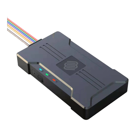
Figu e 1: Interface specifications of the FOX3-KMD device.
This confidential document is a property of FALCOM GmbH and may not be copied or circulated without previous permission.
Page 14 of 23
FOX3-KMD HARDWARE MANUAL VERSION 1.0.1
6.1. Main Po t (8pin connecto )
Figu e 2: Pin assignments of 8-pin (2x4) connector and installation cable connection (CA39 with 2A fuse).
6.1.1. Main Po t Pinout
PIN NAME DIRECTION DESCRIPTION LEVEL
1 +IN Input
Power supply input. The power supply must be
able to meet the requirements of current
consumption. For security reason, it is
recommended to integrate externally a 2A fuse link
between power source and FOX3-KMD.
V+IN = + 10.8 ... + 32.0 V
Imax ≤ 1.5 A
2 GND - Ground. 0 V
3 IGN Input
General purpose input. It can be either connected
to the vehicle ignition and be used for journey
STA T and STOP reports, or be connected to the
operating voltage +IN and be used to wakeup the
FOX3-KMD devices from IGN-Sleep mode (awaking
from this mode requires a HIGH signal).
HIGH ≥+10.8 .. +32.0 V DC; LOW = 0V
4 I/O1 Output Open collector digital output OUT: 100 mA max. @ +0 .. +32.0V DC
5 I/O2 CAN-LOW
6 I/O3 CAN-HIGH
7 xA_0 Input
(Se ial Po t 0) The serial port (receive data) for
direct connection to the host PC (for configuration,
evaluation, firmware). If this pin is not used leave it
open.
8 TxA_0 Output
(Se ial Po t 0) Serial port (transmit data) for direct
connection to the host PC (for transmitting history
data, output GPS protocols and more). If not used
leave it open.
V24, ±12 V
Table 5: Description of the main port (8-pin connector)
6.1.1.1. Se ial Po t 0 - Se ial communication signals (RxA and TxA)
FOX3-KMD devices incorporates a full duplex serial channel which allows two devices to communicate directly
with each other via the S232 serial port.
RxA_0 Main channel used to receive software commands to the board from any
software (e.g. HyperTerminal). Moreover, the firmware update can also be done
through this serial port.
TxA_0 Main channel used to output navigation, measurement, response and system
data to any software (e.g. HyperTerminal, FALCOM Workbench).
This confidential document is a property of FALCOM GmbH and may not be copied or circulated without previous permission.
Page 15 of 23
FOX3-KMD HARDWARE MANUAL VERSION 1.0.1
6.1.1.2. How to use I/O1 (pin 4)
This pin has dual functions. It is controlled by the internal firmware of FOX3-KMD. Therefore, the user must
define whether to use it as analog or digital pin. The configured digital pin can also be used as input or output
while the if configured as analog pin it can only be used as input.
The command PFAL,IO0.Config controlls its functionality.
$PFAL,IO0.Config=AI,2,11 // 0 = I/O1; AI = analog; 2 and 11 = min. and max. voltages for Low and High events
$PFAL,IO0.Config=DI,5,10 // 1= I/O2; DI = digital input; 5 and 10 = min. and max. voltages for Low and High events
If you want to use this pin as digital, then use one of the following PFAL command to trigger it to high or low:
$PFAL,IO4.Set=high //4= I/O1; high = sets output to high
$PFAL,IO4.Set=low //4 = I/O1; high = sets output to high
$PFAL,IO4.Set=cyclic,2000,1000 //4 = I/O1; cyclic = sets output to high for 2 seconds and low for 1 seconds.
The High and Low levels can be set with PFAL command (see above). When the internal firmware detects
changes on the analogue/digital input, then a Falling or Rising edge event is respectively triggered. This events
can be used to send alarms and messages to the server or via SMS.
As analogue input: connection example 1 (fo I/O1):
When used as analog input, e.g when connected to a temperature sensor (a NTC resistor for instance) use the
diagram below. The analog-to-digital converter (ADC) inside the device has an input voltage range from 0 to
2.5 V.
Figu e 3: Connection example 1 when using it as analog input and connected to an NTC (left) or Tachometer generator (right)
As digital input: connection example 1 (fo I/O1):
When used as digital input you can set VIN(LOW) and VIN(HIGH) to any levels within the range from +0 to +32.0
VDC.
Figu e 4: Connection example when using it as digital input.
This confidential document is a property of FALCOM GmbH and may not be copied or circulated without previous permission.
Page 16 of 23

FOX3-KMD HARDWARE MANUAL VERSION 1.0.1
As digital output: connection example 1 (fo I/O1):
When used as digital output you can connected via resistors ( ) directly to LEDs, elays etc., which do not
need more power than 100 mA @ up to + 32.0 V DC.
Figu e 5: Connection example 1 when using it to control a elay (left) or LED (right).
6.1.1.3. How to use IGN (pin 3)
It is strongly recommended to connect this pin to the ignition key to support the IGN-power saving function
when the vehicle is off. IGN-pin has two functions: 1) wakes up FOX3/-3G from IGN-sleep mode; 2) monitors
the vehicle ignition state, to report the trip STA T and STOP.
Figu e 6: Monitoring vehicle starter or use sleep modes by IGN line
6.1.1.4. How to connect and communicate with FOX3-KMD
To power on and communicate with FOX3-KMD device, you have to connect the power line to an external power
source ranging from 10.8 – 32VD and connect the serial port lines to your COM port on your PC as shown below.
Figu e 7: Set up your device for communication
This confidential document is a property of FALCOM GmbH and may not be copied or circulated without previous permission.
Page 17 of 23
FOX3-KMD HARDWARE MANUAL VERSION 1.0.1
6.2. NFC Windsc een (4pin connecto )
Figu e 8: Pin assignments of 4-pin (2x2) connector and NFC Windscreen connection
6.2.1. NFC Windsc een Po t Pinout
PIN NAME DIRECTION DESCRIPTION LEVEL
1 +IN Input Power supply input. V+IN = + 10.8 ... + 32.0 V
Imax ≤ 1.5 A
2 GND - Ground. 0 V
3 TX_NFC_1 Output Device Transmit channel to NFC Windscreen V24, ±12 V

4 X_NFC_1 Input Device eceive channel from NFC Windscreen V24, ±12 V
Table 6: Description of the NFC windscreen port (4-pin connector)
6.3. NFC InCa (4pin connecto )
Figu e 9: Pin assignments of 4-pin (2x2) connector and NFC InCar connection
6.3.1. NFC InCa Po t Pinout
PIN NAME DIRECTION DESCRIPTION LEVEL
1 +IN Input Power supply input. V+IN = + 10.8 ... + 32.0 V
Imax ≤ 1.5 A
2 GND - Ground. 0 V
3 TX_NFC_2 Output Transmit channel to NFC InCar V24, ±12 V
4 X_NFC_2 Input eceive channel from NFC InCar V24, ±12 V
Table 7: Description of the NFC InCar port (4-pin connector)
This confidential document is a property of FALCOM GmbH and may not be copied or circulated without previous permission.
Page 18 of 23

FOX3-KMD HARDWARE MANUAL VERSION 1.0.1
6.4. LED indicato s
The actual state of the FOX3-KMD can be shown by three LED’s on the front panel of the unit. These
programmable LEDs can be interfaced to show the status of the device.
Figu e 10: View of LED indicators
To turn on one of these LEDs, use the following command:
$PFAL,IO11.Set=high // 11=LED Orange;
$PFAL,IO12.Set=hpulse,2000 // 12=LED Green;
$PFAL,IO13.Set=cyclic,2000,1000 // 13=LED Red;
To turn off these LEDs, use the following command with corresponding index number:
$PFAL,IO[11,12,13].Set=low
6.5. Mounting
When installing a FOX3-KMD, there are two connectors on the device for connecting a GPS/GNSS antenna such
as FAL-ANT-11 (shown in figure below) or FAL-ANT-12 from FALCOM. During the installation, please make sure
the receiving side of the GSM/GPS antenna is up, with no metal object above or under the antenna and device
that interfere with GPS reception.
Each of FOX3-KMD device provide 8 holes to be attached to suitable locations (see figure below). It can be
mounted in different directions and different locations such as on wall or in vehicle. Fasteners can be Hexagon
head with collar self drilling screws DIN 7504 K, ST3.5 x 32(12) mm and different length. More detailed
information how to install the device in the vehicle, refer to the application note
"AppNotes_AVL_Installation_Guide.pdf".
FOX3-KMD are NOT waterproof or sealed devices. Care must be taken to ensure the devices are kept away from
water or any other liquids.
Figu e 11: View of the mounting holes
This confidential document is a property of FALCOM GmbH and may not be copied or circulated without previous permission.
Page 19 of 23

FOX3-KMD HARDWARE MANUAL VERSION 1.0.1
6.5.1. Exte nal Antenna Po ts
FOX3-KMD are fitted with two male SMB FAKRA connectors for connecting the FAL-ANT-14 GSM/3G/GNSS
antenna. Bo deaux connector connects to GSM/3G antenna cable and Blue connector connects to GNSS
antenna cable.
Figu e 12: GSM/3G/GPS antenna ports
CAUTION : Be careful not to accidental swap the GSM and GPS connectors. The device will not
function if the antennas are swapped. In order to comply with F exposure
requirements, install the antenna so that a distance minimum of 20 cm can be
maintained between the antenna and persons.
To connect the FAL-ANT-14 combined GSM/3G/GNSS antenna to the FOX3-KMD device:
✔Plug the Bo deaux connectors together and Blue connectors together.
To remove the FAL-ANT-14 GSM/3G/GNSS antenna from FOX3-KMD device:
✔Press down the latches on the antenna connectors and then pull the antennas.
Do not mount the antenna visible on the dashboard but mount it in a location underneath the dashboard. Hiding
the antenna is key to successful security in the event of theft. FOX3-KMD devices generate events in case of the
GNNS antenna is connected, disconnected or cut off. If an intruder cuts off the GNNS antenna cable, an event is
generated which can be used to trigger alarm notifications to the user.
This confidential document is a property of FALCOM GmbH and may not be copied or circulated without previous permission.
Page 20 of 23
Table of contents
Other FALCOM GPS manuals

FALCOM
FALCOM FSA03 User manual

FALCOM
FALCOM C2D-SI User manual

FALCOM
FALCOM BOLERO-LT User manual

FALCOM
FALCOM BOLERO-LT Guide

FALCOM
FALCOM DISCO-B4 User manual

FALCOM
FALCOM DISCO-B4-GLONASS User manual

FALCOM
FALCOM MAMBOII User manual

FALCOM
FALCOM MAMBO55 Guide

FALCOM
FALCOM NAVI-XS POI User manual

FALCOM
FALCOM DISCO-B5-MAGNET User manual

FALCOM
FALCOM NAVI-S User manual

FALCOM
FALCOM NAVI-1XT User manual

FALCOM
FALCOM NAVI-B-H User manual

FALCOM
FALCOM NAVI-XS User manual

FALCOM
FALCOM A2D-JP Operating and installation instructions

FALCOM
FALCOM MAMBO2-B6 User manual

FALCOM
FALCOM FOX3-2G Series User manual

FALCOM
FALCOM JP7-T Series Guide

FALCOM
FALCOM MAMBO2 User manual

FALCOM
FALCOM STEPP II User manual