FALCOM DISCO-B4-GLONASS User manual

THIS DOCUMENT IS AVAILABLE AT HTTP://WWW.FALCOM.DE/
.
DISCO-B4-GLONASS
Hardware manual
Version: 1.0.3 Modified: Tuesday 14 May 2013

DISCO-B4-GLONASS HARDWARE MANUAL VERSION 1.0.3
Table of contents
1 INTRODUCTION.................................................................................5
1.1 General......................................................................................................................5
1.2 Circuit concept.........................................................................................................6
1.3 Related documents..................................................................................................7
2 SECURITY.......................................................................................8
2.1 General information.................................................................................................8
2.2 Exposure to RF energ ............................................................................................8
2.3 Driving.......................................................................................................................8
2.4 Electronic devices....................................................................................................9
2.5 Vehicle electronic equipment.................................................................................9
2.6 Medical electronic equipment.................................................................................9
2.7 Aircraft.......................................................................................................................9
2.8 Children.....................................................................................................................9
2.9 Blasting areas...........................................................................................................9
2.10 Potentiall explosive atmospheres......................................................................9
3 SAFETY STANDARDS.......................................................................10
4 TECHNICAL DATA...........................................................................11
4.1 Product features.....................................................................................................11
4.1.1 Power consumption............................................................................................12
4.1.2 Operating temperatures......................................................................................13
4.1.3 GSM/GPRS engine features..............................................................................14
4.1.4 Navigation features.............................................................................................15
4.2 NMEA data message..............................................................................................16
5 DISCO-B4-GLONASS APPLICATION INTERFACE..............................17
5.1 Power suppl ..........................................................................................................17
5.1.1 Power supp y pins (1 and 2) on the 8-pin connector..........................................17
5.1.2 Automatic shutdown...........................................................................................17
5.1.3 Power saving......................................................................................................18
5.2 Determining the External Equipment T pe.........................................................18
6 HARDWARE INTERFACES..................................................................1
6.1 8pin connector, pin assignments.........................................................................20
6.1.1 8-pin connector pinout........................................................................................20
6.1.2 Specia pin description (Pins 4, 5, 6)..................................................................21
6.1.2.1 How to use them as analog inputs.........................................................................................21
6.1.2.2 How to use these pins as digital Inputs (Pin 4, 5, 6)..............................................................23
6.1.2.3 How to use these pins as digital outputs (Pin 4, 5, 6)............................................................24
6.1.2.4 How to use IGN pin(pin 3)......................................................................................................25
6.1.2.5 erial communication signals (RxA and TxA)........................................................................26
6.1.3 4pin row connector.............................................................................................26
6.2 Insert the SIM card holder inside the device.......................................................27
6.2.1 How to enter the SIM card PIN:..........................................................................29
This confidential document is a property of FALCOM and may not be copied or circulated without previous permission.
Page 2 of 36

DISCO-B4-GLONASS HARDWARE MANUAL VERSION 1.0.3
6.3 Mounting.................................................................................................................29
6.4 Audio jacks.............................................................................................................30
6.4.1.1 Audio Interface .....................................................................................................................31
7 HOUSING.....................................................................................32
8 APPENDIX....................................................................................33
8.1 Schematics.............................................................................................................33
8.1.1 Insta ation guidance for 8-pin connector............................................................33
8.2 Setting up DISCO-B4-GLONASS-EVALKIT..........................................................34
8.3 What should be considered when using the DISCO-B4-GLONASS device.....35
Version history:
This table provides a summary of the document revisions.
Version Author Changes Modi ied
.0.3 F. Beqiri - Added "Hint:" - An annual replacement of the O'ring rubber recommended.
- Added chapter 6.2. - Procedure for greasing the O-ring.
4/05/20 3
.0.2 F. Beqiri - Added the part number of 8pin connector (Neltron 5560A-08) - Counter part (Neltron 5560T-08)
- Added the part number of 4pin connector (Neltron 556 A-04) - Counter part (Neltron 5560A-04)
- Updated chapter 8. .
04/09/20 2
.0. F. Beqiri - Changed device name from FOX-LT-IP-GLONASS to DISCO-B4-GLONASS 7/ 0/20
.0.0 F. Beqiri - Initial version. 3 /03/20
This confidential document is a property of FALCOM and may not be copied or circulated without previous permission.
Page 3 of 36

DISCO-B4-GLONASS HARDWARE MANUAL VERSION 1.0.3
Cautions
Information furnished herein by FALCOM is believed to be accurate and reliable. However, no
responsibility is assumed for its use. Please, read carefully the safety precautions.
If you have any technical questions regarding this document or the product described in it, please
contact your vendor.
General information about FALCOM and its range of products are available at the following Internet
address: http://www.falcom.de/
Trademarks
Some mentioned products are registered trademarks of their respective companies.
Copyright
This document is copyrighted by FALCOM WIRELESS COMMUNICATIONS GmbH with all rights reserved. No
part of this documentation may be produced in any form without the prior written permission of FALCOM
WIRELESS COMMUNICATIONS GmbH.
FALCOM WIRELESS COMMUNICATIONS GmbH.
No patent liability is assumed with respect to the use of the information contained herein.
Note
Specifications and information given in this document are subject to change by FALCOM without
notice.
This confidential document is a property of FALCOM and may not be copied or circulated without previous permission.
Page 4 of 36

DISCO-B4-GLONASS HARDWARE MANUAL VERSION 1.0.3
1 INTRODUCTION
This product manual is only addressed to qualified personnel which are well skilled in
electronical/electrical installation and not addressed to private consumers / end users. The
installation, implementing or setting into operation of the product can only be performed by
qualified personnel.
The status of the product described in the data sheet may have changed since publication of the
data sheet and therefore information in this data sheet on product status may be outdated. The
latest information of the product is available on the download area of the FALCOM website.
1.1 General
FALCOM is providing all kinds of GPS and telematics products as required by the market today.
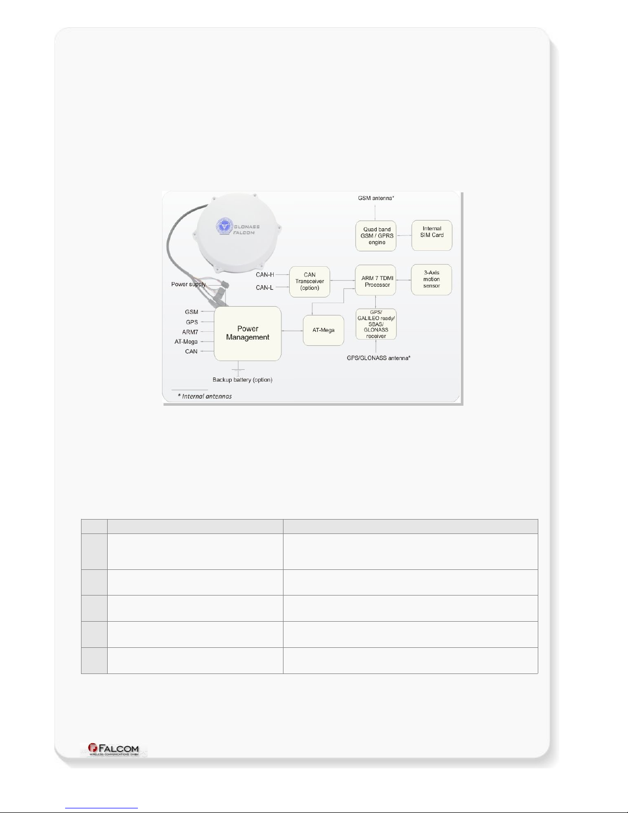
DISCO-B4-GLONASS unit is a new vehicle tracking system combining GPS and GLONASS positioning
systems with a higher level of reliability for complete telematics functionality. It is a free
configurable smart tracking device which can be fully adapted to user requirements. Using a Quad-
Band GSM/GPRS technology for two way worldwide communication, the ability to work with
global navigation satellite systems (GNSS) - GPS and GLONASS, a high-capacity Li-Polymer
rechargeable backup-battery, and housed in a weatherproof plastic case, the device is suitable for
a wide range of mixed indoor/outdoor applications in the AVL, fleet management, Asset tracking,
vehicle security and recovery and transit sectors. The device has a protection class IP69K, which
allows mounting of the device permanently on the roof of the vehicles, including buses, trucks,
trains, vessels and other assets. The DISCO-B4-G ONASS device comprises an embedded
configurable software that provides even greater performance and flexibility for its users and
system integrators to develop high-performance applications that allow vehicle tracking via SMS
and over the Internet. The configuration of the DISCO-B4-G ONASS can be done via local serial link
or remotely via SMS or over the Internet. The tracking functionality of the embedded mobile client
application is combined with a variety of alert messaging capabilities. The configurable alert
messages may contain current position, device status and the state of the inputs/outputs lines. In
addition to that two predefined digital inputs are detecting ignition line status and main power (car
battery) failure, so you may handle these events and use as notification.
The embedded software can be controlled by word like “PFAL” commands needed for executing
particular actions, reading or setting particular configurations. These commands are valid for all
kinds of operation channels including Serial, SMS, CSD, TCP and SMTP.
DISCO-B4-GLONASS provides Geofence features for territory management, route verification,
prohibited locations, parking area and more, with exception reporting to a wide variety of events
such as arrivals, departures, deliveries, pick-ups, illegal entries, unauthorized movement, etc.
DISCO-B4-G ONASS contains a data-logger (history feature) that enables you to archive unique
vehicle locations in sequence for up to 45 days for later analysis and evaluation (for example,
archive interval up to 20 sec.).
The physical interface to the device application is made through an integrated 8pin connector. It is
required for controlling the device, receiving GPS location data, transferring data and providing
automotive power supply lines. This connector provides serial interface giving you maximum
flexibility for local use. A separate 4pin double row connector (containing RX, TX, GND and VOUT) is
for connecting a MFD device and two separate audio jacks for directly connecting an active speaker
and a microphone.
This confidential document is a property of FALCOM and may not be copied or circulated without previous permission.
Page 5 of 36

DISCO-B4-GLONASS HARDWARE MANUAL VERSION 1.0.3
DISCO-B4-G ONASS is a device that can be configured and integrated onto any asset platform, including:
-Trailers,
-Trucks,
-Delivery vans,
-Ships,
- Trains,
-Rail cars,
-as well as other industrial monitoring solutions.
and it can be used in a variety of applications, including:
•Real time online tracking,
•Asset Tracking,
•Fleet management / monitoring,
•Security / emergency services,
•Real time satellite navigation,
•Territory management,
•Personalized drivers logbook,
•Route verification,
•Trip management / distance calculations,
•Theft protection,
•Toll collection,
•Pay as you drive.
1.2 Circuit concept
DISCO-B4-G ONASS architecture consists of the following major components (a block diagram is
available below):
HARDWARE ARCHITECTURE:
High-performance Quad-Band GSM/GPRS core,
Combined GPS/GA I EO ready/G ONASS/SBAS receiver for precise positioning,
ARM7TDMI Processor controlling all functions of the system,
Internal GSM antenna,
Internal GPS/G ONASS antenna.
ADDITIONAL OPTIONS TO DISCO-B4-GLONASS
D motion sensor,
Rechargeable i-Polymer battery (see Ordering Guide).
CAN-BUS interface
This confidential document is a property of FALCOM and may not be copied or circulated without previous permission.
Page 6 of 36

DISCO-B4-GLONASS HARDWARE MANUAL VERSION 1.0.3
PHYSICAL INTERFACES:
8pin double row connector
Power supply lines,
3 x Multi-line I/Os,
1 x Ignition,
RS232 port (Rx, Tx, GND),
Audio jacks for voice call (1 x Microphone; 1 x Speaker),
Figure 1: DISCO-B4-GLONASS block diagram
1.3 Related documents
Some other PDF documents such as FCC approval, application notes, Certificate of Conformity
R&TTE etc. are also available on the Web at: http://www.falcom.de/ in the published download
area. In addition to this document, the following files comprise the full set of FALCOM DISCO-B4-
G ONASS product manuals:
NR PDF ile name Description
[ ] AVL_PFAL_Configuration_Command_Set.pdf Contains the description of the internal firmware and the supported
Configuration Command Set for the FALCOM STEPPIII, FOX/-LT/-EN/-IN,
DISCO and BOLERO-LT.
[2] AppNotes_Transform_history_data.pdf Contains information of how to transform history data that is being
transmitted from a FALCOM AVL device via TCP connection.
[3] AppNote_Remote_update.pdf Contains information of how to upgrade FALCOM AVL devices to a new
firmware revision remotely via TCP (server based application).
[4] STEPPIII_FOX_BOLERO_LT_Software_Update.pdf Contains information how to upgrade a FALCOM AVL device to a new
firmware version locally via serial port.
[5] AppNotesRemoteUpdateWithWorkbench.pdf Contains information how to upgrade a FALCOM AVL devices to a new
firmware version remotely via TCP.
These PDF files are viewable and printable from Adobe Reader. If you do not have the Adobe Reader installed, you can
download it from http://www.adobe.com.
This confidential document is a property of FALCOM and may not be copied or circulated without previous permission.
Page 7 of 36

DISCO-B4-GLONASS HARDWARE MANUAL VERSION 1.0.3
2 SECURITY
IMPORTANT FOR THE EFFICIENT AND SAFE OPERATION OF YOUR GSM-MODEM, READ THIS
INFORMATION BEFORE USE!
Your cellular engine DISCO-B4-G ONASS is one of the most exciting and innovative electronic
products ever developed. With it you can stay in contact with your office, your home, emergency
services and others, wherever service is provided.
This chapter contains important information for the safe and reliable use of the DISCO-B4-
G ONASS device. Please read this chapter carefully before starting to use the cellular engine
DISCO-B4-G ONASS.
2.1 General in ormation
Your DISCO-B4-G ONASS device utilizes the GSM/GPS standard for cellular technology. GSM is a
newer radio frequency („RF“) technology than the current FM technology that has been used for
radio communications for decades. The GSM standard has been established for use in the
European community and elsewhere. Your DISCO-B4-G ONASS is actually a low power radio
transmitter and receiver. It sends out and receives radio frequency energy. When you use your
modem, the cellular system handling your calls controls both the radio frequency and the power
level of your cellular modem.
SIM cards are needed for the use of the acquired devices, which are not included in the scope of
delivery of the device. The SIM cards can be acquired e.g. by specific providers. Additional costs can
result from the use of the SIM cards which are to be borne by the purchaser (client) of the devices.
The seller does not cover the extra costs for the use of the devices. The seller gives no
recommendation for the use of specific SIM cards and is not liable for the fact that the devices are
usable with all available SIM cards. The seller is also not liable for any other costs that are needed
for the application of the customer in connection with this device.
2.2 Exposure to RF energy
There has been some public concern about possible health effects when using GSM modems.
Although research on health effects from RF energy has focused for many years on the current RF
technology, scientists have begun research regarding newer radio technologies, such as GSM. After
existing research had been reviewed, and after compliance to all applicable safety standards had
been tested, it has been concluded that the product is fit for use.
If you are concerned about exposure to RF energy, there are things you can do to minimize
exposure. Obviously, limiting the duration of your calls will reduce your exposure to RF energy. In
addition, you can reduce RF exposure by operating your cellular modem efficiently by following the
guidelines below.
2.3 Driving
Check the laws and regulations on the use of cellular devices in the area where you drive. Always
obey them. Also, when using your DISCO-B4-G ONASS while driving, please pay full attention to
driving, pull off the road and park before making or answering a call if driving conditions so require.
When applications are prepared for mobile use, they should fulfil road-safety instructions of the
current law!
This confidential document is a property of FALCOM and may not be copied or circulated without previous permission.
Page 8 of 36

DISCO-B4-GLONASS HARDWARE MANUAL VERSION 1.0.3
2.4 Electronic devices
Most electronic equipment, for example in hospitals and motor vehicles is shielded from RF
energy. However, RF energy may affect some malfunctioning or improperly shielded electronic
equipment.
2.5 Vehicle electronic equipment
Check your vehicle manufacturer’s representative to determine if any on board electronic
equipment is adequately shielded from RF energy.
2.6 Medical electronic equipment
Consult the manufacturer of any personal medical devices (such as pacemakers, hearing aids, etc.)
to determine if they are adequately shielded from external RF energy.
Turn your DISCO-B4-G ONASS device OFF in health care facilities when any regulations posted in
the area instruct you to do so. Hospitals or health care facilities may be using RF monitoring
equipment.
2.7 Aircra t
Turn your DISCO-B4-G ONASS OFF before boarding any aircraft. Use it on the ground only with
crew permission. Do not use it in the air. To prevent possible interference with aircraft systems,
Federal Aviation Administration (FAA) regulations require you to have permission from a crew-
member to use your modem while the plane is on the ground. To prevent interference with cellular
systems, local RF regulations prohibit using your modem whilst airborne.
2.8 Children
Do not allow children to play with your DISCO-B4-G ONASS device. It is not a toy. Children could
hurt themselves or others (by poking themselves or others in the eye with the antenna, for
example). Children could damage the modem or make calls that increase your modem bills.
2.9 Blasting areas
To avoid interfering with blasting operations, turn your device OFF when in a “blasting area” or in
areas posted: „turn off two-way radio“. Construction crew often uses remote control RF devices to
set off explosives.
2.10 Potentially explosive atmospheres
Turn your DISCO-B4-GLONASS device OFF when in any area with a potentially explosive
atmosphere. It is rare, but your modems or their accessories could generate sparks. Sparks in such
areas could cause an explosion or fire resulting in bodily injury or even death. Areas with a
potentially explosive atmosphere are often, but not always, clearly marked. They include fuelling
areas such as petrol stations; below decks on boats; fuel or chemical transfer or storage facilities;
and areas where the air contains chemicals or particles, such as grain, dust or metal powders. Do
not transport or store flammable gas, liquid or explosives, in the compartment of your vehicle,
which contains your modem or accessories.
Before using your modem in a vehicle powered by liquefied petroleum gas (such as propane or
butane) ensure that the vehicle complies with the relevant fire and safety regulations of the
country in which the vehicle is to be used.
This confidential document is a property of FALCOM and may not be copied or circulated without previous permission.
Page 9 of 36

DISCO-B4-GLONASS HARDWARE MANUAL VERSION 1.0.3
3 SAFETY STANDARDS
Your GSM/GPRS/GPS device complies with all applicable RF safety standards.
DISCO-B4-G ONASS meets the safety standards for RF receivers and the standards and
recommendations for the protection of public exposure to RF electromagnetic energy established
by government bodies and professional organizations, such as directives of the European
Community, Directorate General V in matters of radio frequency electromagnetic energy.
This confidential document is a property of FALCOM and may not be copied or circulated without previous permission.
Page 10 of 36

DISCO-B4-GLONASS HARDWARE MANUAL VERSION 1.0.3
4 TECHNICAL DATA
4.1 Product eatures
Supply voltage range:
➢Operating power supply voltage range of +10.8 V to +32.0 V,
suitable for direct connection to an automotive +12V or +24V DC
power source (car battery).
Power saving:
➢7 different energy-saving modes - programmable with PFA
commands. Refer to the chapter 5.1.3, "Power saving" for a brief
overview.
Operating temperature range:
➢- 40°C to + 85°C (see chapter 4.1.2 for more details)
Physical characteristics:
➢Size: Ø 187.2 ± 0.1 mm; ↕ 47.2 ± 0.1 mm
➢Weight (without options): ca. 468 gr.
Physical Interfaces:
➢8-pin single row connector (Neltron 5560A-08):
✔3 x I/Os multi functional (each pin has dual functions as analog or
digital - software configurable. Each digital pin can operate either
as an input or output - depending on the external user-circuit),
✔1 x Ignition (software controlled feature),
✔1 x Power supply (software controlled feature)
✔1 x Serial port (Rx, Tx), Baud rate is controlled by firmware
4800...115200 bps (default=57600 bps), 8 data bits, no parity, 1
stop bit, no flow control,
➢4-pin single row connector (Neltron 5561A-04):
✔1 x Power (output voltage for external devices such as MFD1)
✔1 x Serial port (Rx, Tx 3.3V levels), Baud rate is controlled by
firmware 4800...115200 bps (default=57600 bps), 8 data bits, no
parity, 1 stop bit, no flow control,
➢Audio jacks:
✔1 x Microphone (2.5mm jack),
✔1 x Speaker (3.5mm jack),
➢Internal SIM Card holder (supports 1.8/3 V SIM cards) - SIM card
should be inserted by skilled personnel.
Housing:
➢PA6 Plastic.
➢Protection class: IP69K
This confidential document is a property of FALCOM and may not be copied or circulated without previous permission.
Page 11 of 36

DISCO-B4-GLONASS HARDWARE MANUAL VERSION 1.0.3
Directive:
➢RoHS compliant.
Firmware:
➢Embedded TCP/IP stack, including TCP, IP and SMTP protocols,
➢Accessible via PFA commands,
➢Upgradable locally via serial port and remotely over the air
(GPRS/TCP).
Internal memory:
➢8 Mbyte F ASH for configuration, data-logging and firmware storage,
➢2 MByte RAM.
Evaluation board:
➢To evaluate with DISCO-B4-G ONASS you need a FOX evaluation
board which is included in the DISCO-B4-G ONASS EVA KIT (see
chapter 8.2).
Supported protocols:
➢NMEA Msg.: GLL, GGA, RMC, VTG, GSV, GSA
FA COM Msg.: IOP, GSM, AREA, DP, BIN - see related
documents [1] and Table 3.
4.1.1 Power consumption
All measurements have been performed: DCS 1800 MHz, Power evel 10, Cell Power -75dBm, Tamb=
23°C, VIN+ = 12 V DC and 4.2 V DC (battery powered).
Modes Average power
consumption (mA) @ +12 V
Average power
consumption (mA) @ +4.2 V
Comments
GPS off / GSM off
GPS on / GSM off
GPS off / GSM on
GPS on / GSM on
58 85 Microcontroller remains on
85 144 with valid GP -fix
70 112 G M idle (registered) and GP R detached
100 170 GPR is attached and TCP-connected.
Device sends a TCP packet every 30 sec.
Note: These values may vary over time and environments condition can not be guaranteed.
Table 1: Power supp y and current consumption at 12 VDC
Average current consumption in sleep mode
Sleep Modes @ 12 V (external power) @ 4 V (battery power) Unit
IGN 840 260 µA
IGN+Motion 1230 810 µA
IGN+Ring 17 22 mA
IGN+Timer 920 330 µA
Note: These values may vary over time and environments condition can not be guaranteed.
Table 1.1: Power supply and current consumption for different sleep modes.
This confidential document is a property of FALCOM and may not be copied or circulated without previous permission.
Page 12 of 36

DISCO-B4-GLONASS HARDWARE MANUAL VERSION 1.0.3
4.1.2 Operating temperatures
Parameter Min. Typ. Max. Unit
Storage temperature (without internal battery) -40 +25 +90 °C
Storage temperature (with internal battery) -20 +25 +60 °C
Operating temperature* (without internal battery) -40 +25 +85 °C
Charging temperature 0 +25 +45 °C
Discharging temperature -20 +25 +60 °C
* The GSM/GPRS module is fully functional (-20 °C to + 55 °C meets the 3GPP specifications)
Table 2: Operating temperature
This confidential document is a property of FALCOM and may not be copied or circulated without previous permission.
Page 13 of 36

DISCO-B4-GLONASS HARDWARE MANUAL VERSION 1.0.3
4.1.3 GSM/GPRS engine eatures
GSM/GPRS core:
➢Quad-Band GSM/GPRS module
➢Quad-Band: GSM 850, 900, DCS 1800, PCS 1900.
➢Compliant to GSM Phase 2/2+
Output power:
➢Class 4 (2 W) at EGSM900/850
➢Class 1 (1 W) at GSM1800 and GSM 1900
GPRS connectivity:
➢GPRS multi-slot class 10
➢GPRS mobile station class B
DATA:
GPRS
➢GPRS data downlink transfer: max. 85.6 kbps (see table 2).
➢GPRS data uplink transfer: max. 42.8 kbps (see table 2).
➢Coding scheme: CS-1, CS-2, CS-3 and CS-4.
CSD
➢CSD transmission rates: 2.4, 4.8, 9.6, 14.4 kbps, non-transparent,
V.110.
SMS:
➢Text mode.
Ring tones:
➢Offers a choice of 30 different ringing tones, easily selectable with
PFA commands.
GPRS Coding scheme:
Coding scheme 1 Timeslot 2 Timeslots 4 Timeslots
CS- : 9.05 kbps 8. kbps 36.2 kbps
CS-2: 3.4 kbps 26.8 kbps 53.6 kbps
CS-3: 5.6 kbps 3 .2 kbps 62.4 kbps
CS-4: 2 .4 kbps 42.8 kbps 85.6 kbps
Table 2: Coding schemes and maximum net data rates over air interface
Please note that, the values listed above are the maximum ratings which, in practice, are influenced by a great
variety of factors, primarily, for example, traffic variations and network coverage.
This confidential document is a property of FALCOM and may not be copied or circulated without previous permission.
Page 14 of 36

DISCO-B4-GLONASS HARDWARE MANUAL VERSION 1.0.3
4.1.4 Navigation eatures
GPS/GLONASS/GALILEO ready/SBAS engine:
➢Number of channels: 32
➢GPS/GA I EO ready/SBAS: 1 1575.42 MHz
➢G ONASS: 1 1597.5 - 1609.5 MHz
Accuracy:
➢horizontal
✔autonomous mode 2.5 m
✔differencial mode 1 m
➢height 3 m
➢velocities 0.05 m/s
Time to First Fix (TTFF):
➢Hot starts < 3 s
➢Cold starts 30 s
Sensitivity:
➢Tracking -160 dBm
➢Acquisition -143 dBm
Dynamic Conditions:
➢Velocity 500 m/s.
➢Acceleration 5 g
➢Altitude 18 000 m
➢Max. update rate 1 Hz
This confidential document is a property of FALCOM and may not be copied or circulated without previous permission.
Page 15 of 36

DISCO-B4-GLONASS HARDWARE MANUAL VERSION 1.0.3
4.2 NMEA data message
DISCO-B4-GLONASS delivers data in the NMEA-0 83 format. Table below lists the NMEA and
FALCOM output messages supported by the DISCO-B4-GLONASS device and gives a brief
description for each protocol. For further description about these protocols, refer to the related
documents [ ].
The running firmware inside the device offers the possibility to switch on and off each protocol
that is listed in the table below. As mentioned above the firmware inside the device supports a lot
of PFAL commands enabling full control of the device. There are also PFAL commands which allow
sending of these protocols via SMS, TCP, Data call and e-mail. For example, the PFAL commands
"PFAL,GSM.SMS.Send..." and "PFAL,TCP.Client.Send..." allow you to send an SMS message to a
user or a TCP packet to a TCP server to let him know the current location, GPS state, UTC time,
Date, Speed and Course over ground of the device. The received SMS contents or TCP packet can
be forwarded to a map software for locating the device graphically on it. When you install such a
device in a vehicle, you are able to have always full control of the vehicle. In this way you will know
where your vehicle is, what is happening with your vehicle, has your vehicle been moved without
authorization from a park area, real time vehicle movements and more. The TCP server developed
by FALCOM called "Trace4You" has a lot of such features allowing you to have full control of your
vehicle, fleet and other assets.
NMEA Description
GGA Time, position and fix type data.
GLL Latitude, longitude, UTC time of position fix and status.
GSA GPS receiver operating mode, satellites used in the position solution and DOP values.
VTG The direction and the ground speed
GSV The number of GPS satellites in view, satellite ID numbers, elevation, azimuth and SNR values.
RMC Time, date, position, course and speed data.
FALCOM Description
IOP The status of the digital/analog inputs and output ports and battery voltage (if battery available)
GSM The GSM operator, reception, registration status, GSM field strength, area code and cell ID.
AREA The state (entered / remaining) of 32 areas/geofences - such as territory management, route verification,
prohibited locations, parking area and more.
3DP The state of the Motion Sensor (hardware option)
BIN User protocol including time, date, position, course and speed data in binary format (small sized - only 21
characters).
Table 3: NMEA Output Messages
This confidential document is a property of FALCOM and may not be copied or circulated without previous permission.
Page 16 of 36

DISCO-B4-GLONASS HARDWARE MANUAL VERSION 1.0.3
5 DISCO-B4-GLONASS APPLICATION INTERFACE
5.1 Power supply
The power supply for the DISCO-B4-GLONASS unit has to be a single voltage source of V+IN = +10.8
V...+32.0 VDC. The operating voltage (V+IN) has to be permanently applied to the DISCO-B4-
G ONASS unit and able to provide sufficient current of up to 1.9 A.
The operating voltage (V+IN and GND) is protected against voltage spikes and reverse polarity, but not
against continuous-overvoltage.
NOTE: Operating voltage range must never be exceeded; care must be taken in order to fulfill
min/max voltage requirements.
5.1.1 Power supply pins (1 and 2) on the 8-pin connector
One +IN pin on the 8-pin double row connector is dedicated to connect the supply voltage, and the
GND pin for grounding.
Both +IN and GND pins serve for powering the DISCO-B4-GLONASS device and charging the
internal Li-Polymer battery if available (option). DISCO-B4-G ONASS has an automatic power
ON-function when external power is applied. The power supply for the DISCO-B4-GLONASS is
capable of utilizing current ranging from V+IN=+10.8 V... +32.0 VDC designed for automotive
application.
Signal name I/O Parameter Description
+IN I+10.8 V...+32.0 VDC. The
operating voltage must never be
exceeded.
Positive operating voltage.
For security reason, it is recommended to integrate externally
a 2A fuse link between interconnection plug (8-pin connector)
and d.c.-power source (see Fig. 16).
GND - 0 V Ground
5.1.2 Automatic shutdown
Automatic shutdown takes effect if:
•battery voltage level runs low and external power supply is disconnected.
•supply voltage is below the specified input voltage range and internal battery is
disabled.
This confidential document is a property of FALCOM and may not be copied or circulated without previous permission.
Page 17 of 36

DISCO-B4-GLONASS HARDWARE MANUAL VERSION 1.0.3
5.1.3 Power saving
SLEEP mode reduces the functionality of the modules of the DISCO-B4-G ONASS device to a
minimum and thus minimizes the current consumption to the lowest level. Settings for activating
one of the supported low power modes can be made using the $PFAL,Sys.Device.Sleep command.
For details, see example in table below.
Following S EEP modes are supported by the DISCO-B4-G ONASS device:
Modes Description
IGN Device goes to sleep and wakes up when IGN (pin 3 - blue color) changes its digital level from
ow to High (performs a rising edge).
Ring Device goes to sleep and wakes up when the GSM module receives a voice call or an SMS.
Timer=1:20:00 Device goes to sleep and wakes up after the defined time has expired.
Motion=5,20,20 Device goes to sleep and wakes up when motion is detected.
ExtPwrDetect Device goes to sleep and wakes up when external power (higher than 9 V) is connected to the
device.
ExtPwrDrop Device goes to sleep and wakes up when external power is disconnected or it drops below 8 V.
AiWu=5.1,12 Device goes to sleep and wakes up when the voltage on I/O1 (pin 4 used as analog input)
exceeds the defined upper or lower threshold.
Example $PFAL,Sys.Device.Sleep=IGN+Ring+Timer=1:20:00
IMPORTANT: The sleep and wake-up procedures are quite different depending on the selected
sleep mode. Please keep in mind that the power saving with "Ring" parameter
works properly only when PIN authentication has been done and the device is
already registered in the GSM network. If you attempt to activate power saving
while the device is not registered in the GSM network, the SIM card is not inserted
or the PIN not correctly entered, the device responds with an error "ring shutdown
aborted due to bad GSM coverage" and the power saving does not take place. For
more details, refer to the manual "steppIII_FOX-
LT_bolero_lt_PFAL_Configuration_Command_Set.pdf".
NOTE (This note is related to the battery-powered devices only): The internal battery of the DISCO-
B4-GLONASS must have enough power to safely wake up the device from a sleep mode. If the
internal battery of the DISCO-B4-GLONASS device does not have enough power, the device
cannot complete the wake up operation.
5.2 Determining the External Equipment Type
Before you connect the serial port pins on the aforementioned terminals (DCE units) to external
equipment, you need to determine if the external hardware serial ports are configured as DTE or
DCE.
DISCO-B4-GLONASS is designed for use as a DCE device. Based on the aforementioned conventions
for DCE-DTE connections, it communicates with the customer application (DTE) using the following
signals:
DISCO-B4-GLONASS Terminal (DCE) to Application (DTE)
RxA <---------- TXD
TxA ----------> RXD
Table 4: The signalling definitions between DTE and DCE.
This confidential document is a property of FALCOM and may not be copied or circulated without previous permission.
Page 18 of 36

DISCO-B4-GLONASS HARDWARE MANUAL VERSION 1.0.3
6 HARDWARE INTERFACES
This chapter describes the hardware interfaces:
•8pin single row connector (Neltron 5560A-08)
•Mounting holes
•Audio jacks (3.5mm and 2.5mm audio jacks)
•4pin single row connector (Neltron 5561A-04)
Inter ace speci ications
8pin single row connector Eight-wire cable with an 8-pin connector (Neltron 5560A-08) on the end and 1
meter cable length. It consists of IN/OUT, power supply line and RX/TX.
Audio jacks 3.5mm and 2.5mm audio jacks. The 3.5mm jack is where you plug in a speaker.
The 2.5mm jack is where you plug in a microphone.
Mounting holes 6 holes for attaching it to a suitable location (use M4x30 self tapping or machine
screws, not included).
Fastening screw holes 12 x holes for fastening both cases together.
4pin single row connector Four-wire cable with an 4-pin connector (Neltron 5561A-04) on the end and 1
meter cable length for connecting a MFD device to the DISCO-B4-G ONASS.
Table 5: Interface specifications
Figure 2: Interface specifications
This confidential document is a property of FALCOM and may not be copied or circulated without previous permission.
Page 19 of 36

DISCO-B4-GLONASS HARDWARE MANUAL VERSION 1.0.3
6.1 8pin connector, pin assignments (Neltron 5560A-08)
Figure 3: Pin assignments of the 8-pin connector.
6.1.1 8-pin connector pinout
PIN NAME COLOR DIRECTION DISCRIPTION LEVEL
+IN Red Input
Power supply input. The power supply must be able to
meet the requirements of current consumption. Care
must be taken so that the operating voltage applied to
the terminal stays within the voltage range. Applying a
voltage outside of the voltage range can damage the
module. For security reason, it is recommended to
integrate externally a 2A fuse link between power
source and DISCO-B4-GLONASS.
V+IN = + 0.8 ... + 32.0 V
Imax ≤ 2A
2 GND Braun - Ground. 0 V
3 IGN Blue Input
General purpose input. Either connect it to the vehicle
ignition and use it for journey START and STOP reports
or connect it to the operating voltage +IN and with the
help of an external switch you wakeup the DISCO-B4-
GLONASS device from IGN-Sleep mode (awaking from
this mode requires a HIGH signal). See also chapter
6. .2.4.
HIGH ≥+ 0.8 .. +32.0 V DC;
LOW = 0V
4 I/O Orange
5I/O2 or
CAN_L Yellow
6I/O3 or
CAN_H Green
Input/Output
Software configurable pins. Each pin has dual functions
as analog or digital. Each digital pin can be individually
set to operate either as input or output.
OUT: 00 mA max. @ +0 ..
+32.0V DC
IN: 0 V..+32.0V DC
(High & Low levels are free-
programmable)
Analog : Up to 32.0 V DC/ 0
bits resolution
7 RxA Purple Input
Serial port (receive data) for direct connection to the
host PC (configuration, evaluation, firmware). If not
used leave open.
V24, ±2 V
8 TxA Black Output
Serial port (transmit data) for direct connection to the
host PC (transmitting history data, output GPS protocols
and others). If not used leave open.
V24, ±2 V
Table 6: Description of the 8-pin double-row connector
This confidential document is a property of FALCOM and may not be copied or circulated without previous permission.
Page 20 of 36
Table of contents
Other FALCOM GPS manuals

FALCOM
FALCOM MAMBOII User manual

FALCOM
FALCOM FOX3-2G Series User manual

FALCOM
FALCOM JP7-T Series Guide

FALCOM
FALCOM FSA03 User manual

FALCOM
FALCOM NAVI-B-H User manual

FALCOM
FALCOM DISCO-B4 User manual

FALCOM
FALCOM JP14-R-LP User manual

FALCOM
FALCOM STEPP II User manual

FALCOM
FALCOM MAMBO2-B6 User manual

FALCOM
FALCOM NAVI-1XT User manual

FALCOM
FALCOM C2D-SI User manual

FALCOM
FALCOM BOLERO-LT User manual

FALCOM
FALCOM NAVI-XS User manual

FALCOM
FALCOM MAMBO2-B6 User manual

FALCOM
FALCOM MAMBO2 User manual

FALCOM
FALCOM NAVI-S User manual

FALCOM
FALCOM BOLERO-LT Guide

FALCOM
FALCOM A2D-JP Operating and installation instructions

FALCOM
FALCOM DISCO-B5-MAGNET User manual

FALCOM
FALCOM NAVI-XS POI User manual