Falcon FN2 Series Instruction Manual

Revision: C
P/N: OM480053
Falcon Electric, Inc.
FN2 Series
Uninterruptible Power Supply
Installation & User Manual
© 2020 Falcon® Electric, Inc. All rights reserved. Falcon® and the Falcon Electric logo are registered trademarks of Falcon Electric, Inc.
All other brand names and trademarks are the property of their respective owners. The information and specifications stated in this document are
subject to change without notice. 4-2020
www.falconups.com
Rackmount Models
FN2-6KRM-2TXI
FN2-8KRM-2TXI
FN2-10KRM-2TXI


Installation & User Manual Falcon Electric, Inc.
FN2 Series OM480053 Rev.: C3
Contents
Safety............................................................................................................................................5
Retain This User Manual...........................................................................................................5
Warnings ...................................................................................................................................5
Transportation ...........................................................................................................................7
Storage......................................................................................................................................7
Operating Conditions.................................................................................................................8
Introduction ...................................................................................................................................9
Overview ...................................................................................................................................9
UPS Features............................................................................................................................9
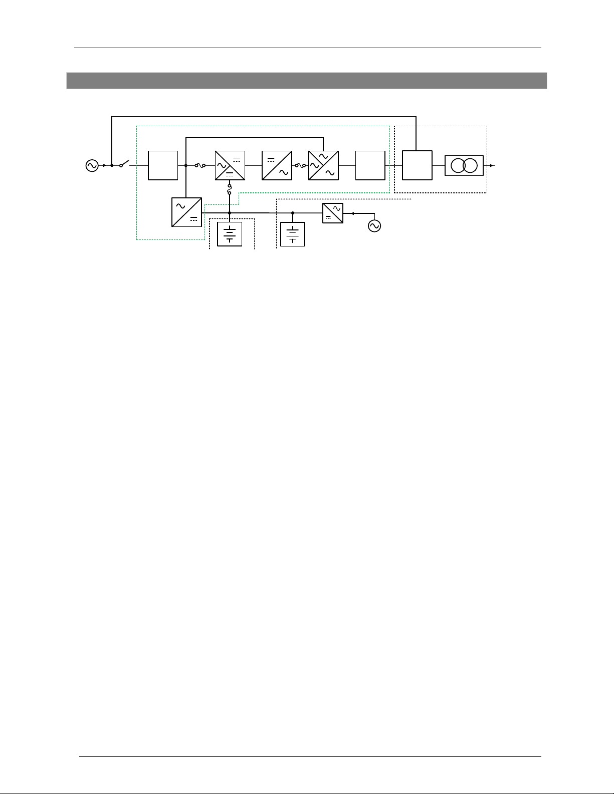
UPS Block Diagram.................................................................................................................10
Product Overview........................................................................................................................11
Inspecting the Equipment........................................................................................................11
Box Contents...........................................................................................................................11
Front Panel..............................................................................................................................13
Rear Panel ..............................................................................................................................14
Communication Port................................................................................................................15
LCD Display Icons...................................................................................................................16
Getting Started............................................................................................................................17
Installation ...............................................................................................................................17
Inverter Module Terminal Block...............................................................................................19
Transformer Output Terminal Block ........................................................................................20
Transformer Schematic ...........................................................................................................26
Transformer Configurations.....................................................................................................26
System Wiring Diagrams.........................................................................................................27
Start-up Procedure ..................................................................................................................29
Battery Mode Start-up (Cold Start)..........................................................................................31
UPS Settings and Functions ...................................................................................................34
Troubleshooting.......................................................................................................................39
Batteries......................................................................................................................................42
Battery Precautions .................................................................................................................42
Battery Storage .......................................................................................................................42
Battery Capacity Retention......................................................................................................42
Battery Service Life (Float / Trickle Charge) ...........................................................................43
Battery Replacement...............................................................................................................44
Options........................................................................................................................................45

Installation & User Manual Falcon Electric, Inc.
FN2 Series OM480053 Rev.: C4
Communication .......................................................................................................................45
N+1 / Parallel Operation..........................................................................................................46
Constant Frequency Operation ...............................................................................................47
Specifications..............................................................................................................................48
Electrical..................................................................................................................................48
Service & Warranty .....................................................................................................................49
Technical Support ...................................................................................................................49
Falcon Electric Limited Warranty.............................................................................................50

Installation & User Manual Falcon Electric, Inc.
FN2 Series OM480053 Rev.: C5
Safety
Retain This User Manual
SAVE THESE INSTRUCTIONS: This manual contains important instructions which must be
followed during the installation, operation, and maintenance of the FN2 Series UPS and
batteries.
Please read all instructions before operating this equipment and save this manual for future
reference.
This UPS operates from utility power and contains several high current back-up batteries; this
information is important to all personnel involved. Please read this manual first before continuing
to unpack, install or operate this UPS.
Warnings
When replacing batteries, replace with the same number of the following battery: NP7.2-
12 (7Ah) or NPW45-12 (9Ah)
CAUTION: Risk of Energy Hazard, 12V, 7 or 12V, 9 Ampere-hour batteries. Before
replacing batteries remove conductive jewelry such as chains, wrist watches, and rings. High
energy through conductive materials could cause severe burns.
CAUTION: Do not dispose of batteries in a fire. They may explode.
CAUTION: Do not open or mutilate batteries. Released material is harmful to the skin and
eyes. It may be toxic.
Servicing of batteries should be performed or supervised by personnel knowledgeable
about batteries and the required precautions.
When replacing batteries, replace with the same type and number of batteries or battery
packs.

Installation & User Manual Falcon Electric, Inc.
FN2 Series OM480053 Rev.: C6
CAUTION: A battery can present a risk of electrical shock and high short-circuit current.
The following precautions should be observed when working on batteries:
•Remove watches, rings or other metal objects.
•Use tools with insulated handles.
•Wear rubber gloves and boots.
•Do not lay tools or metal parts on top of batteries.
•Disconnect charging source prior to connecting or disconnecting battery terminals.
•Determine if battery is inadvertently grounded. If inadvertently grounded, remove source
from ground. Contact with any part of a grounded battery can result in electrical shock.
The likelihood of such shock can be reduced if such grounds are removed during
installation and maintenance.
CAUTION: Risk of electric shock. Do not remove cover. No user serviceable parts inside.
Refer servicing to qualified service personnel.
WARNING: To reduce the risk of fire, replace only with the same type and rating of fuse.
CAUTION: A disconnect switch must be provided by others for the AC output circuit. To
reduce the risk of fire, connect only to a circuit provided with branch circuit over-current
protection for 30 amperes for 6kVA rating or 50 amperes for 8~10kVA rating in accordance with
the National Electric Code, ANSI/NFPA 70.
CAUTION: To reduce the risk, of fire connect the UPS only to a circuit provided with
branch circuit over-current protection for 45 amperes for 6kVA rating or 75 amperes for
8to10kVA rating in accordance with the National Electric Code, ANSI/NFPA 70.
This UPS should be installed according to the instructions in this manual. Failure to do so could
result in unsafe operation and could invalidate your warranty.
This device is not intended for life support applications.
The maximum UPS output load (in watts) must never exceed that shown on the UPS rating
label.
NEVER CONNECT equipment that could overload the UPS or demand half-wave rectification
from the UPS, for example: electric drill motors, vacuum cleaners or hair dryers. Do not attempt
to apply source voltage into the UPS output.
Storing magnetic media on top of the UPS may result in data loss or corruption.
This UPS is equipped with an EMI filter. To prevent potential leakage current hazards, ensure
that the AC mains supply is securely grounded.
To ensure safety for a hard-wired UPS, the system must be installed by a licensed electrician.
This UPS includes a Maintenance Bypass Switch. Please follow the procedures when installing
or operating Maintenance Bypass Switch.

Installation & User Manual Falcon Electric, Inc.
FN2 Series OM480053 Rev.: C7
Symbols:
Attention or consult accompanying documents
Input
Output
Alternating Current
Direct Current
Ground
Recycle
Do not dispose with ordinary trash
Transportation
This UPS must be handled with care and given special attention due to the high amount of
energy stored within its internal sealed, lead-acid batteries. Please retain the shipping container
in the unlikely event the UPS needs to be returned for service. The container has been
specifically designed to ship the UPS safely.
Storage
If the UPS is unused for an extended period, it must be stored in a moderate climate. The
batteries should be charged for 12 hours every 3 months by connecting the UPS to the utility
supply. Repeat this procedure every month if the ambient temperature is above 25°C (77°F).
Failure to follow this procedure can reduce battery life.
Temperature:
•Storage Temperature Range: -10°C to 40°C (14°F to 104°F)

Installation & User Manual Falcon Electric, Inc.
FN2 Series OM480053 Rev.: C8
Operating Conditions
The UPS must be installed in a clean, temperature controlled, indoor environment, free from
moisture, flammable gasses, fumes, corrosive substances and conductive contaminants.
Avoid direct sunlight.
Do not install the UPS in a flammable or otherwise hazardous environment.
Avoid vibration and areas subject to physical impact.
To prevent overheating, keep all ventilation openings free from obstruction. Keep the UPS rear
panel at least 12 inches away from the wall or other obstructions.
Temperature:
•Operating Temperature Range: 0°C to 40°C (32°F to 104°F)
Humidity:
•10% to 90% relative humidity, non-condensing
Altitude:
•3280 ft (1000 m)

Installation & User Manual Falcon Electric, Inc.
FN2 Series OM480053 Rev.: C9
Introduction
Overview
The FN2 Series On-line UPS System provides the highest level of protection against severe
power fluctuations. The FN2 Series UPS continually regenerates new, AC power in pure
sine wave for superior protection.
This user manual provides basic information about the Falcon FN2 Series Uninterruptible Power
Supply (UPS). FN2 models are available in nominal power ratings of 6000, 8000 and 10000
volt-amperes (VA).
This manual also provides complete unit installation, safety considerations, important features,
as well as detailed operation and configuration of this device.
UPS Features
True on-line architecture continuously supplies your critical device with stable, regulated,
transient-free, pure sine wave AC power.
Precision Output Voltage & Frequency
Unity Power Factor (VA = W)
Parallel / N+1 Operation
Superior Brownout, Surge & Transient Protection
20 kHz PWM sine wave topology yields excellent overall performance.
The fully digitalized control circuitry built into the UPS allows upgrading the functionality
of the UPS as well as reaching a high level of protection of the UPS. Powerful
communication capability enhances remote control and monitoring.
User Programmable Constant Frequency Mode. (Fixed 50Hz or 60Hz output frequency)
*UPS De-rated to 75% capacity in Constant Frequency Mode
Hot-Swappable Battery Packs

Installation & User Manual Falcon Electric, Inc.
FN2 Series OM480053 Rev.: C10
UPS Block Diagram
CAM
Switch
Galvanic
Transformer
EMI
Filter
EMI
Filter
k
eq
a
Load
O/P
hm
p
NPC type
c
NFB
External Option
Charger
a
i
n
l
Transformer Pack
UPS
j
g
a. Utility Input: AC source to the UPS.
c. Utility Input Breaker: No-fuse Breaker (NFB) for UPS input over-current protection.
e. Input EMI Filter: Protects against electromagnetic interference from the utility input.
g. Input Fuse: Over-current protection for rectifier circuit.
h. Rectifier and DC Boost: The rectifier converts AC to DC and corrects input power factor.
When utility power is abnormal, the DC boost will increase the DC voltage to acceptable level
for the inverter.
i. Battery Fuse: Over-current protection for the batteries.
j. Charger: Two-stage, constant current / constant voltage charger for batteries.
k. External Battery: When utility power is abnormal, the internal batteries provide backup power.
l. External Battery Bank: To provide extended backup time by adding additional battery bank.
External chargers can also be added.
m. Inverter: Neutral Point Clamped (NPC) type inverter converts DC to AC.
n. Inverter Output Fuse: Over-current protection for the UPS inverter output.
p. Auto Bypass Loop: When the UPS is overloaded or abnormal, the UPS will automatically
switch the load to bypass power.
q. Output EMI Filter: Eliminates magnetic interference from the UPS output and protects from
interference caused by the load.

Installation & User Manual Falcon Electric, Inc.
FN2 Series OM480053 Rev.: C11
Product Overview
Inspecting the Equipment
Visually inspect the packages for shipping damage. If the equipment has been damaged during
shipment, and is signed for as received, make sure the receiver slip is noted with the detail of
the damage exception. Keep the shipping cartons and packing materials for the carrier, and
immediately file a claim for “shipping damage” with the carrier. If you discover damage after
acceptance, file a claim for “concealed damage.”
To file a claim for shipping damage or concealed damage:
YOU MUST file with the carrier within 24 hours of receipt of the equipment;
YOU MUST send a copy of the damage claim within 3 days to Falcon Electric, Inc.
Box Contents
The UPS system is shipped complete with all accessories required for operation. A full listing of
the box contents is provided below.
•FN2 UPS Rackmount System (Uninterruptible Power Supply)
oInverter Module
oBattery Module
oTransformer Module
•Installation & User Manual
•Communication Software with USB Cable
•Accessories Kit

Installation & User Manual Falcon Electric, Inc.
FN2 Series OM480053 Rev.: C12
Accessories Kit:

Installation & User Manual Falcon Electric, Inc.
FN2 Series OM480053 Rev.: C13
Front Panel
Detail A
1. LCD Display
2. Green LED indicates N+1 operation is enabled.
3. Green LED indicates the utility input voltage is within the acceptable window. Flashing
green LED indicates that the utility input voltage is outside the acceptable window.
4. Green LED indicates the bypass input is normal.
5. UPS On / Alarm Silence button
6. Previous Page / Change Setting button
7. Confirm button (Enter)
8. Next Page button
9. Off button
10. Special Functions button
11. Yellow LED indicates ECO Mode is active.
12. Red LED indicates UPS Alarm / Fault.

Installation & User Manual Falcon Electric, Inc.
FN2 Series OM480053 Rev.: C14
Rear Panel
6kVA Rackmount
8 to 10kVA Rackmount
A USB Port
B Terminal Resistor for parallel function
C CAN Bus Connection port for parallel function
D Communication Option Slot 1
F Cooling Fan
G External Battery Connector
I Utility Input Breaker (CB1)
J Bypass Input Breaker (CB2, Dual input model only)
N E.P.O. (Emergency Power Off): Normally Open Contact (Default)
Q RS232 Port

Installation & User Manual Falcon Electric, Inc.
FN2 Series OM480053 Rev.: C15
Communication Port
The communication port on the UPS provides USB communication with the UPS software to
remotely monitor the power and UPS status.
The software bundled with the UPS is compatible with many operating systems such as
Windows 2000, XP, Server 2003, VISTA, Server 2008, Windows 7 and Windows 10. For other
applications such as Novell NetWare, Unix, or Linux, please contact Falcon.
USB Port
Complies with USB version 1.0,1.5 Mbps
Complies with USB HID version 1.0
1 VCC (+5V)
2 D-
3 D+
4 Ground

Installation & User Manual Falcon Electric, Inc.
FN2 Series OM480053 Rev.: C16
LCD Display Icons
# Icon Description
1
Bypass input abnormal / UPS fails to transfer to
bypass / Bypass abnormal at ECO mode
2
Utility input abnormal
3 Not Used
4
Alarm Silent
5
UPS Output overload
6 Not Used
7 UPS Alarm
8
3-Digit Measurement
8a EPO Emergency Power Off
8b OFF UPS Inverter Off
8c INPUT + OFF UPS Abnormal Lock
9
3-Digit Measurement Selection Identification
10
UPS Operation Flow Chart
1
2
3
4
5
6
7
8
9
10

Installation & User Manual Falcon Electric, Inc.
FN2 Series OM480053 Rev.: C17
Getting Started
Installation
This UPS must be installed in a clean environment, free from moisture, liquids, flammable gases
or fumes and corrosive substances. Operate the UPS in an indoor environment within the
temperature range of 0ºC to 40ºC (32ºF to 104ºF) To maximize battery life, a temperature range
of 20ºC to 25ºC (68ºF to 77ºF) is ideal.
This UPS is designed for use with industrial, scientific or data processing class equipment.
(PCs, workstations, servers etc.)
The system air flow is from front to rear.
Please follow these instructions:
1. Keep at least 12 inches (30.5cm) clearance from the rear
panel of the UPS to the wall.
2. Do not block the air flow to the ventilation openings of the
unit.
3. Ensure that the installation site is clear and allows enough
workspace to access UPS.

Installation & User Manual Falcon Electric, Inc.
FN2 Series OM480053 Rev.: C18
Accessory Installation

Installation & User Manual Falcon Electric, Inc.
FN2 Series OM480053 Rev.: C19
Inverter Module Terminal Block
6kVA Model
Output / Input Configuration Table
Terminal 1
Terminal 2
Terminal 3
Terminal 4
Terminal 5
Terminal 6
G2
N22
L21
G1
N1
L12
Utility
Ground
L2
(N)
L1
(L)
Utility
Ground
Utility Neutral
(L2)
Utility Line
(L1)
8 to 10kVA Model
Output / Input Configuration Table
Terminal
1
Terminal
2
Terminal
3
Terminal
4
Terminal
5
Terminal 6
Terminal
7
Terminal
8
G2
N22
L21
-
G1
N1
L12
L11
Utility
Ground
N
(L2)
L
(L1)
Utility
Ground
Utility
Neutral
(L2)
Utility
Line
(L1)
Jumper
to L12
Terminal 1
Output
Input
Terminal 1

Installation & User Manual Falcon Electric, Inc.
FN2 Series OM480053 Rev.: C20
Transformer Output Terminal Block
6kVA
208V Output
Output Configuration Table (208V)
Terminal 1
Terminal 2
Terminal 3
Terminal 4
Terminal 5
Terminal 6
G3
N22
L22
N11
L12
L11
Ground
0V
120V
0V
120V
88V
N
(L2)
Jumper L22 to N11
Not
Used
L
(L1)
240V Output
Output Configuration Table (240V)
Terminal 1
Terminal 2
Terminal 3
Terminal 4
Terminal 5
Terminal 6
G3
N22
L22
N11
L12
L11
Ground
0V
120V
0V
120V
88V
N
(L2)
Jumper L22 to N11
L
(L1)
Not
Used
Terminal 1
208V
Terminal 1
240V
Other manuals for FN2 Series
1
This manual suits for next models
3
Table of contents
Other Falcon Power Supply manuals