fallprotec Securope 2012 User manual

Fallprotec S.A. 43-45. ZA Op Zaemer. L-4959 Bascharage. Luxembourg
T +352 26 55 09 30 F +352 26 55 09 30 55
marketing@fallprotec.com
User Manual
Securope 2012
Horizontal
DOC039-UK-19.07.15

User Manual
Securope 2012 horizontal
DOC039-UK-19.07.15
2
Table of content
1. Description ......................................................................................................................................................................................................4
1.1. General .......................................................................................................................................................................................................4
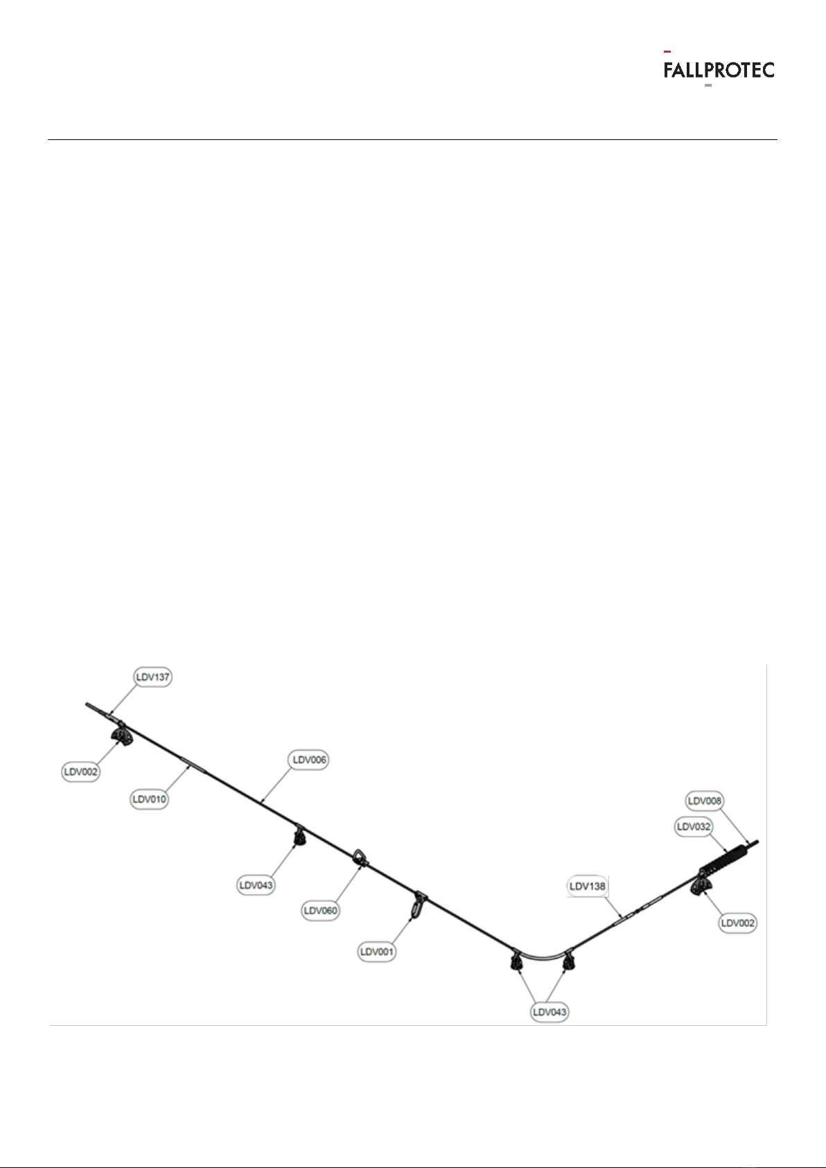
1.2. Overall scheme of the equipment ..............................................................................................................................................4
1.3. Description of the components................................................................................................................................................... 5
1.3.1. The wire rope............................................................................................................................................................................... 5
1.3.2. Terminale anchors...................................................................................................................................................................... 5
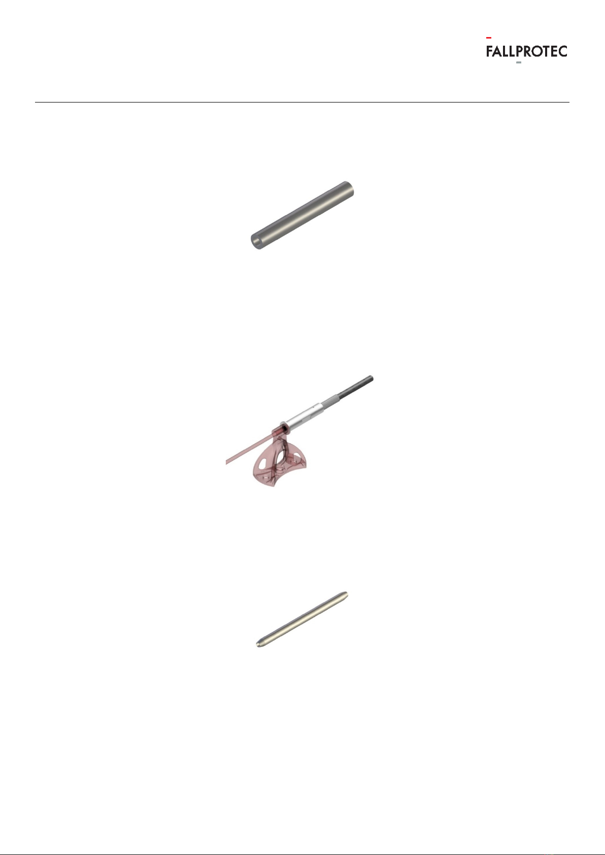
1.3.3. Intermediate anchor NEO........................................................................................................................................................ 5
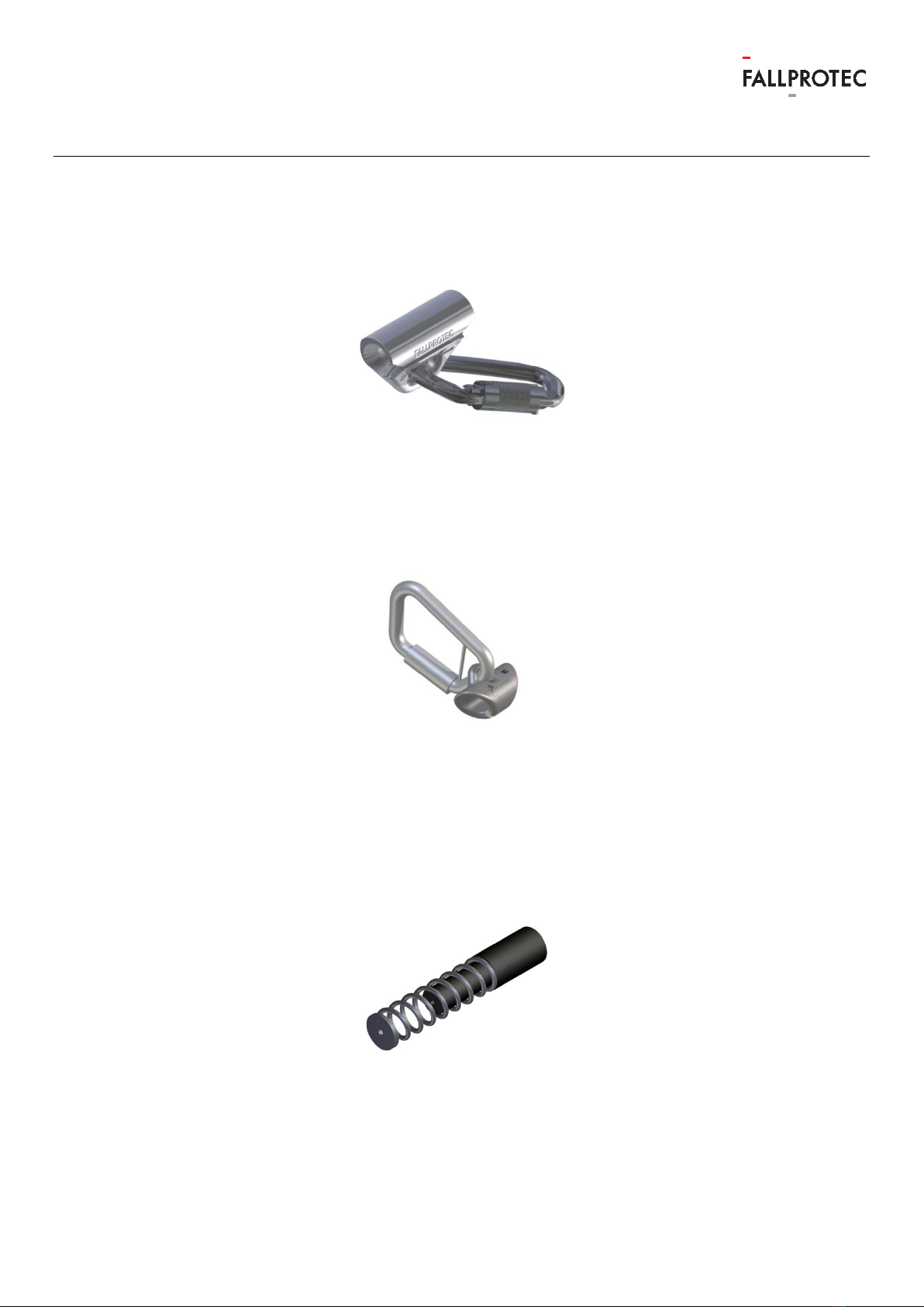
1.3.4. Glider............................................................................................................................................................................................... 6
1.3.5. Captive glider............................................................................................................................................................................... 6
1.3.6. Energy absorber ......................................................................................................................................................................... 6
1.3.7. Crimping ring 100mm ................................................................................................................................................................. 7
1.3.8. Line tensioner ............................................................................................................................................................................... 7
1.3.9. Crimping ring for junction ......................................................................................................................................................... 7
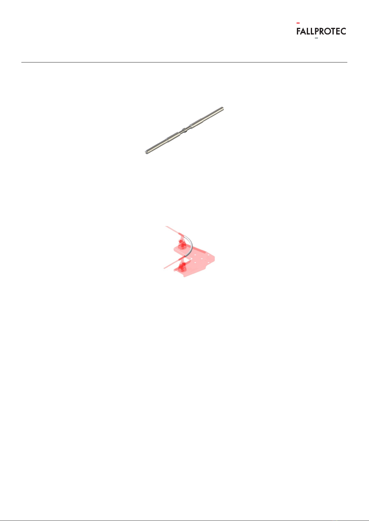
1.3.10. Turnbuckle .....................................................................................................................................................................................8
1.3.11. Cable guide for curve ................................................................................................................................................................8
2. Marking .............................................................................................................................................................................................................9
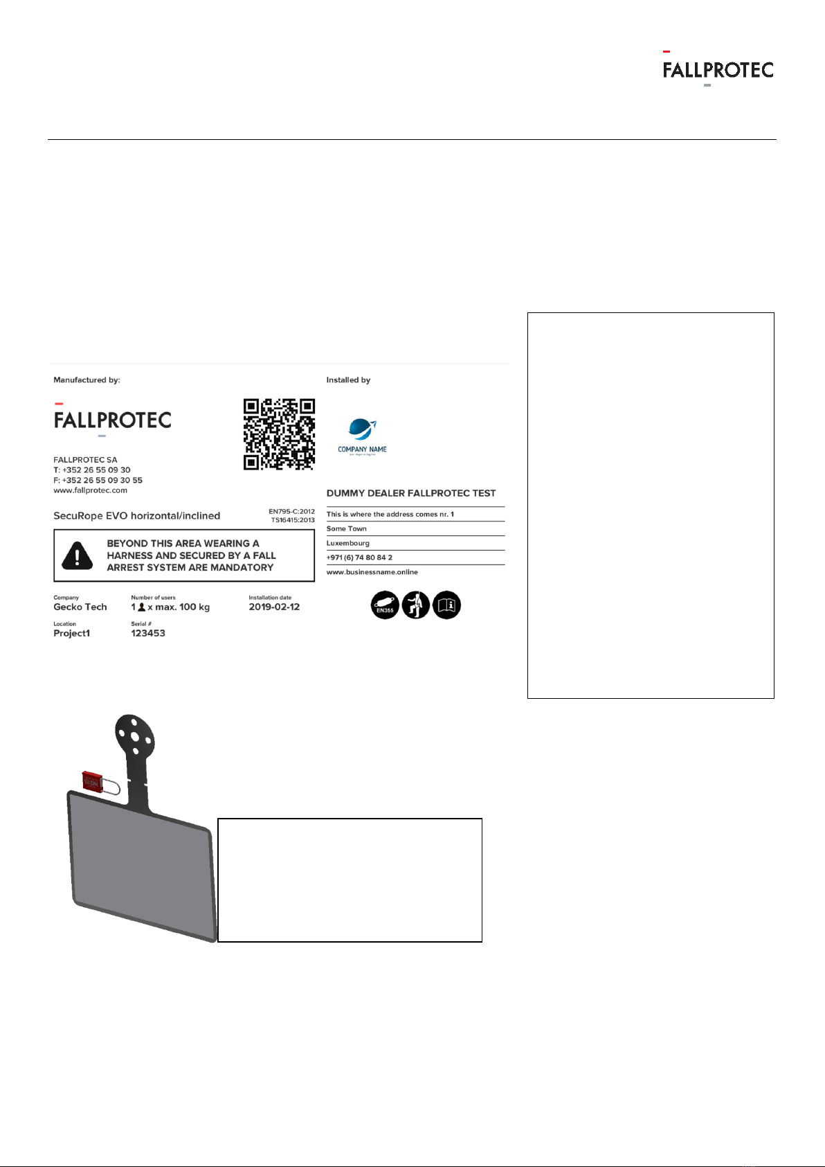
2.1. Warning plate..................................................................................................................................................................................... 9
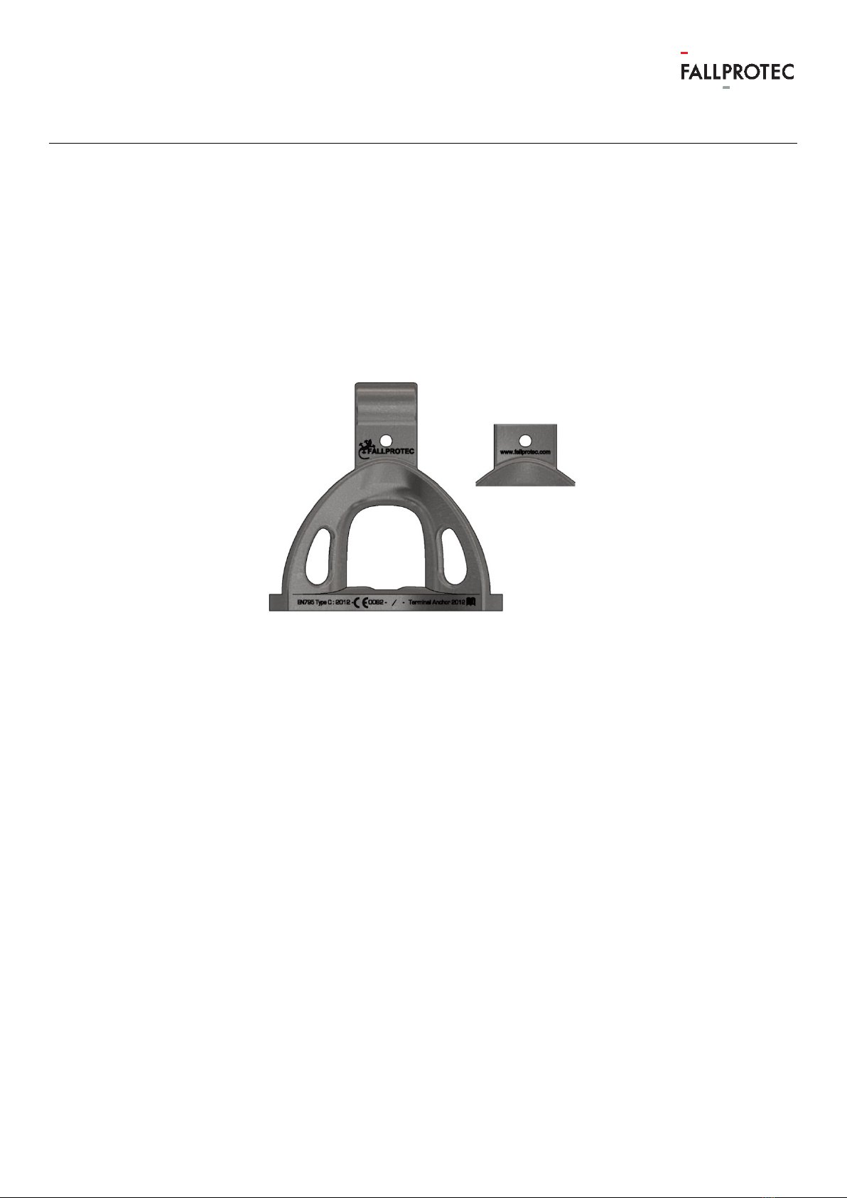
2.2. End anchor......................................................................................................................................................................................... 10
2.3. Intermediate anchor NEO ............................................................................................................................................................. 11
2.4. Glider..................................................................................................................................................................................................... 11
2.5. Captive glider.................................................................................................................................................................................... 12
2.6. Energy absorber .............................................................................................................................................................................. 12
3. Homologation............................................................................................................................................................................................... 13
4. Instruction for resale .................................................................................................................................................................................. 13
5. Skills of the installer ................................................................................................................................................................................... 13
6. Installation of Securope............................................................................................................................................................................ 13
6.1. Structure on which the Securope is installed ....................................................................................................................... 15
7. Personal protective equipment ............................................................................................................................................................. 16
8. Recommendations relating to the documentation required after installation...................................................................... 17
9. User manual .................................................................................................................................................................................................. 19
9.1. Preliminary check ............................................................................................................................................................................ 19
9.1.1. Attach to the cable ...................................................................................................................................................................20
9.1.2. Use of the glider LDV001.......................................................................................................................................................20
9.1.3. Circulating along the lifeline .................................................................................................................................................. 21
9.1.4. Use of a fall arrest block attached to the line ................................................................................................................. 21
9.1.5. Warning ......................................................................................................................................................................................... 21

User Manual
Securope 2012 horizontal
DOC039-UK-19.07.15
3
9.1.6. Prohibited use............................................................................................................................................................................ 22
9.1.7. Instructions for storage and maintenance....................................................................................................................... 22
9.1.8. Operational life of the installation....................................................................................................................................... 23
10. Recommandations relating of periodic review procedure......................................................................................................... 24

User Manual
Securope 2012 horizontal
DOC039-UK-19.07.15
4
1. Description
1.1. General
The SecuRope Lifeline System is permanently installed on a building or other structure which needs
to be maintained by personnel exposed to the risk of fall when carry out their maintenance work.
The SecuRope lifeline consists of a stainless steel wire rope fixed onto the supporting structure by
anchors placed regularly along the cable. One or more persons can attach themselves to the cable
by means of a mobile anchor point (further referred to the glider). The SecuRope lifeline enables the
user to move freely to any point on the lifeline where there is a risk of falling without the need to
detach themselves from the cable at any time.
The user wears a harness according to EN 361 fitted with a lanyard and a connector according to EN
362 and is attached to the life line using a glider.
1.2. Overall scheme of the equipment
LDV001 Glider
LDV002 Terminale Anchor
LDV006 The wire rope
LDV008 Crimping ring 100 mm
LDV010 Crimping ring for junction
LDV032 Energy absorber
LDV138 Turnbuckle
LDV043 Intermediate anchor
LDV060 Captive Glider
LDV137 Line tensioner

User Manual
Securope 2012 horizontal
DOC039-UK-19.07.15
5
1.3. Description of the components
1.3.1. The wire rope
The wire rope 8 mm diameter, construction 7x7 , material AISI 316
Fig. 1 LDV006 wire rope
1.3.2. Terminale anchors
Terminal anchors are installed at the ends of the line, material AISI 316
Fig. 2 LDV002 terminal anchor
1.3.3. Intermediate anchor NEO
Intermediate anchors are arranged along the lifeline at intervals between 2 and 12 m.
Material AISI 316
Fig. 3 LDV043 Intermediate anchor NEO

User Manual
Securope 2012 horizontal
DOC039-UK-19.07.15
6
1.3.4. Glider
The glider allows the user to attach himself on the line. The glider may be placed and removed from
the line. Material AISI 431.
Fig. 4 LDV001 Glider
1.3.5. Captive glider
The captive glider is permanently attached to the line. Material AISI 316.
Fig. 5 LDV060 Captive glider
1.3.6. Energy absorber
The energy absorber reduces the force which is transmitted to the building structure in case of a fall.
An energy absorber is mandatory when the line is less than 20 m.
Material polyurethane 95 shore.
Fig. 6 LDV032 Energy absorber

User Manual
Securope 2012 horizontal
DOC039-UK-19.07.15
7
1.3.7. Crimping ring 100mm
The crimping ring serves as a stop for the line.
Fig. 7 LDV008 Crimping ring 100mm
1.3.8. Line tensioner
The tensioner serves as a stop for the line and allows the tensioning of the line.
Fig. 8 The tensioner serves as a stop for the line and allows the tensioning of the line.
1.3.9. Crimping ring for junction
The crimping ring for junction allows end to end attachment of the wire rope.
Fig. 9 Crimping ring for junction

User Manual
Securope 2012 horizontal
DOC039-UK-19.07.15
8
1.3.10. Turnbuckle
The turnbuckle allows end to end attachment of the wire rope in case of a closed loop.
Fig. 10 LDV138 Turnbuckle
1.3.11. Cable guide for curve
The cable guide for curve is used in conjunction with the corner plate and allows the tensioning of
the cable from one of the ends of the line.
Fig. 11 LDV076 Cable guide for curve

User Manual
Securope 2012 horizontal
DOC039-UK-19.07.15
9
2. Marking
2.1. Warning plate
An identification plate is installed near to the zone where the users attach themselves to the line.
Our web portal Fallprotec Assistant generates the plate. It can be printed on a sticker provided by
Fallprotec (climate proof). The commissioning date must be on
the warning plate.
Manufacturer informations
and a QR code to get direct
access to all the informations
related to the installation
Equipment type and applied
standards.
Logo and installer name
Symbol indicating that it is
mandatory to use a fallarrest
harness according to EN355
Maximal number of users and
their weights
Information about the
installation place.
Commissioning date
It is mandatory to read the
user manual before use.
The serial number of the self-
locking tag
❾
The sticker will be fixed on a
bendable plate. A self-locking
Tag with a serial number has to
be fixed on the plate

User Manual
Securope 2012 horizontal
DOC039-UK-19.07.15
10
2.2. End anchor
Engraving shows :
-The name of the manufacturer : Fallprotec
-The name of the componant : Terminal Anchor
-The standard N° EN795 Type C : 2012
-The logo directing to read the user manual
-The batch number QQ/AA (quarter/year)
-Internet adress : www.fallprotec.com
Fig. 12 End anchor marking

User Manual
Securope 2012 horizontal
DOC039-UK-19.07.15
11
2.3. Intermediate anchor NEO
Engraving shows :
-The name of the manufacturer : Fallprotec
-The name of the componant : Terminal Anchor
-The standard N° EN795 Type C : 2012
-The logo directing to read the user manual
-The batch number QQ/AA (quarter/year)
-Internet adress : www.fallprotec.com
Fig. 13 LDV034 Intermediate anchor NEO marking
2.4. Glider
Engraving shows :
-The name of the manufacturer : Fallprotec
-The batch number (month/year)
-The standard N° EN795 Type C : 2012
-The CE mark
The logo directing to read the user manual
Fig. 14 Glider marking

User Manual
Securope 2012 horizontal
DOC039-UK-19.07.15
12
2.5. Captive glider
Engraving shows :
-The name of the manufacturer : Fallprotec
-The batch number (month/year)
-The standard N° EN795 Type C : 2012
-The CE mark
-The logo directing to read the user manual
Fig. 15 Captive glider marking
2.6. Energy absorber
Engraving shows :
-The name of the manufacturer : Fallprotec
-The batch number (month/year)
Fig. 16 Energy absorber marking

User Manual
Securope 2012 horizontal
DOC039-UK-19.07.15
13
3. Homologation
The Securope Life line Securope 2012 is an anchoring device in accordance with :
- Standard EN795:2012 - type C
- Standard CEN/TS16415 (4 users max) : Conformity certificate n°13.6.0803/A
The Securope 2012 life line has been subjected to a CE type examination by the notify body
APAVE SUDEUROPE SAS
8 rue Jean-Jacques Vernazza
Z.A.C. Saumaty-Séon - BP 193
13322 MARSEILLE CEDEX 16
CE certificate: n°0082/1084/160/04/14/0116 du 18/04/2014
Notify body bearing the number: 0082
Notify body in charge of checking the production: 0082
4. Instruction for resale
If the equipment is resold out of the first destination country, the reseller will provide instructions for
maintenance, for periodic reviews and instructions on repairs, in the language of the country of use.
5. Skills of the installer
The anchor device must be installed by competent persons or organizations that will have a
certificate of “approved installer” issued by Fallprotec.
The installation must be properly verified by calculation or testing.
The installation will be carried out in conformity with the Securope Installer manual DOC023-UK
6. Installation of Securope
The anchor device Securope is a horizontal lifeline system with a maximal inclination of 15°.
The user must be able to access and exit safely.
The installer must install the Securope lifeline so that the maximum angle at which the Securope
cable is allowed to penetrate or exit of the intermediate anchor does not exceed 15°.
The minimum clearance must be superior of the height of fall so that a falling user don’t hit an
obstacle during the fall.

User Manual
Securope 2012 horizontal
DOC039-UK-19.07.15
14
The height of fall is the sum of the terms given below :
-DDeflection: the deflection of the rigid anchor line
-HSafety : safety distance (1m)
-Fall clearanceRequired : minimal height calculated and required in case of a fall
-Fall clearanceAvailable : actual height available between the path and the first obstacle
-LPath : distance from the rigid anchor line to the edge
-LLanyard : lenght of the lanyard (< 2m)
-LAbsorber : deployment of the energy absorption system (< 0,8m)
-HUser: user’s height
Fall clearance
Available
Fall clearance
Required
= D
Deflection
+ L
Lanyard
+ L
Absorber
- L
Path
+ H
User
+ H
Safety
Fall clearance
Required
< Fall clearance
Available

User Manual
Securope 2012 horizontal
DOC039-UK-19.07.15
15
If the height of fall is to large, Fallprotec advise mounting 20 mm crimping rings on both sides of
each anchor means. The free length of cable can then be reduced to 5 times the distance between
two successive anchors, see Fallprotec calculation software.
The installer will write on the warning plate the maximum deflection of the wire rope in case of a fall.
Fallprotec provides a software Securope V5.0 for the calculation of the deflection.
6.1. Structure on which the Securope is
installed
A competent person will check the strength of the structure in relationship with forces transmitted by
the end and intermediate anchors when a fall is stopped. Fallprotec makes software available,
approved by the notify body, which works out the forces in accordance with the site configuration and
the number of users.
The components of the Securope line withstand without permanent deformation the forces indicated
to table below and present a safety coefficient of two. The forces calculated by the software must be
lower than the allowable forces. If you note a force beyond the allowable force it will be necessary to
change one or more parameters of calculation, either to decrease the number of users or to decrease
the distance between two anchors.
Component description Allowable force
kN
Breaking strength
kN
End anchor
18.5
50
Intermediate anchor
LDV004/043/083
9
24
Cable 7x7
18.5
37
Crimping
18.5
37
Glider
6
50
Fig. 17 Table showing the allowable forces

User Manual
Securope 2012 horizontal
DOC039-UK-19.07.15
16
7. Personal protective equipment
The Securope lifeline should be used in conjunction with height safety PPE in accordance with
EN354, EN355, EN361, EN362.
.
Fig. 18 HAR010 Longe simple avec absorbeur
Fig. 19 HAR018 / HAR013 Connecteur ½ tour
Fig. 20 HAR001 Harnais Prolight

User Manual
Securope 2012 horizontal
DOC039-UK-19.07.15
17
8. Recommendations relating to the
documentation required after installation
New requirements of EN795:2012
For the user, the documentation on the installation provides evidence that the installation was
performed correctly. In addition, it serves as an essential foundation for further examination of the
anchor, because, in many cases, fixing anchors are not visible or accessible.
After installation, the installer sends the user copies of the documentation for the installation. This
documentation must be kept in the building for subsequent reviews of the anchor.
Documentation on the installation must contain at least the following information:
- The address and location of the installation;
- The name and address of the company that carried out the installation;
- The name of the person responsible for the installation;
- The product identification (manufacturer of the anchor, type, model / item);
- The fixing device (manufacturer, product, and transverse tensile forces eligible);
- The schematic plan of the installation, for example the roof, and information relevant to the user,
such as the position of the anchor points (for example relevant in case of snow).
Should be marked on the schematic plan of the building so that it is visible or available to all (for
example, at the point of access to the roof).
The statements made by the responsible installer must be signed by him and attest that at
least the anchor:
- Has been installed in accordance with manufacturer's installation instructions;
- Is consistent with the plan;
- Was attached to the specified support;
- Has been set as specified (eg, number of bolts, correct materials, position / location correct);
- Was put into service according to information supplied by the manufacturer;
- Came with photographic information / documentation, especially when the fasteners (eg bolts)
and the underlying support are no longer visible once installation is complete.
When several anchor points must be photographed for identification purposes, it is recommended to
mark the anchoring devices with numbers and incorporate this numbering in the inspection records of
the anchoring device and the ground plan in the installation area.
Fallprotec provides the installer with a model for the "Installer schematic plan"

User Manual
Securope 2012 horizontal
DOC039-UK-19.07.15
18
Schematic plan of installation
Building / Structure
Adress :
Notes :
Order N°:
Type of order :
Shape of the roof :
Anchoring device: Class C- Lifeline
Client
Name :
Adress :
Contact :
Telephone N°:
Installer
Name :
Adress :
Installer chief:
Telephone N°:
Anchoring device
Manufacturer : FALLPROTEC
Model identification /type : Securope 2012
Building components
Attachments / Studs
Data of fixations
Ø drilled hole
Depth
Torque
mm
mm
N.m
Type :
Material :
Minimum distance from the edge (c):
Minimal axial distance (s):
Minimum thickness of the component:
Permissible tensile strength :
Breaking force :
Distance from the edge
Axial spacing
Cx:
Sx:
Cy:
Sy:
Notes:
Drilling method:
Test device:
Hammer
Rotative
Wrench
Cleaning of the drilled hole
Testing devise of fixations
System
impact
yes
Humid
yes
No
dry
No
Control list
Ground plan of the roof:
Substrate except exceptions
(no doubt on the capacity)
Installation in accordance
with manufacturer’s instructions
Recommended attachments
used
All attachements
photographed with
identification
Visibles attachments
Installation plan attached on
site
Screw immobilisation by
traversing fixing technique
Additional information
Breakout force (kN), required torque (Nm)
Anchoring point 1
Anchoring point 2
Anchoring point 3
Anchoring point 4
Anchoring point 5
Anchoring point 6
Anchoring point 7
Anchoring point 8
Anchoring point 9
Anchoring point 10
Anchoring point 11
Anchoring point 12
Anchoring point 13
Anchoring point 14
Anchoring point 15
Anchoring point 16
Adittional fixations:
Note of installation chief:
Date : Signature

User Manual
Securope 2012 horizontal
DOC039-UK-19.07.15
19
9. User manual
9.1. Preliminary check
The following checks are mandatory before using the SecuRope Lifeline.
oThe user of the lifeline must be in good physical condition, and not prone vertigo or giddiness.
oThe user must have received adequate training for the following
oUse of the fall protection equipment,
oWorking with the SecuRope lifeline,
oUse of the rescue equipment in the event of fall.
oA minimum of two people is required to work together on the lifeline, so that each can assist
the other in the event of an incident.
oA rescue plan must be in place to evacuate the person who fell within 15 minutes. The rescue
material must be easily accessible and be located in the vicinity from the lifeline.
oNo more than four people may be connected to the cable at the same time; however, the
manufacturer’s label clearly states the maximum number of people who may be connected to
the lifeline simultaneously, namely 1, 2, 3 or 4 persons.
oEach user must be equipped with :
oA suitable harness with two anchoring points, one at the back and one at the chest , in
conformity with the EN 361 standard,
oThe chest anchor point is the preferred point for anchoring the harness, the dorsal
anchoring point being used for rescue operations.
oAn energy absorber lanyard in conformity with EN 354/355 standard.
oTwo karabiners twist lock type in zinc plated steel, according to EN 362 and having the
following characteristics, length 105 mm, width 58 mm, wire diameter 10 mm, opening
20 mm, breaking strength 23 kn.
oOn arrival in the work area, or whenever the user attaches to the cable, he is required to
check :
oThat the manufacturer’s label is in place, and that it mentions the maximum number of
users who can connect to the lifeline simultaneously
oThat the fall indicator has not been activated.
oThat the glider, the harness and the lanyard are in good, working condition
oThat there is no obstruction under the walk way that could reduce the clearance
specified on the manufacturer’s label
oThe system must be immediately put out of service if the user notes one or more
anomalies to the points indicated above.
oChecking the Fall Indicator
oThe fall indicator is installed on the end anchor equipped with an energy absorber. The
user can normally reach the side of the final anchor.
oThe indicator is a spherical steel part, which rests on an elastic seat.
oIn the event of fall, the spherical part penetrates into the elastic seat.
oIf the user sees that the sphere is no longer visible, he must inform a qualified person
of the situation before using the line.

User Manual
Securope 2012 horizontal
DOC039-UK-19.07.15
20
Fig. 21 Fall indicator not activated Fig. 22 Fall indicator activated
9.1.1. Attach to the cable
The user attaches to the cable in an area where there is no risk of falling, in principle in the vicinity of
one of the two end anchors.
The user must use a mobile anchor point (hereinafter referred to glider) and the associated
connector.
9.1.2. Use of the glider LDV001
The glider is attached to the cable side to the user see Fig. 38
Fig. 23 Correct orientation of the glider
To connect the glider, the user tilts the glider, opens the locking device and fits the glider over the
cable - see Fig.7-8-9.
Fig. 24 Locking device open Fig. 25 Locking device closed Fig. 26 Karabiner on the glider
Table of contents
Other fallprotec Safety Equipment manuals
Popular Safety Equipment manuals by other brands

MSA
MSA AUER 3S-Basis Plus Operation manual

Grace Industries
Grace Industries SuperCELL SC500-H-IC User information

FTC
FTC CHOKER JOKER LIGHT Use and maintenance instructions

Thiele
Thiele TWN 0812 Mounting instructions

bolle SAFETY
bolle SAFETY TRYON RX quick start guide

RITE-HITE
RITE-HITE Dok-Lok STR-4000 installation manual