Il Dispositivo di Protezione Individuale di classe III 824.010 “BODY FUTURA” è:
- un bloccante ventrale, conforme alla norma EN 567:13 e allo standard UIAA 126, che
inserito su corde tessili conformi alle norme EN 564 (corde accessorie) o EN 892
(corde dinamiche) o EN 1891 (corde semi-statiche) di ø compreso tra 9 e 12 mm,
si blocca sotto carico in una direzione rimanendo libero di scorrere nella direzione
opposta (direzione d’uso);
- un risalitore della linea di lavoro, conforme alla norma EN 12841:06 tipo B, adatto alla
progressione verso l’alto su corde tessili di lavoro conformi alla norma EN 1891 (corde
semi-statiche) di ø compreso tra 10 e 12 mm, da utilizzare obbligatoriamente insieme
ad un dispositivo anticaduta, conforme alla norma EN 12841 tipo A o EN 353-2, inse-
rito sulla corda di sicurezza (come ad es. il BACK-UP).
Questi dispositivi funzionano perfettamente su corde tessili asciutte e pulite. Attenzio-
ne: Su corde sporche, unte, infangate, o ghiacciate, l’azione bloccante può ridursi gran-
demente no ad annullarsi e l’attrezzo può slittare lungo la corda. Questa situazione si
verica maggiormente su corde di piccolo diametro: per questo motivo si consiglia l’uso
di una corda di almeno 10 mm. Lo speciale dente forato, che facilita l’espulsione del fan-
go, attenua ma non annulla tale inconveniente. Attenzione: non usare assolutamente i
bloccanti su funi metalliche.
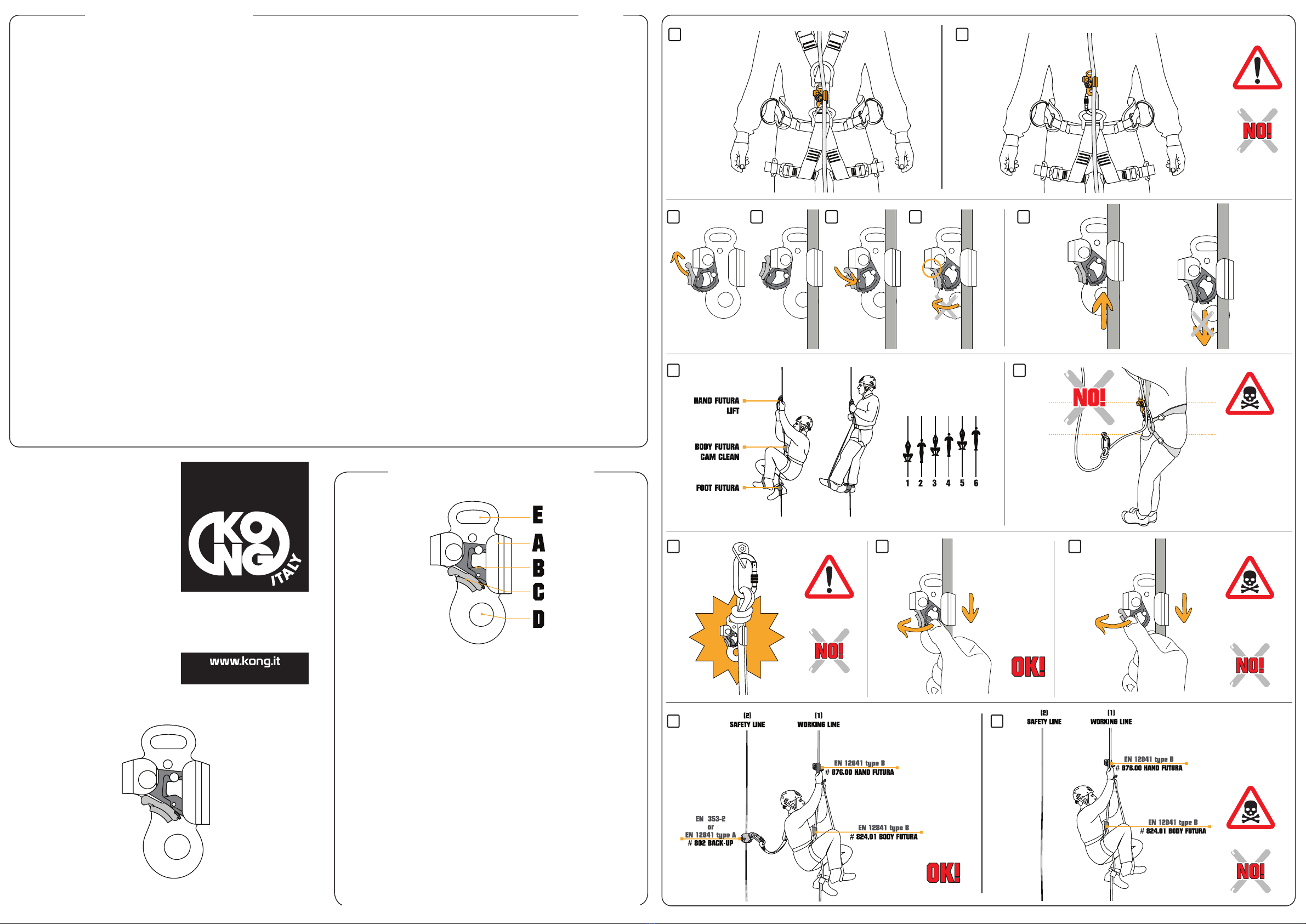
8.1 – COLLEGAMENTO ALL’IMBRACATURA
Fig. 1 - Collegare il BODY FUTURA:
- all’imbracatura bassa mediante una maglia rapida, inserita tra il foro (D) ed il punto di
attacco ventrale dell’imbracatura;
- alla parte alta dell’imbracatura/pettorale mediante un cordino o un connettore, inserito
tra l’asola (E) ed il punto di attacco della parte alta dell’imbracatura/pettorale, in modo
di mantenere il bloccante in posizione verticale e aderente al corpo per favorire lo
scorrimento sulla corda.
Attenzione: non utilizzare mai il bloccante ventrale senza collegarlo alla parte alta
dell’imbracatura/pettorale (g. 2).
8.2 – POSIZIONAMENTO SULLA CORDA
Fig. 3 - Corretto posizionamento del BODY FUTURA sulla corda:
- ruotare e bloccare in posizione aperta il dente portando il dispositivo di sicurezza all’e-
sterno del BODY FUTURA;
- inserire il BODY FUTURA sulla corda vericando la direzione di utilizzo marcata sull’at-
trezzo;
- sbloccare il dente, premendolo in direzione della corda;
- vericare che il dispositivo di sicurezza sia posizionato all’interno del BODY FUTURA
e che impedisca l’apertura completa del dente.
In condizioni di assoluta sicurezza, prima di utilizzare il BODY FUTURA, vericare che:
- si posizioni parallelamente alla corda;
- scorra nella direzione d’uso (verso l’alto);
- si blocchi nella direzione opposta (verso il basso) (g. 4).
8.3 – MODALITÀ DI UTILIZZO DEL BLOCCANTE VENTRALE (EN 567)
Fig. 5 – Il bloccante da piede “FOOT FUTURA”, utilizzato insieme ad una maniglia e/o
al BODY FUTURA, aiuta a mantenere verticale il corpo dell’utilizzatore facilitandone la
salita. Attenzione:
Attenzione:
- i bloccanti non sono dispositivi anticaduta: assicuratevi che non si creino laschi sulla
corda (g. 7);
- non spingere mai il bloccante contro il nodo: lo sbloccaggio può risultare molto difcol-
toso, se non impossibile (g. 7);
- il “FOOT FUTURA” non è un dispositivo di protezione individuale (DPI) e non deve
essere usato da solo;
- per far scorrere il bloccante verso il basso, azionare con il pollice la camma dentata
(g. 8), non azionare il dispositivo di sicurezza del dente (g. 9): rischio di apertura
accidentale.
8.4 – MODALITÀ DI UTILIZZO DEL RISALITORE DELLA LINEA DI LAVORO (EN
12841)
Fig. 3 – Corretto posizionamento sulla linea di lavoro (leggere p.to 8.2).
In condizioni di assoluta sicurezza, prima di utilizzare il BODY FUTURA, vericare:
- che si posizioni parallelamente alla corda;
- che scorra nella direzione d’uso (verso l’alto);
- che si blocchi nella direzione opposta (verso il basso) (g. 4);
- che non vi sia un lasco sulla corda di lavoro tra il punto di ancoraggio e l’utilizzatore;
- di essere collegati alla corda di sicurezza con un dispositivo anticaduta conforme alla
norma EN 12841 tipo A o EN 353-2 (come ad es. il BACK-UP).
Attenzione: prima di posizionare il BODY FUTURA sulla corda di lavoro vericare che:
- i punti di ancoraggio, sia della corda di lavoro e che della corda di sicurezza, siano
sopra l’utilizzatore e che siano conformi alla norma EN 795;
- i connettori siano dotati di dispositivo di bloccaggio della leva e conformi alla norma
EN 362, il sistema di collegamento della maniglia all’imbracatura non sia più lungo di
1 metro.
Fig. 10 – Esempio di corretto uso: l’utilizzatore effettua la progressione con una ma-
niglia e il BODY FUTURA sulla corda di lavoro (1) essendo contemporaneamente colle-
gato con un dispositivo anticaduta alla corda di sicurezza (2).
Fig. 11 – Esempio di non corretto e pericoloso uso: l’utilizzatore non è collegato alla
corda di sicurezza (2) con un dispositivo anticaduta.
9 – CONTROLLI PRE E POST USO
Controllate ed assicuratevi che il prodotto:
- non abbia subìto deformazioni meccaniche;
- non presenti segni di cricche o di usura, in particolare tenete sempre sotto controllo lo
stato di usura nella zona di scorrimento della corda e del foro previsto per il collega-
mento all’imbracatura bassa (D);
- inoltre, vericate che il dispositivo di sicurezza (C), quando rilasciato, si richiuda auto-
maticamente e completamente.
L’Équipement de Protection Individuelle de classe III 824.010 “BODY FUTURA” est :
- un bloqueur ventral, conforme à la norme EN 567:13 et au standard UIAA 126 lequel,
lorsque inséré sur cordes textiles conformes aux normes EN 564 (cordelettes) ou EN
892 (cordes dynamiques) ou EN 1891 (cordes tressées gainées à faible coefcient
d’allongement) de diamètres compris entre 9 et 12 mm, se bloque sous une charge dans
l’une des directions tout en restant libre de coulisser dans la direction opposée (direction
d’emploi);
- un dispositif d’ascension pour support de travail, conforme à la norme EN 12841:06 type
B, destiné à la progression vers le haut sur les cordes textiles conformes à la norme EN
1891 (cordes tresses gainées à faible coefcient d’allongement) de diamètres compris
entre 10 et 12 mm, à utiliser obligatoirement avec un dispositif antichute conforme à la
norme EN 12841 du type A ou EN 353-2, introduit sur la corde de sécurité (comme le
BACK-UP, par exemple).
Ces équipements fonctionnent parfaitement sur les cordes textiles sèches et propres. At-
tention : Sur des cordes sales, graisseuses, tachées de boue ou gelées, l’action bloquante
peut se réduire sensiblement jusqu’à s’annuler et l’outil peut déraper le long de la corde.
Cette condition se produit le plus souvent sur les cordes de diamètre réduit : pour cette
raison, l’utilisation d’une corde ’au moins 10 mm est conseillée. La fente d’évacuation
spéciale, qui facilite l’expulsion de la boue, atténue mais n’annule pas cet inconvénient.
Attention : surtout ne jamais employer les bloqueurs sur des cordes en métal.
8.1 – CONNEXION AU HARNAIS
Fig. 1 - Relier l’équipement :
- au bas du harnais à l’aide d’un maillon rapide introduit entre le trou inférieur (D) et le point
d’attache ventral du harnais;
- à la partie haute du harnais/torse à l’aide d’une cordelette ou d’un mousqueton, introduit
entre le trou supérieur (E) et le point d’attache de la partie haute u harnais/torse, de
façon à maintenir le bloqueur en position verticale et près du corps pour favoriser le
coulissement de la corde.
Attention: ne jamais utiliser le bloqueur ventral sans le relier à la partie haute du harnais/
torse (g. 2).
8.2 – POSITIONNEMENT SUR LA CORDE
Fig. 3 - Positionnement correct de l’équipement sur la corde :
- faire pivoter et bloquer la gâchette (B) en position uverte, en amenant le cran de sûreté
(C) à l’extérieur du corps (A);
- introduire l’équipement sur la corde en vériant la direction d’emploi marquée sur le corps
(A);
- débloquer la gâchette à picots (B) en la pressant en direction de la corde;
- vérier à ce que le cran de sûreté (C) soit positionné à l’intérieur du corps (A) et qu’il
empêche l’ouverture complète de la gâchette à picots (B).
Dans des conditions de sécurité absolue, avant d’utiliser l’équipement, vérier :
- qu’il se place parallèlement à la corde;
- qu’il coulisse dans la direction d’emploi (vers le haut);
- qu’il se bloque dans la direction opposée (vers le bas) (g. 4).
8.3 – MODE D’EMPLOI DU BLOQUEUR VENTRAL (EN 567)
Fig. 5 – Le bloqueur de pied “FOOT FUTURA”, utilisé avec une poignée et/ou avec BODY
FUTURA, aide à maintenir le corps de l’utilisateur en position verticale, tout en facilitant la
remontée.
Attention :
- ne jamais pousser l’équipement contre le noeud : le déblocage peut s’avérer particulière-
ment difcile, sinon impossible (g. 6);
- les bloqueurs/dispositifs d’ascension ne sont pas des dispositifs antichute : assurez-vous
que la corde soit toujours tendue (g. 7);
- “FOOT FUTURA” n’est pas un équipement de protection individuelle (ÉPI) et ne doit pas
être utilisé seul;
- pour faire coulisser l’équipement vers le bas, actionnez la gâchette à picots (B) avec votre
pouce, comme le montre la g. 8 ; ne pas actionner le cran de sûreté (g. 9) : risque
d’ouverture accidentelle.
8.4 – MODE D’EMPLOI DU DISPOSITIF D’ASCENSION OUR SUPPORT DE TRAVAIL
(EN 12841)
Fig. 3 - Positionnement correct pour support de travail (lire le point 8.2).
Dans des conditions de sécurité absolue, avant d’utiliser l’équipement, vérier :
- qu’il se place parallèlement à la corde;
- qu’il coulisse dans la direction d’emploi (vers le haut);
- qu’il se bloque dans la direction opposée (vers le bas) (g. 4);
- que la corde de travail n’ait pas de lâche entre le point d’ancrage et l’utilisateur;
- d’être relié à la corde de sécurité par un dispositif antichute conforme à la norme EN 12841
du type A ou EN 353-2 (comme le BACK-UP, par exemple).
Attention : avant de positionner le dispositif sur la corde de travail, vérier que :
- les points d’ancrage, tant des cordes de travail que de la corde de sécurité, soient au-
dessus de l’utilisateur et soient conformes à la norme EN 795;
- les connecteurs soient dotés d’un dispositif de blocage du doigt et conformes à la norme
EN 362;
- le système de connexion de la poignée au harnais ne soit pas d’une longueur supérieure
à 1 mètre.
Fig. 10 – Exemple d’emploi correct : l’utilisateur effectue la progression avec une poignée
et avec BODY FUTURA sur la corde de travail (1) tout en étant simultanément relié à la
corde de sécurité (2) avec un dispositif antichute.
Fig. 11 – Exemple d’emploi non correct et dangereux : l’utilisateur n’est pas relié à la
corde de sécurité (2) avec un dispositif antichute.
9 – CONTRÔLES AVANT ET APRÈS L’EMPLOI
Contrôlez et assurez-vous que le produit :
- n’ait subi aucune déformation mécanique,
- ne présente aucun signe de ssure ou d’usure ; surtout, maintenir toujours sous contrôle
l’état de l’usure de la zone de coulissement de la corde et du trou inférieur prévu pour la
connexion au bas du harnais (D).
- en outre, vérier que le cran de sûreté (C), lorsque déclenché, se referme automatique-
ment et complètement.
Die persönliche Schutzausrüstung der Klasse III 824.010 “BODY FUTURA” ist:
- eine Gurtklemme, die nach EN 567:13 und UIAA 126 zertiziert ist und die auf Textilseilen
gemäß den Normen EN 564:06 (Hilfsseile) oder EN 892:04 (dynamische Seile) oder EN
1891:98 (halbstatische Seile) mit einem ø zwischen 9 und 12 mm eingesetzt wird und die
unter Belastung in einer Richtung klemmt und dabei weiter ungehindert in die entgegen
gesetzte Richtung (Einsatzrichtung) gleitet.
- eine Seilklemme des Steigseils, nach EN 12841:06 Typ B, geeignet für dem Aufstieg auf
Textilseilen nach EN 1891 (halbstatische Seile) mit einem ø zwischen 10 und 12 mm, die
obligatorisch mit einer Absturzsicherung nach EN 12841 Typ A oder EN 353-2 benutzt
warden muss, die auf dem Sicherheitsseil angeschlossen sein uss (beispielsweise BACK-
UP).
Diese Vorrichtungen funktionieren perfekt auf trockenen und sauberen Textilseilen. Achtung:
Auf verschmutzten, fettigen, verdreckten oder vereisten Seilen kann sich die Klemmwirkung
stark verringern und sogar ganz aufgehoben werden und die Ausrüstung kann auf dem Seil
abrutschen. Diese Situation tritt vorwiegend bei Seilen mit geringem Durchmesser ein: Aus
diesem Grund wird empfohlen, ein Seil mit einem Durchmesser von mindestens 10 mm zu
verwenden. Der spezielle durchbohrte Zahn, der den Schmutzaustritt erleichtert, mildert
diesen Nachteil, hebt ihn aber nicht ganz auf. Achtung: Die Steigklemmen niemals auf
Metallseilen verwenden.
8.1 – ANSCHLUSS AN DEN KLETTERGURT
Abb. 1 – Ausrüstung anbringen:
- mit einem Schließring mit Schnellöffnung am Hüftgurt, der zwischen dem Loch (D) und der
Bauchöse des Klettergurts eingesetzt wird;
- am oberen Teil des Klettergurts/Brustgurts mit einem Seil oder Karabiner, der zwischen der
Öse (E) und der oberen Anschlagpunkt des Klettergurts/Brustgurts eingesetzt ist, um die
Klemme in vertikaler Position und in Körpernähe zu halten und das Gleiten auf dem Seil zu
begünstigen.
Achtung: Niemals die Gurtklemme benutzen, ohne diese mit dem oberen Teil des Gurts oder
den Brustgurt am oberen Loch zu verbinden (Abb. 2).
8.2 – POSITIONIERUNG AUF DEM SEIL
Abb. 3 – Korrekte Positionierung der Ausrüstung auf dem Seil:
- Den Klemmzahn (B) drehen und in geöffneter Position klemmen und dazu die
Sicherheitsvorrichtung (C) außen auf dem Körper (A) ziehen;
- Die Ausrüstung auf dem Seil einsetzen und die auf dem Körper (A) markierte
Anwendungsrichtung prüfen;
- Den Klemmzahn (B) freigeben und diesen dabei in Seillaufrichtung drücken;
- Kontrollieren, dass die Sicherheitsvorrichtung (C) innerhalb des Körpers (A) positioniert ist
und dass sie die komplette Zahnöffnung (B) verhindert.
Vor dem Gebrauch der Ausrüstung und unter absoluten Sicherheitsbedingungen prüfen, dass:
- diese sich parallel zum Seil positioniert;
- in die Anwendungsrichtung gleitet (nach oben);
- in der entgegen gesetzten Richtung klemmt (nach unten) (Abb. 4).
8.3 – ANWENDUNG DER GURTKLEMME (EN 567)
Abb. 5 – Die Fußklemme “FOOT FUTURA”, die usammen mit einem Griff und/oder BODY
FUTURA verwendet wird, hilft den Körper des Anwenders vertical zu halten, was den Aufstieg
erleichtert.
Achtung:
- die Seil- /Steigklemmen sind keine Fallsicherungen: Sicherstellen, dass es keine losen
Stellen auf dem Seil bilden (Abb. 6);
- Die Klemme nie gegen den Knoten schieben: Das Lösen kann erschwert oder gar unmöglich
sein (Abb. 7);
- “FOOT FUTURA” ist keine persönliche Schutzausrüstung (PSA) und darf deshalb nicht
alleine verwendet warden;
- Um die Ausrüstung nach unten zu verschieben, die Zahnklemme (B) mit dem Daumen
betätigen (Abb. 8), nicht die Sicherheitsvorrichtung des Zahns betätigen (Abb. 9): Gefahr
einer ungewollten Öffnung.
8.4 – ANWENDUNG DER STEIGKLEMME AUF DEM STEIGSEIL (EN 12841)
Abb. 3 – Richtige Positionierung auf dem Steigseil (siehe Punkt 8.2).
Vor dem Gebrauch der Ausrüstung und unter absoluten Sicherheitsbedingungen prüfen, dass:
- diese sich parallel zum Seil positioniert;
- in die Anwendungsrichtung gleitet (nach oben);
- in der entgegengesetzten Richtung klemmt (nach unten) (abb. 4);
- dass kein Spiel auf dem Steigseil zwischen der Anschlagstelle und dem Anwender vorhanden
ist;
- dass Sie an einem Sicherheitsseil mit Fallsicherungsvorrichtung nach EN 12841 Typ A oder
EN 353-2 angeschlossen sind (z.B. BACK-UP).
Achtung: Vor dem Positionieren der Ausrüstung auf dem Seil muss kontrolliert werden, dass:
- Die Anschlagstellen sowohl des Steigseils als auch des Sicherheitsseils sich oberhalb des
Anwenders benden und der EN 795 entsprechen,
- die Karabiner mit Klemmvorrichtungen des Hebels versehen sind und der EN 362
entsprechen,
- das Verbindungssystem des Griffs mit dem Gurt nicht länger als 1 Meter ist,
Abb. 10 – Beispiel für korrekte Anwendung: Der Anwender steigt mit einem Griff und BODY
FUTURA auf dem Steigseil (1) nach oben und ist gleichzeitig mit einer Fallsicherung am
Sicherheitsseil (2) befestigt.
Abb. 11 – Beispiele für falschen und gefährlichen Gebrauch: Der Anwender ist nicht mit
einer Fallsicherung am Sicherheitsseil (2) befestigt.
9 – KONTROLLEN VOR UND NACH DEM GEBRAUCH
Kontrollieren Sie das Produkt und stellen Sie sicher, dass das Produkt:
- keine mechanischen Verformungen erlitten hat;
- keine Anzeichen von Rissen oder Verschleiß aufweist;
- Kontrollieren Sie insbesondere die Abnutzung in den Gleitzonen des Seils und des Lochs für
den Anschluss an den Hüftgurt (D), Außerdem sicherstellen;
- dass die Sicherheitsvorrichtung (C), wenn sie losgelassen wird, sich automatisch und
vollkommen schließt.
El EPI de la clase III 824.010 “BODY FUTURA” es:
- un bloqueador ventral, en cumplimiento de la norma EN 567:13 y del estándar UIAA 126
que, situado en cuerdas textiles conformes a las normas EN 564 (cuerdas auxiliares) o
EN 892 (cuerdas dinámicas) o EN 1891 (cuerdas trenzadas con funda, semiestáticas)
con ø comprendido entre 9 y 12 mm, se bloquea bajo carga en una dirección aunque se
desliza libremente en la dirección opuesta (dirección de uso);
- un ascendedor de la línea de trabajo, en cumplimiento de la norma EN 12841:06 tipo
B, idóneo para la progresión hacia arriba en cuerdas textiles conformes a la norma EN
1891 (cuerdas trenzadas con funda, semiestáticas) con ø diámetro comprendido entre
10 y 12 mm, que usar obligatoriamente con un equipo anticaídas conforme a la norma
EN 12841 tipo A o EN 353-2, situado en la cuerda de seguridad (por ejemplo el BACK-
UP).
Estos equipos funcionan perfectamente en cuerdas textiles secas y limpias. Atención: En
cuerdas sucias, grasientas, con barro o heladas, la acción bloqueante puede reducirse
enormemente hasta anularse y el equipo puede deslizarse por la cuerda. Esta situación
se produce sobre todo en cuerdas con un diámetro pequeño: por eso se aconseja usar
cuerdas con un diámetro mínimo de 10 mm. El especial diente perforado, que facilita la ex-
pulsión del barro, reduce pero no anula este problema. Atención: no use absolutamente
los bloqueadores en cuerdas metálicas.
8.1 - CONEXIÓN AL ARNÉS
Fig. 1 - Conecte el dispositivo:
- al arnés inferior mediante un eslabón rápido, situado entre el agujero (D) y el punto de
enganche ventral del arnés;
- a la parte superior del arnés/pectoral mediante un cordel o un conector, situado entre el
ojal (E) y el punto de enganche de la parte superior del arnés/pectoral para mantener
el bloqueador en una posición vertical y adherente al cuerpo con el n de facilitar el
deslizamiento en la cuerda.
Atención: no use nunca el bloqueador ventral sin conectarlo a la parte superior del arnés/
pectoral (g. 2).
8.2 – POSICIONAMIENTO EN LA CUERDA
Fig. 3- Posicionamiento correcto del dispositivo en la cuerda:
- gire y bloquee en posición abierta la leva dentada (B) situando el dispositivo de seguridad
(C) en el exterior del cuerpo (A);
- coloque el dispositivo en la cuerda, verique la dirección de uso marcada en el cuerpo
(A);
- suelte la leva dentada (B), presione el dispositivo de seguridad (C) en dirección de la
cuerda;
- para comprobar que dicho dispositivo se encuentre dentro del cuerpo (A) y que impida la
apertura completa de la leva dentada (B).
En condiciones de seguridad absoluta, antes de usar el dispositivo, compruebe que:
- se coloque paralelamente a la cuerda;
- se deslice en la dirección de uso (hacia arriba);
- se bloquee en la dirección opuesta (hacia abajo) (g. 4).
8.3 - MODO DE USO DEL BLOQUEADOR VENTRAL (EN 567)
Fig. 6 – El bloqueador de pie “FOOT FUTURA”, usado con un puño y/o el BODY FUTURA,
ayuda a mantener vertical el cuerpo del usuario al facilitar la subida.
Atención:
- los bloqueadores/ascendedores no son equipos anticaídas: asegúrese de la ausencia de
holguras en la cuerda (g. 6);
- el “FOOT FUTURA” no es un equipo de protección individual (EPI) y por tanto no debe
usarse solo;
- no empuje nunca el dispositivo contra el nodo: el desbloqueo puede resultar muy dicul-
toso e incluso imposible (g. 7);
- para deslizar el dispositivo hacia abajo, accione con el pulgar la leva dentada (B) como
en la g. 8, no accione el dispositivo de seguridad del diente (g. 9): riesgo de apertura
accidental.
8.4 - MODO DE USO DEL ASCENDEDOR DE LA LÍNEA DE TRABAJO (EN 12841)
Fig. 3 - Posicionamiento correcto en la línea de trabajo (lea el punto 8.2).
En condiciones de seguridad absoluta, antes de usar el dispositivo, compruebe:
- que se coloque paralelamente a la cuerda;
- que se deslice en la dirección de uso (hacia arriba);
- que se bloquee en la dirección opuesta (hacia abajo) (g. 4);
- que no haya un juego en la cuerda de trabajo entre el punto de anclaje y el usuario;
- que esté conectado a la cuerda de seguridad por medio de un equipo anticaídas confor-
me a la norma EN 12841 tipo A o EN 353-2 (por ejemplo, el BACK-UP).
Atención: antes de posicionar el dispositivo en la cuerda de trabajo compruebe que:
- los puntos de anclaje en la cuerda de trabajo y en la cuerda de seguridad se encuentren
por encima del usuario y cumplan la norma EN 795;
- los conectores cuenten con el dispositivo de bloqueo del gozne y cumplan la norma EN
362;
- el sistema de conexión del puño al arnés no mida más de 1 metro de largo.
Fig. 10 – Ejemplo de uso correcto: el usuario realiza la progresión con un puño y el
BODY FUTURA en la cuerda de trabajo (1) estando conectado a la vez con un equipo
anticaída a la cuerda de seguridad (2).
Fig. 11 – Ejemplo de uso no correcto y peligroso: el usuario no está conectado a la
cuerda de seguridad (2) con un equipo anticaída.
9 – CONTROLES ANTES Y DESPUÉS DEL USO
Controle y compruebe que el producto:
- no haya sufrido deformaciones mecánicas,
- no presente indicios de rajas o desgaste, en particular controle siempre el estado de
desgaste en la zona de deslizamiento de la cuerda y del agujero previsto para la cone-
xión al arnés inferior (D);
- asimismo, verique que el dispositivo de seguridad (C), al soltarlo, se cierre automática
y completamente.
8 – INFORMAZIONI SPECIFICHE
Teste de référence: ITALIENNE Referenztext: ITALIENISCH Texto maestro: ITALIANO
8 – INFORMATIONS SPÉCIFIQUES 8 – SPEZIFISCHE ANGABEN 8 - INFORMACIÓN ESPECÍFICA
Type of rope
Tipo di corda
Type de corde
Seiltyp
Tipo de cuerda
EN 1891/A
EN 564 - EN 892
EN 1891/A
ø ...÷... mm
Rope diameter (min-max)
Diametro corda (min-max)
Diamètre de la corde (min.-max.)
Seildurchmesser (min-max)
Diámetros cuerda (min-max)
Direction of use
Direzione d’uso
Mode d’emploi
Anwendungsrichtung
Dirección de uso
Device for one person only
Dispositivo per una sola persona
Équipement pour une seule personne
Ausrüstung für eine einzelne Person
Equipo para una sola persona
MADE BY:
MARKING • MARCATURA
MARKIERUNG • MARQUAGE • MARCADO
KONG s.p.a. Via XXV Aprile, 4 - (zona industriale)
I - 23804 MONTE MARENZO (LC) - ITALY
www.kong.it/conformity
NB n° 0123 TÜV SÜD
Product Service GmbH
Daimlerstraße 11
85748 Garching - Germany
Download the declarance of conformity at:
Scarica la dichiarazione di conformità a :
Télécharger la déclaration de conformité à:
Laden Sie die Konformitätserlärung herunter zu:
Descargue la declaración de conformidad en:
CERTIFIED BY • CERTIFICATO DA
CERTIFIÉ PAR • ZERTIFIZIERT VON • CERTIFICADO POR