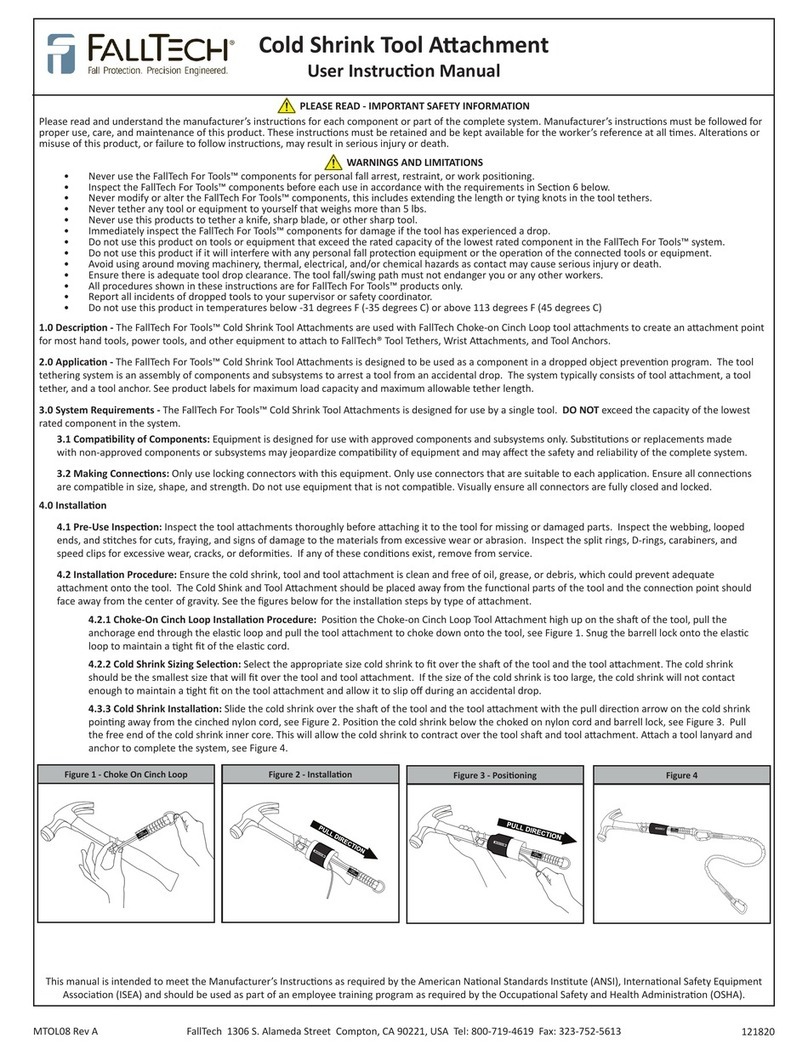
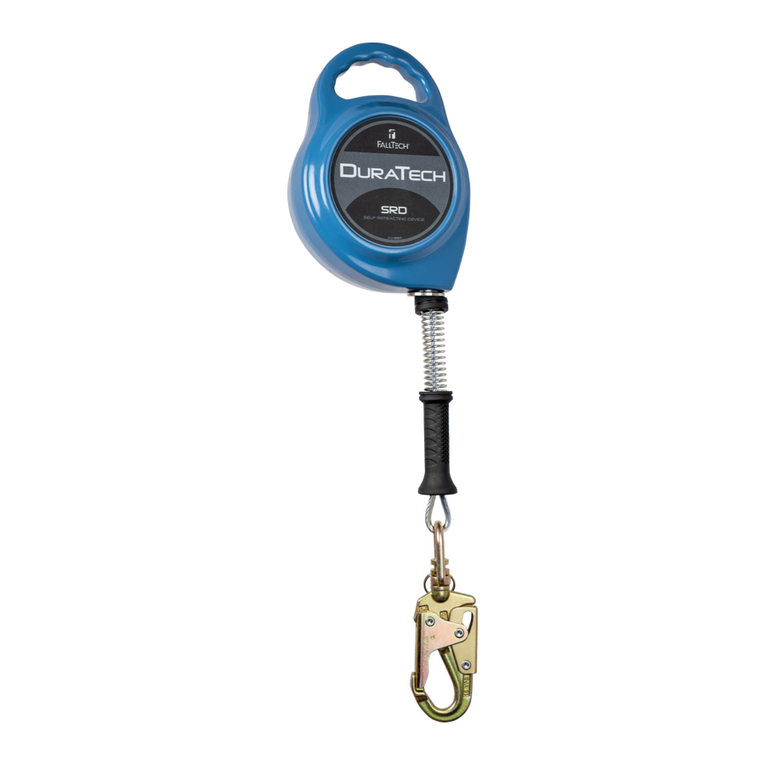
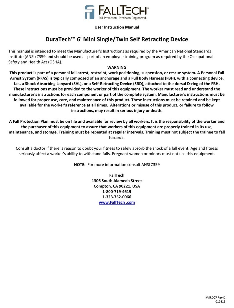
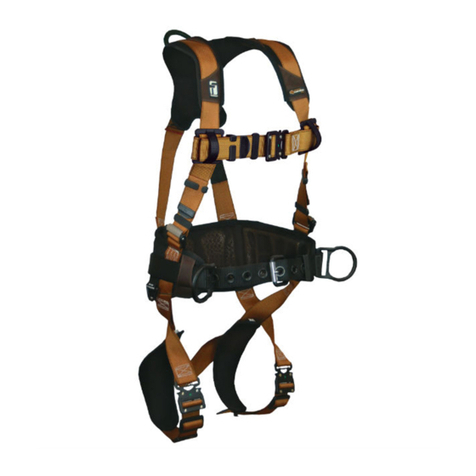
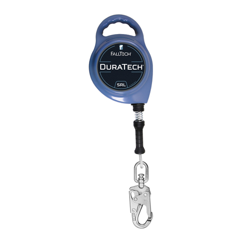
Falltech D-Ring Extender Operator's manual

D-Ring Extender
User Instrucon Manual
MDRE01 Rev B 112618

Table of Contents
6
10
10
12
2MDRE01 Rev B 112618

1.0 Warnings and Important Informaon
•
•
•
•
•
•
•
•
•
•
•
•
•
WARNING
IMPORTANT
MDRE01 Rev B 112618

2.0 Descripon
• Type A:
• Type B:
• Type C:
• Type D:
Type Product Image
A
B
C
D
Figure 1 - About FallTech® D-Ring Extenders
3.0 Applicaon
3.1 Purpose:
A
B
C
or
D
BA
either CDB
Figure 2A: Typical PFAS Applicaon with D-Ring Extender
MDRE01 Rev B 112618

MDRE01 Rev B 112618
A
B
C
D
E
F
Figure 2B: Fall Arrest and Restraint with D-Ring Extenders
WARNING
Do not aach an Energy Absorbing Lanyard (EAL) or other connector to the dorsal D-Ring of a Full Body Harness (FBH) when using a D-Ring ex-
tender. Two acve connectors on a single D-ring is not in compliance with ANSI requirements or OSHA regulaons.
DO NOT
3.1.1 Fall Restraint:
3.1.2 D-Ring Extender for Fall Arrest Applicaon:
3.2 Applicaon Limits:
DO NOT:
•
•
•
•
3.2.1 Posioning, Suspension, Rescue:

6MDRE01 Rev B 112618
A
B
C
D
E
F
G
Figure 3 - Incorrect Connecons
4.0 System Requirements
4.1 Capacity:
NOTE:
4.2 Compability of Connectors:
4.3 Compability of Components:
4.4 Making Connecons:
4.5 Personal Fall Arrest System:
4.5.1 PFAS Anchorage Strength:
•
•
4.6 Restraint System:

5.0 Installaon and Use
MDRE01 Rev B 112618
NOTE:
DO NOT
5.1 Anchorage Locaon:
DO NOT
5.2 Fall Clearance Distance:
Figure 4: Minimum Required Fall Clearance:
D-Ring Extender and 6 Energy Absorbing Lanyard
A
Length of Shock Absorbing Lanyard
B
Elongaon/Deceleraon Distance
C Length of D-Ring Extender (18”)
D
Harness Stretch and Dorsal D-Ring Shi
E
Height of Dorsal D-ring
F
Safety Factor
G Total Minimum Clear Fall Distance Required
NOTE: Use of an extender will increase the users potenal fall distance. The user must be sure the increased total length of a lanyard is
accounted for in calculang fall clearance distances, including swing fall. Be aware that when using an SRL, there may be addional fall clearance
required depending on anchor point locaon. If unsure, consult a Competent Person.
B
D
E
Figure 5 - Swing Fall Hazards: Overhead
5.3 Swing Fall:

8MDRE01 Rev B 112618
5.4 General Installaon Requirements:
NOTE:
5.5 Use the Type A, B, and C D-Ring Extenders as Extensions:
Type A and Type D:
A
B
C
or
D
BA
either CDB
Figure 6: Suitable Use of D-Ring Extender Type A and Type D
Type B:
A
B
C
Figure 7: Aaching Choke Loop Extender Type B to Dorsal D-Ring

A
B
C
or
D
BA
either CDB
Figure 8: Suitable Use of D-Ring Extender Type B
Type C:
A
B
C
or
D
BA
either CDB
Figure 9: Suitable Use of D-Ring Extender Type C
MDRE01 Rev B 112618
DO NOT
•
•
5.6 Aer a Fall:

6.0 Maintenance, Service and Storage
Keep the unit clean and free of a build-up of contaminants and corrosion.
6.1 Storage:
6.2 Remove From Service:
7.0 Inspecon
10MDRE01 Rev B 112618

11MDRE01 Rev B 112618

8.0 Labels
12MDRE01 Rev B 112618

9.0 Denions
Anchorage -
Anchorage Connector -
Arrest Distance -
Authorized Person –
Available Clearance -
Capacity -
Cercaon -
Cered Anchorage -
Clearance -
Clearance Requirement -
Competent Person -
Component -
Connecng Subsystem -
Connector -
Deceleraon Distance -
Energy (Shock) Absorber -
Fall Arrest -
Fall Hazard -
Free Fall -
Free Fall Distance -
Harness, Full Body -
Horizontal Lifeline –
Horizontal Lifeline Subsystem –
MDRE01 Rev B 112618

Horizontal Lifeline –
Horizontal Lifeline Subsystem –
Lanyard -
Lanyard Connecng Subsystem -
Personal Fall Arrest System (PFAS) -
Posioning -
Posioning Lanyard -
Qualied Person -
Rescuer -
Self-Retracng Lifeline (SRL) -
Snaphook -
Swing Fall -
MDRE01 Rev B 112618

APPENDIX A
MDRE01 Rev B 112618
Table 1A: Specicaons for DuraTech Leading Edge SRL-LE
Designaon Type
and Item #
Descripon and
Dimensions
Minimum Material
Tensile Strength Capacity and Standards Image
Type A
8202
Type B
Type C
Type D
Note:
Table of contents
Other Falltech Protection Device manuals