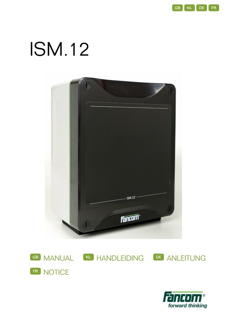
Fancom WEBLINKBOX User manual

WEBLINKBOX
G
INSTALLATION MANUAL
N
INSTALLATIEHANDLEIDING
D
INSTALLATIONSANLEITUNG
F
NOTICE D’INSTALLATION
VERSION A2
GNDF

N.B.: The original, authentic version of this manual is the English version produced by
Fancom B.V. or one of its daughter companies (referred to further as Fancom). Any
modifications introduced to this manual by third parties have neither been checked nor
approved by Fancom. Modifications are taken by Fancom to include translations into
languages other than English and the insertion and/or deletion of text and/or
illustrations to/from the original contents. Fancom cannot be held liable for any
damages, injury, guarantee claims and other claims relating to this type of
modification, in as far as these modifications result in a content that differs from the
original English version of this manual produced by Fancom. For the latest information
about product installation and operation, please contact the customer service dept.
and/or the technical service dept. of the Fancom company concerned. In spite of the
care taken when compiling this manual, if you should discover any errors, please
inform Fancom B.V. in writing. Fancom B.V., PO Box 7131, 5980 AC Panningen (the
Netherlands).
Copyright © 2014 Fancom B.V.
Panningen (the Netherlands)
All rights reserved. Nothing from this manual may be copied, distributed or translated
into other languages, partly or wholly, without express prior written permission from
Fancom. Fancom reserves the right to modify this manual without notice. Fancom can
give no guarantee, neither implicit nor explicit, for thismanual. All risks arefor the user.
This manual has been compiled with the utmost care. If, however, you should discover
an error, please inform Fancom B.V.
Art.Nr. 5911788
GB140401
Gndf

Gndf
i
g
Table of contents
1. General introduction.........................................................................................1
1.1 Documentation with the control computer................................................1
1.2 How to use this manual............................................................................1
1.3 Fancom helpdesk.....................................................................................2
1.4 F-Central FarmManager™ .......................................................................2
2. Safety instructions and warnings....................................................................2
3. WebLinkBox......................................................................................................4
4. Basic functions .................................................................................................4
4.1 Login ........................................................................................................4
4.2 Changing your password..........................................................................5
4.3 Logout......................................................................................................5
5. Connecting the WebLinkBox...........................................................................6
5.1 Connecting the WebLinkBox directly to the PC........................................6
5.2 Including the WebLinkBox into an existing local network.........................8
5.3 Setting the local network to be able to connect via the Internet..............10
6. Adding and configuring controllers..............................................................11
7. Frequently Asked Questions .........................................................................13
7.1 How can I switch between user and installer screens?..........................13
7.2 How can I check the speed of the network card?...................................13
7.3 Is it possible to login with more than one person?..................................14
7.4 My IP-address is lost, how can I return to the factory default settings?..14
7.5 How can I check if the connetion settings are correct? ..........................14
8. Appendix 1: Overview WebLinkBox board...................................................16
9. Appendix 2: Side view WebLinkBox board...................................................17
10. Appendix: EG-declaration of compliance.....................................................18

Gndf
1
g
1. General introduction
This manual has been compiled with the utmost care. If, however, you should discover
an error, please inform Fancom B.V.
1.1 Documentation with the control computer
The documentation consists of the following manuals:
•User's manual
The user's manual is intended for the end user. This manual supplies information
about working with the WebLinkBox after installation.
•Installer's manual
The installer's manual is intended for installers. This manual supplies information
about connecting and configuring the WebLinkBox.
Always keep this manual close to the WebLinkBox.
1.2 How to use this manual
The following symbols are used in this manual:
Tips and suggestions.
Note providing recommendations and additional information.
Warning indicating damage to the product if you do not follow
procedures carefully.
Warning indicating danger to humans or animals.
Electrical shock hazard. Danger to humans and animals.
Example of a practical application of the described functionality.
Calculation example.
Describes the key combinations for arriving at a particular screen.
Decimals
The control computer and this manual use a decimal point in values. For example: a
weight is shown as 1.5 kg (not as 1,5 kg).

Gndf
2
g
1.3 Fancom helpdesk
For any questions and support, please contact the local Fancom Sales & Service
Center.
1.4 F-Central FarmManager™
Virtually all Fancom equipment can be controlled and managed from a centrallocation.
This requires the F-Central FarmManager software package and a communication
module. The screens in the control computers are also used in F-Central
FarmManager. This means you can start working immediately.
2. Safety instructions and warnings
Read the safety instructions, regulations and conditions carefully before installing
and/or using the system. Installing the device and remedying any malfunctions must
only be carried out by an authorized installer, according to the prevailing regulations.
The guarantee will not apply if this product is built into a switch box in any way other
than that indicated by Fancom.
The network module is a piece of electronic apparatus. There is alwaysa risk of
a malfunction occurring. Fancom hasmade every effort to ensure that analarm
is given in the event of an emergency. Unfortunately, a 100% guaranteed
cannot be provided as not all circumstances are under Fancom's control.
Fancom cannot be held liable for any damage caused by incorrect settings
and/or non or partial functioning of the entire installation. Ask your installer if
the alarm outputsof each control computer have been
connected to a separate
alarm circuit.
Inspect the network module regularly for any damage. Report any damage to
your installer immediately. A damaged control computer is dangerous!
Do not use running water (high pressure cleaners) to clean your control
computer. The network module is water resistant, but not waterproof! Do not
switch off the network module when houses are unoccupied; otherwise there is
the risk of condensation forming in the network module.

Gndf
3
g
When mounting the computer, the following should be observed:
Never mount the network module near water pipes, drainage pipes etc.
Never mount the network module in a place where the weather has direct
influence (not in the sun, or in places where the temperature can rise sharply,
etc.).
Never mount the network module in a humid and/or dusty room and certainly
not in the room where the animals are present.
No condensation may take place in or on the network module.
Use the holes behind the cover screws on the corners of the box to securely
fasten the network module.
Use gland nutsto connect the network module. Use the sealing plates supplied
to seal the gland nuts which are not used. Seal all gland nuts after connection
to prevent the entry of dust, aggressive gases and/or humidity.
To protect against lightning, place an over voltage protection device in the
power supply of the network module.
Take precautions against electrostatic discharge (ESD) when working on the
control computer. Ensure the workplace is clean and dry.
Use the wiring/cables indicated on the connection diagrams and follow all
instructions (see installer manual). Only apply power after the wiring has been
connected correctly. Incorrect connections can cause permanent damage.
Before a new fuse i
s placed, the cause of the defect should be remedied by an
authorized installer. Only replace a defective fuse by a fuse of the same type
(see connection diagram).

Gndf
4
g
3. WebLinkBox
The WebLinkBox is an interface between the controller and a PC. Controller data are
exchanged with the PC. The WebLinkBox can be accessed through the FarmManager
software as well as a web browser. This manual will help to work with the device
correctly. Chapter 4 explains some basic functions. The next chapters explain how to
connect the WebLinkBox correctly. To be able to work with the WebLinkBox proceed
as follows:
1. Connect the WebLinkBox directly to the PC (see page 6)
2. Include the WebLinkBox into an existing local network (see page 8)
3. Set the local network to be able to connect via the internet (see page 10)
If you have connected the WebLinkBox you can add and configure the controllers (see
page 11).
4. Basic functions
4.1 Login
To login to the WebLinkBox via a web browser perform the following steps:
1. Start a web browser on the PC.
2. Enter the IP-address of the WebLinkBox in the address bar and click Enter:
3. Login with your password. The main menu appears:
•Click a control computer name to go to the control panel of that control
computer.
•Click System Configuration to configure control computers (see page 11).

Gndf
5
g
•Click Change password to change your password (see page 5).
•Click Log out to logout (see page 5).
If a password isentered incorrectlythree timestheWebLinkBoxwill be blocked
temporarily (5 minutes). The following message will appear on the screen:
System temporarily blocked.
The standard user’s password is 0000. The standard installer's password is
1234.
If someone has already logged in the following message will appear on the
screen: Another session is currently active. It is not possible to login with
more than one person.
Please contact Fancom if you have lost your password.
4.2 Changing your password
There are two valid passwords: one for the user and one for the installer. After logging
in click Change password to enter a new password. Enter the new password twice and
click Send to confirm the password.
Both passwords must be unique and the password has a maximum of 5
characters.
To block the change password function, set dipswitch 3 to On.
4.3 Logout
When you are logged in go to the main menu and click the Logout button.
It is important to always log out!
If you forget to log out, log in will only be possible again after 5 minutes. If the
user does not request a new screen for 5 minutes, the WebLinkBox will
automatically log out. The user must now log in again.
Place dipswitch 4 to On to set automatic log out and block log in to 1 minute
instead of 5 minutes.

Gndf
6
g
5. Connecting the WebLinkBox
5.1 Connecting the WebLinkBox directly to the PC
Connect the WebLinkBox to the network card of the PC using the yellownetwork cable
(cross cable). The figure below shows the connection scheme.
Disconnect the power before installation.
Figure 1: Connection scheme to connect the WebLinkBox directly to the PC.
Creating connection settings to connect the WebLinkBox to the PC
To be able to work with the WebLinkBox you have to create a network between the
WebLinkBox and the PC. To set up a network you have to perform the following steps:
The network
card must be suitable for connection to a 10Mbit device. For more
information see page 13.
1. Start the PC and go to Start Control panel.
2. Double click Network connections.
3. Right click the LAN connection you want to use.

Gndf
7
g
4. Select Properties.
5. Select Internet Protocol TCP/IP.
6. Click Properties.
Write down the original settings. If the pc has to return to a local network
reinstate the original settings.

Gndf
8
g
7. Change the settings of the Internet Protocol to:
IP address 192.168.2.111 (the last number may be chosen between 0 - 254, as
long as the address is unique in the local network)
Subnet mask 255.255.255.0
The netmask indicates which IP-addresses can be identified by the network
card. In the example of 255.255.255.0 the network card can only communicate
with network devices with an IP-address beginning with 192.168.2.x.
8. Press 2x OK.
If you don’t want to connect theWebLinkBox to a network you are finished after
completing this step.
5.2 Including the WebLinkBox into an existing local network
Connect the WebLinkBox to a local network card of the PC using the blue network
cable (patch cable). The figure below shows the connection scheme.
Disconnect the power before installation.
Figure 2: Connection scheme to connect the WebLinkBox to the PC with a switch /
router.
If you already have an existing network you can make the WebLinkBox part of this
network. Therefore you have to determine if it is necessary to change the network
settings. If the network has the same IP-address range as shown in the table below
you do not have to change settings. The WebLinkBox can then be connected to a free
port in the network using a normal network cable (not the supplied yellow cross cable).
If the network has a different IP-address range as shown in the table, the standard
IP-address of the WebLinkBox must be changed (see paragaph 5.2.2).

Gndf
9
g
IP-Address range Subnet mask
192.168.xx 255.255.0.0
192.168.2.x 255.255.255.0
Changing the standard IP-address
After changing the IP-address you can check if the settings are correct. See
page 14.
Change the standard IP-address on the PC
To change the standard IP-address of the WebLinkBox you have to perform the steps
explained in paragraph "Creating connection settings to connect the WebLinkBox to
the PC" page 6.
Reserve an IP-address that is not yet in use in the current network. This
IP-address will be assigned to the WebLinkBox as described in the next
section.
Change the standard IP-address on the WebLinkBox
To change the standard IP-address on the WebLinkBox:
1. Start a web browser on the PC.
2. Enter the IP-address of the WebLinkBox in the address bar and login using the
installer’s password.
3. Go to the window System configuration:

Gndf
10
g
4. Change the settings of the Internet Protocol to:
IP address The unique reserved IP-address in the previous step.
Subnet mask Same as entered on the PC.
5. Click on Send configuration.
The setting will only apply after the WebLinkBox has been off and on once.
If you want to use loop communication then you have to activate it (default loop
communication is off). In the drop down menu Select second port select
Current-Loop. The WebLinkBox will automatically search for the right baudrate.
At the bottom op the page the Current-Loop status will be displayed.
Reinstate the IP-address of the PC
1. Reinstate the IP-address of the PC (see paragraph "Creating connection settings to
connect the WebLinkBox to the PC" page 6).
2. Remove the yellow cross cable.
3. Reconnect the PC to the network by using the original network cable.
4. Connect the WebLinkBox with the normal network cable to a free port in the
network.
If you do not want to set the local network for global access you are finished
after this step.
5.3 Setting the local network to be able to connect via the Internet
Connecting with a VPN connection
For connection via the Internet Fancom advises a VPN connection. VPN can be used
to set up a connection between a device (e.g. pda, smartphone and PC) and your local
network with theWebLinkBox. Once this connection is made the device behaves like it
is connected directly to the local network and can connect to the WebLinkBox. Setting
up a VPN network can be done with a commercial available VPN solution. Contact
your local IT provider to install a VPN solution according to your needs.

Gndf
11
g
Connecting using portforwarding
The WebLinkBox behaves like a web server. When you have a permanent high speed
Internet connection this server can be made accessible via the IP-address you
received from you local Internet Service Provider. The used technique is called
portforwarding. The settings for portforwarding must be made in the router and/or DSL
modem which are used in your local network. Check the manual of your router how to
set up portforwarding or contact your local IT provider.
Application Port Protocol
Web pages 80 TCP/IP
FarmManager 10000 UDP
Ports and protocols available for portforwarding in the WebLinkBox.
This setup is much less secure than using a VPN solution. Always change the default
passwords to avoid unwanted access.
The portfor webpagescan be changed in theWebLinkBox. Login as installerand go to
the System configuration page. Add /showport to the URL in the address bar of your
browser and press Enter. An extra edit value for the port setting will occur. If the port
number is not default the edit value will always be visible at the System configuration
page. Port numbers are valid between 1024 and 65535.
6. Adding and configuring controllers
In the installer environment you can add and configure connected controllers in the
WebLinkBox. To add and configure the WebLinkBox perform the following steps:
1. Login using the installer password and click Send.
2. Click Control configuration.

Gndf
12
g
3. Choose one of the following options:
a. Click New scan for controls if you want to activate the WebLinkBox to search for
connected controllers (this may take some time).
b. Click Rescan for controls if you want to activate the WebLinkBox to search for
missing controllers.
c. Click Erase all if you want to erase all retrieved text files of the controllers.
The following window appears if you have chosen option a or b.
If several controllers are connected they will be categorized according to type
(F2000, 700, FC) and then according to the computer number as set in the
controllers.
4. Enter the controller name.
Naming a controller will make it visible on the main page. If the controller is
added without a name,
the name of the controller will be used. Only F2000 controls have a name, 700/
FC systems always have to be given a name.
5. Select the checkbox behind the controller name to add the controller to the list of
controllers on the main page.
6. Click Apply.
Only 1 controller or section can be added or removed at the same time. There
is a maximum of 50 sections/controls. Deactivated sections/controls also
count.
To remove a controller
from the list of controllers on the main page deactivate
the checkbox behind the controller name and click apply.
On the main page the name of the controller will appear followed by the type of
controller and program version. Click on the name of the controller to access the
settings of the controller. concerned.

Gndf
13
g
7. Frequently Asked Questions
7.1 How can I switch between user and installer screens?
When you are logged in as installer it is possible to switch between user screens and
installer screens on a F2000 controller. Double click on the back button ( ) to go from
installer screens to the user screens. Double click on the upper left soft button ( ) to
go from user screens to the installer screens.
7.2 How can I check the speed of the network card?
If the WebLinkBox is connected directly to the PC ensure the network card is suitable
for a 10Mbit device. Do this by setting the speed of the network card to Auto:
1. Start the PC and go to Start Control panel.
2. Double click Network Connections.
3. Right click the network adapter used for the WebLinkBox and choose Properties.
4. Click Configure and choose tab page Advanced.
5. Select Speed & Duplex at the left side. Now the Value option appears on the right
side.
6. Select Auto.
7. Click OK to finish.

Gndf
14
g
7.3 Is it possible to login with more than one person?
No, only one person may be logged in at the same time.
Go to the main page and logout to be able to login using a different web browser or PC.
After 5 minutes of non-activity the WebLinkBox automatically logs off. You will have to
login again to continue. Set dipswitch 4 to On, to set this automatic logout time to 1
minute.
7.4 My IP-address is lost, how can I return to the factory default
settings?
If the IP-address of the WebLinkBox is lost it is always possible to return to the factory
default settings. Using a paperclip press for about 5 seconds on the button Next to the
Ethernet connection (see chapter 8). The green LED next to the power supply will
illuminate. The WebLinkBox has now reverted to the IP-address 192.168.2.100 and
netmask 255.255.0.0.
7.5 How can I check if the connetion settings are correct?
Check LAN connection
To check the new LAN settings you have to double click the LAN connection icon (see
paragraph "Creatingconnection settingsto connect theWebLinkBoxto the PC" page 6
step 1 until 4) and select tab page Support. The new LAN settings are shown in the
window as follows:

Gndf
15
g
Check the WebLinkBox connection with a web browser
If the network settings are correct you can access the WebLinkBox via a web browser.
Start a web browser on the PC and enter the IP-address of the WebLinkBox in the
address bar. As soon as a web page appears with an login code this means the
network has been configured correctly and the WebLinkBox can be used.
The web browser must support Java scripts. Web browsers on PC’s and
notebooks usually support this. However this is not always the case with pda’s
en smartphones.The defaultbrowser delivered with an Iphone, Ipad or android
device supports this feature. Olderdevices with Pocket Internet Explorer do not
support Java scripts. Test your device for proper use.

Gndf
16
g
8. Appendix 1: Overview WebLinkBox board
Component Description Colour
CN 1 Boot connector
CN 2 FNet and Current loop connector
CN 3 Ethernet connection
CN 4 Power 5 Volt +/- 3%
CN 5 Connection for Wireless Module
LED 1 FNet Transmit Red
LED 2 IO-net or Current loop Red
LED 3 Ethernet active Yellow
LED 4 Ethernet link Green
LED 5 Supply voltage present Red
LED 6 Run led Green
LED 7 UDP communication Yellow

Gndf
17
g
9. Appendix 2: Side view WebLinkBox board
Component Description
5Vdc Power connector
Ehternet Network cable connector
Reset Reset to default IP-settings (press 5 sec.)
Dipswitch S 1 IO-net termination resistor
Dipswitch S 2 FNet termination resistor
Dipswitch S 3 Block password change
Dipswitch S 4 Auto logout after 1 or 5 minutes
R- Loop connection
R+ Loop connection
T+ Loop connection
T- Loop connection
Gnd Loop connection
Fnet Fnet connection
The dipswitch functions are not active in the Off position.
Table of contents
Languages:
Other Fancom Computer Hardware manuals
Popular Computer Hardware manuals by other brands

Panasonic
Panasonic 2SB1679G Specification sheet

Sony
Sony BKDS-7200K1 installation manual

Cypress Semiconductor
Cypress Semiconductor CY7C1471V33 Specification sheet

Global Fire Equipment
Global Fire Equipment J-NET-SP installation manual

Pico Macom
Pico Macom DSP806 Specifications

Thermalright
Thermalright Silver Arrow T8 installation manual