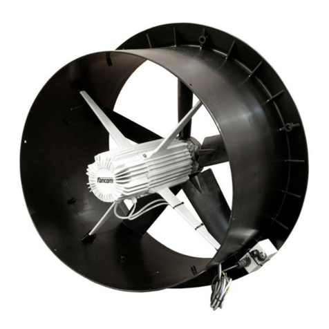
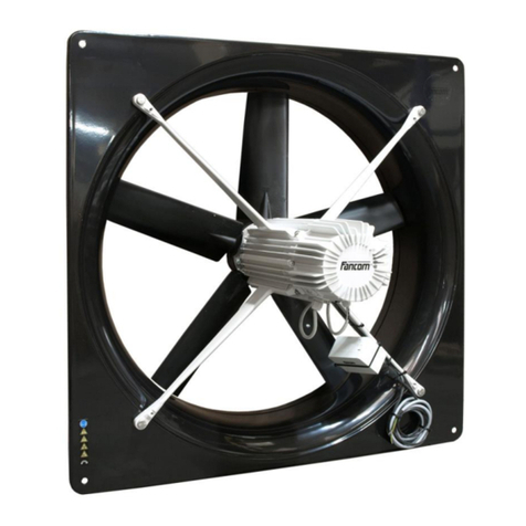
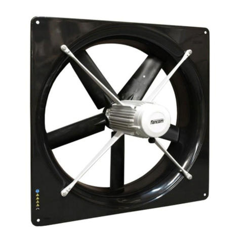
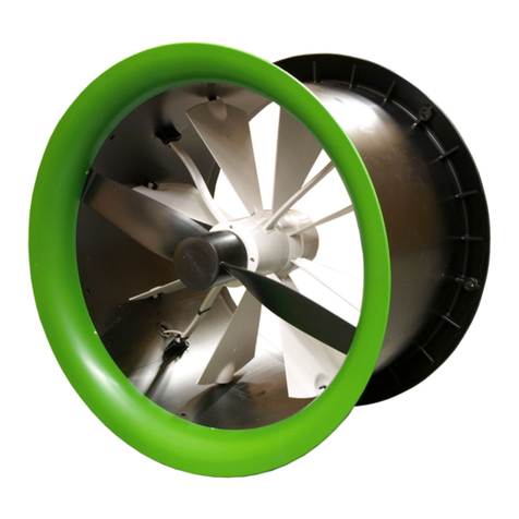
Fancom I-FAN COMPLETE User manual

I-FAN COMPLETE
G
MANUAL NHANDLEIDING DANLEITUNG
F
NOTICE IMANUALE
GNDFI

Gndfi
g
N.B.: The original, authentic version of this manual is the English version produced by Fancom B.V. or one of its
daughter companies (referred to further as Fancom). Any modifications introduced to this manual by third parties
have neitherbeen checkednor approved by Fancom. Modifications are taken byFancomto include translations into
languages other than English and the insertion and/or deletion of text and/or illustrations to/from the original
contents. Fancom cannot be held liable for any damages, injury, guarantee claims and other claims relating to this
type of modification, in as far as these modifications result in a content that differs from the original English version
of this manual produced by Fancom. For the latest information about product installation and operation, please
contact the customerservice dept. and/or the technical service dept. of the Fancomcompany concerned. In spite of
the care taken when compilingthis manual, if you should discover any errors, please inform Fancom B.V. in writing.
Fancom B.V., PO Box 7131, 5980 AC Panningen (the Netherlands).
Copyright © 2013 Fancom B.V.
Panningen (the Netherlands)
All rights reserved. Nothing from this manual may be copied, distributed or translated into other languages, partly or
wholly, without express prior written permission from Fancom. Fancom reserves the right to modify this manual
without notice. Fancom can give no guarantee, neither implicit nor explicit, for this manual. All risks are for the user.
This manual has been compiled with the utmost care. If, however, you should discover an error, please inform
Fancom B.V.
Art.Nr. 5911801
GB130715

Gndfi
i
g
Table of contents
1. General introduction .................................................................................................................................. 1
1.1 How to use this manual..................................................................................................................1
1.2 Fancom helpdesk........................................................................................................................... 1
1.3 Safety instructions and warnings....................................................................................................1
2. Installing the I-fan....................................................................................................................................... 2
2.1 Mount the I-fan and manual control................................................................................................2
2.2 Connect the I-fan and manual control (MCA) .................................................................................5
2.3 Install the protective screen (optional)............................................................................................ 9
2.4 Test the I-fan ................................................................................................................................ 11
3. Using the I-fan........................................................................................................................................... 11
3.1 First use........................................................................................................................................ 11
3.2 Control options ............................................................................................................................. 11
3.3 Malfunctions ................................................................................................................................. 12
3.4 Maintenance................................................................................................................................. 12
4. Technical specifications .......................................................................................................................... 13
5. EG declaration of conformity................................................................................................................... 14

Gndfi
1
g
1. General introduction
This manual has been compiled with the greatest possible care. Should you nonetheless discover an error, we
kindly request that you inform Fancom B.V..
1.1 How to use this manual
The following symbols are used in this manual:
Tips and suggestions.
Note providing recommendations and additional information.
Warning indicating damage to the product if you do not follow procedures carefully.
Warning indicating danger to humans or animals.
Electrical shock hazard. Danger to humans and animals.
Example of a practical application of the described functionality.
Calculation example.
1.2 Fancom helpdesk
For any questions and support, please contact the local Fancom Sales & Service Center.
1.3 Safety instructions and warnings
Before installing and commissioning the I-fan, read the safety instructions, provisions and conditions carefully. This
paragraph contains a number of general safety instructions. In the following paragraph, a number of specific safety
instructions are included in the installation instruction. The installation of the device and remedying of any
malfunctions should be performed by a certified electrical installer according to the applicable norms. The guarantee
does not applyif this product is installed in anyother way than is indicated by Fancom and if the product's motor has
been opened and changes have been made to the product.
Never install a damaged I-fan! Notify your supplier of any damages.
Parts of this product may have sharp edges. Wearing safety gloves is therefore recommended.
Prevent electrostatic discharge (ESD) when working on the I-
fan. Ensure that the workplace is clean and
dry.

Gndfi
2
g
2. Installing the I-fan
Install the I-fan and associated components as follows:
1. Mount the I-fan and manual control (MCA) (see page 2)
2. Connect the I-fan and manual control (MCA) (see page 5)
3. Install the protective screen (optional) (see page 9)
4. Test the I-fan (see page 11)
2.1 Mount the I-fan and manual control
Mount the I-fan
Mount the I-fan in or on a solid structure.
The direction of airflow must be from the motor to the impeller.
There must be sufficient free airflow available to cool the motor.
Take care to use suitable mounting material. The I-fan can be mounted on the wall with 4 screws.
Most I-fan units are too heavy to lift. Take the necessary precautions.
Fancom recommends mounting the I-fan as follows:
5. Disassemble the I-fan from the shroud.

Gndfi
3
g
6. Make a hole in the wall. Take the dimensions of various types of I-fan into account here.
Type A
mm
(inch)
B
mm
(inch)
Ø C
mm
(inch)
Ø D
mm
(inch)
Ø E
mm
(inch)
ØF
mm
(inch)
G
mm
(inch)
H
mm
(inch)
I
mm
(inch)
Ø J
mm
(inch)
K
mm
(inch)
..35
445
(17.5)
405
(15.9)
8
(0.3)
346
(13.6)
365
(14.4)
380
(15)
95
(3.7)
255
(10)
15
(0.6)
127
(5)
430
(16.9)
..40
495
(19.5)
455
(17.9)
8
(0.3)
396
(15.6)
415
(16.3)
440
(17.3)
110
(4.3)
240
(9.4)
15
(0.6)
127
(5)
500
(19.7)
..45
575
(22.6)
535
(21.1)
8
(0.3)
446
(17.6)
465
(18.3)
500
(19.7)
110
(4.3)
240
(9.4)
15
(0.6)
127
(5)
560
(22)
..50
635
(25)
595
(23.4)
8
(0.3)
496
(19.5)
515
(20.3)
560
(22)
110
(4.3)
240
(9.4)
15
(0.6)
127
(5)
630
(24.8)
..56
725
(28.5)
685
(27)
8
(0.3)
556
(21.9)
575
(22.6)
615
(24.2)
110
(4.3)
240
(9.4)
15
(0.6)
127
(5)
690
(27.2)
..63
805
(31.7)
750
(29.5)
11
(0.4)
629
(24.8)
644
(25.4)
698
(27.5)
130
(5.1)
240
(9.4)
20
(0.8)
150
(5.9)
758
(29.8)
..80
970
(38.2)
910
(35.8)
14.5
(0.6)
789
(31.1)
806
(31.7)
872
(34.3)
190
(7.5)
326
(12.8)
20
(0.8)
186
(7.3)
960.5
(37.8)
..92
1070
(42.1)
1010
(39.8)
14.5
(0.6)
902
(35.5)
914
(36)
980
(38.6)
188
(7.4)
326
(12.8)
22
(0.9)
186
(7.3)
1143
(45)
7. Secure the shroud of the I-fan to the wall.

Gndfi
4
g
8. Attach the I-fan inside the I-fan shroud.
Check whether the I-fan can spin freely and that the screw fittings are on the underside of the motor.
9. Place the protective screen on the I-fan (optional).
Placement of a protective screen is necessary if the I-fan:
•is within reach of animals and/or people, and
•is installed at heights less than 2.7 m above the floor.
The blades of the I-fan may run backward due to external influences. To prevent the I-fan turning in the
opposite direction, it is necessary to place a shutter. If the rotating speed of the blades in the opposite
direction is higher than 25% of the I-fan unit's maximum RPM, the I-fan is no longer able to reverse the
blades to the correct direction of rotation. Then, the I-fan will not start and will sound an alarm.
Mount the manual control (optional)
Below is an example of where the connection box(es) and the manual controls may be placed.
The manual control can be connected to 1 or more fans (a maximum of 3).
Option 1: Connecting the local manual control
1. Mount the local manual control.
2. Replace the connection box delivered by default.

Gndfi
5
g
Option 2: Connecting the central manual control
1. Mount to the central manual control.
2. Install a cable between the central manual control and the connection box(es) on the fan(s).
2.2 Connect the I-fan and manual control (MCA)
Before connecting, turn off the power and turn it back on only after the entire installation is ready.
The motor/thermal protection is already integrated in the I-fan.
Do not connect more than two I-fan units to one fuse.
Make sure that the I-fan is well and properly grounded according to the guidelines.
Keep signal and power cables as short as possible.
Place cables preferably in a duct (separate signal cables from power supply cables).
Connect the I-fan and manual control as follows:
1. Connect the control (see page 5)
2. Check the jumper settings on the MCA (see page 6)
3. Set the I/O address (see page 7)
4. Connect the power supply (see page 9 )
Connect the control
Without manual control
Digital control via I/O network and alarm (MCA) Analogue control and alarm (MCA)
Alarm contact, unpowered: 2A/30Vac/60Vdc

Gndfi
6
g
With manual control
In order to connect the regulator's analogue output, the standard connection Analogue In (3) and Gnd (4)
must first be removed from the cover.
Connection box (MCA) Cover (MCA)
Alarm contact, unpowered: 2A/30Vac/60Vdc
Connect 1 fan
Analogue: connects Analogue In (3) and Gnd
(4) to the regulator (input impedance 95kΩ).
Connect multiple fans
Analogue: connects Analogue Out (5) and
Gnd (4) to the connection box at the fan(s).
Check the jumper settings on the MCA
By default, the jumper settings are set to overrule the digitally controlled I-fan units via the I/O network (1-10V). To
overrule the analogue control I-fan units, the jumper settings must be changed to 0-10V / 10-0V. Do this as follows:
1. Replace the jumper with resistance with the jumper delivered as a standard.

Gndfi
7
g
2. Set the jumper to the proper position:
Set the I/O address
Using the table on the following pages, set an I/O address with the dipswitches on the <rgeg g sdf gprod> motor.
In an I/O network, all I-fan units must have a unique address.
Analogue control
I/O
address DIP 1
DIP 2 DIP 3
DIP 4 DIP 5
DIP 6 DIP 7 DIP 8
0
ON
ON
ON
ON
ON
ON: 10-0V dc
(10V=0%,
0V=100%)
OFF: 0-10V dc
(0V=0%,
10V=100%)
ON
N/A (ON/OFF)

Gndfi
8
g
Digital control
I/O
address DIP 1
DIP 2 DIP 3
DIP 4 DIP 5
DIP 6 DIP 7 DIP 8
1
OFF
ON
ON
ON
ON
ON: 10-0V dc
(10V=0%,
0V=100%)
OFF: 0-10V dc
(0V=0%,
10V=100%)
ON
ON: 50%
OFF: 100%
2
ON
OFF
ON
ON
ON
3
OFF
OFF
ON
ON
ON
4
ON
ON
OFF
ON
ON
5
OFF
ON
OFF
ON
ON
6
ON
OFF
OFF
ON
ON
7
OFF
OFF
OFF
ON
ON
8
ON
ON
ON
OFF
ON
9
OFF
ON
ON
OFF
ON
10
ON
OFF
ON
OFF
ON
11
OFF
OFF
ON
OFF
ON
12
ON
ON
OFF
OFF
ON
13
OFF
ON
OFF
OFF
ON
14
ON
OFF
OFF
OFF
ON
15
OFF
OFF
OFF
OFF
ON
16
ON
ON
ON
ON
OFF
17
OFF
ON
ON
ON
OFF
18
ON
OFF
ON
ON
OFF
19
OFF
OFF
ON
ON
OFF
20
ON
ON
OFF
ON
OFF
21
OFF
ON
OFF
ON
OFF
22
ON
OFF
OFF
ON
OFF
23
OFF
OFF
OFF
ON
OFF
24
ON
ON
ON
OFF
OFF
25
OFF
ON
ON
OFF
OFF
26
ON
OFF
ON
OFF
OFF
27
OFF
OFF
ON
OFF
OFF
28
ON
ON
OFF
OFF
OFF
29
OFF
ON
OFF
OFF
OFF
30
ON
OFF
OFF
OFF
OFF
31
OFF
OFF
OFF
OFF
OFF

Gndfi
9
g
Connect the power supply
Specifications
Type Voltage (V) Power
supply
cable
(mm2)
Power
draw (A) Leakage
current
(mA)
Rated
power*
(W)
Noise at a
distance of
2m and 7m **
(dB)
IF35C
208-240 ±10%
3x1
1.17
4.8
231
61 / 50
IF40C
208-240 ±10%
3x1
1.43
4.8
286
64 / 53
IF45C
208-240 ±10%
3x1
1.69
4.8
346
66 / 55
IF50C
208-240 ±10%
3x1
2.32
4.8
470
67 / 56
IF50PC
208-240 ±10%
3x1
3.15
4.8
683
70 / 59
IF56C
208-240 ±10%
3x1
3.03
4.8
653
71 / 60
IF63C
208-240 ±10%
3x1
3.13
4.8
672
68 / 57
IF80C
208-240 ±10%
3x1
3.97
8.5
911
69 / 58
IF92C
208-240 ±10%
3x1
4.03
8.5
908
67 / 56
* At nominal voltage by 50 Pa
** Calculated values at an angle of 45° with the I-fan shaft at 0 Pa
2.3 Install the protective screen (optional)
Remove power from the I-fan before mounting the protective screen.
Make sure that the impeller is not turning.
Install the protective screen as follows:

Gndfi
10
g
Air inlet side
Install the protective screen on the I-fan and secure it as shown in the illustration below.
Air outlet side
1. Hold the protective screen up to the I-fan and trace the three drill holes.

Gndfi
11
g
2. Drill the three holes with a ø5mm bit.
3. Place the protective screen on the I-fan and fix the protective screen with a M5 x 30 bolt.
2.4 Test the I-fan
1. Check whether the I-fan has been connected correctly.
2. Check whether the I-fan works optimally.
Do not touch any of the I-fan moving parts.
3. Using the I-fan
3.1 First use
Do not touch any of the I-fan moving parts.
Fancom advises to leave the I-fan on for about 6 hours after installation, to let it run in.
3.2 Control options
Analogue control (0-10V;10-0V)

Gndfi
12
g
Digital control (I/O network)
If the I-fan is controlled via the I/O network, this can be
bridged with a manual control via the -10V input. In this
case, both the I/O network and the 0-10V are connected. A
manual control has the following positions:
•AUT : (0-1V) automatic regulation via the I/O network
•OFF : (1-1.5V)
•MAN : (1.5-10V) manual regulation (continuous) via
manual control
3.3 Malfunctions
Analogue and digital
•When overloaded, the I-fan will adjust itself back on the basis of maximum power. If the RPM is lower than 93%
of the maximum RPM, an alarm will sound.
•For other malfunctions, the I-fan will start itself up again independently after a short while. If the motor does not
start up then, the alarm relay will be switched off. If the I-fan no longer starts independently, the I-fan must be
removed from power for at least 30 seconds and then be started up again.
Digital
•If I/O communication is interrupted, the last set value remains active.
•Turning the power supply on and off without I/O communication will activate the predefined setting of dipswitch
8 (ON=50%, OFF=100%, see also page 7).
3.4 Maintenance
The I-fan requires no specific maintenance. Fancom recommends that your installation technician inspects the
complete climate installation, of which the I-fan is a component, every half-year.
Inspect the I-fan periodically for any damages. Notify your installation technician immediately of any
damages. A damaged I-fan is unsafe!
Check the I-fan for proper functioning regularly.
There must always be power to the I-fan. This prevents the formation of condensation in the I-fan. When
the mains power is interrupted, the alarm relay is also interrupted.

Gndfi
13
g
Cleaning
The I-fan may be cleaned wet, but consider the following:
Do not use a high pressure hose or aim at motor seals or openings at close range.
Do not turn the I-fan during or after the cleaning process.
After cleaning the I-fan, it should run at 100% rpm for at least 30 minutes to remove all dampness.
4. Technical specifications
Housing
Protection class
IP66
Operating environment
Operating temperature range
0°C to +40°C
Storage temperature range
-10°C tot 50°C
Relative humidity
< 85%, not condensing

Gndfi
14
g
5. EG declaration of conformity
Manufacturer: Fancom B.V.
Address: Industrieterrein 34
City: Panningen (the Netherlands)
Hereby declares that the: I-fan
Complies with the provisions of the:
1. Low voltage directive 2006/95/EC
according to NEN-EN-IEC 60335-01: 2012
2. Machine directive 2006/42/EC
Industrial ventilators according to NEN-EN-IEC 14461: 2002
3. EMC directive 2004/108/EC
Emission according to NEN-EN-IEC 61000-6-3: 2007
Immunity according to NEN-EN-IEC 61000-6-2: 2005
4. Ecodesign requirements directive 2009/125/EC
according to NR. 327/2011
City: Panningen Date: 15-7-2013
Paul Smits
Managing Director

gNdfi
n
N.B.: De originele, authentieke versie van deze handleiding is de door Fancom B.V. of door een van haar
dochterondernemingen (verder aangeduid als Fancom) geproduceerde Engelstalige versie. Achteraf door derden
aangebrachte wijzigingen in deze handleiding zijn door Fancom noch gecontroleerd, noch goedgekeurd. Onder
wijzigingen verstaat Fancom o.a. het vertalen in een andere taal dan het Engels en het toevoegen en/of verwijderen
van tekst en/of illustraties aan/uit de originele inhoud. U kunt Fancom niet aansprakelijk stellen voor schade, letsel,
garantieclaims en andere claims die verband houden met dit soort wijzigingen, voor zover deze wijzigingen
resulteren in een inhoud die afwijkt van de authentieke door Fancom geproduceerde Engelstalige versie van deze
handleiding. Voor actuele informatie over productinstallatie en bediening neem contact op met de klantenservice
en/of technische serviceafdeling van de betreffende Fancom-onderneming. Mocht u onverhoopt toch een fout
ontdekken, dan vragen wij u vriendelijk Fancom B.V. hiervan schriftelijk in kennis te stellen. Fancom B.V., Postbus
7131, 5980 AC Panningen (the Netherlands)
Copyright © 2013 Fancom B.V.
Panningen (the Netherlands)
Alle rechten zijn voorbehouden. Niets uit deze handleiding mag worden gekopieerd, gedistribueerd of vertaald in
andere talen, geheel of gedeeltelijk, zonder voorafgaande schriftelijke toestemming van Fancom. Fancom houdt
zich het recht voor om wijzigingen in de handleiding aan te brengen. Fancom kan echter geen garantie geven,
impliciet noch expliciet, voor deze handleiding. Het risico hiervan ligt volledig bij de gebruiker.
Deze handleiding is met de grootst mogelijke zorg samengesteld. Mocht u onverhoopt toch een fout ontdekken, dan
vragen wij u vriendelijk Fancom B.V. hiervan in kennis te stellen.
Art.nr. 5911801
NL130715

gNdfi
i
n
Inhoudsopgave
1. Algemene inleiding..................................................................................................................................... 1
1.1 Hoe gebruikt u deze handleiding....................................................................................................1
1.2 Fancom-helpdesk...........................................................................................................................1
1.3 Veiligheidsinstructies en waarschuwingen......................................................................................1
2. De I-fan installeren...................................................................................................................................... 2
2.1 De I-fan en de handbediening monteren........................................................................................2
2.2 De I-fan en de handbediening (MCA) aansluiten............................................................................5
2.3 Beschermrooster plaatsen (optie)................................................................................................... 9
2.4 De I-fan testen.............................................................................................................................. 11
3. De I-fan gebruiken .................................................................................................................................... 11
3.1 Eerste gebruik .............................................................................................................................. 11
3.2 Mogelijkheden voor sturing........................................................................................................... 11
3.3 Storingen...................................................................................................................................... 12
3.4 Onderhoud.................................................................................................................................... 12
4. Technische gegevens .............................................................................................................................. 13
5. EG-verklaring van overeenstemming ..................................................................................................... 14

gNdfi
1
n
1. Algemene inleiding
Deze handleiding is met de grootst mogelijke zorg samengesteld. Mocht u onverhoopt toch een fout ontdekken, dan
vragen wij u vriendelijk Fancom B.V. hiervan in kennis te stellen.
1.1 Hoe gebruikt u deze handleiding
In deze handleiding worden de volgende symbolen gebruikt:
Tips en suggesties.
Opmerking met aanbevelingen en aanvullende informatie.
Waarschuwing duidend op schade aan het product als u procedures niet zorgvuldig uitvoert.
Waarschuwing duidend op gevaar voor mens of dier.
Gevaar voor elektrische schokken. Gevaar voor mens of dier.
Concreet toepassingsvoorbeeld van de beschreven functionaliteit.
Voorbeeld van een berekening.
1.2 Fancom-helpdesk
Voor ondersteuning en antwoord op eventuele vragen kunt u het lokale Fancom Sales & Service Centre
raadplegen.
1.3 Veiligheidsinstructies en waarschuwingen
Lees de veiligheidsinstructies, bepalingen en voorwaarden aandachtig voordat u de I-fan installeert en in gebruik
neemt. In deze paragraaf staan een aantal algemene veiligheidsinstructies. In de volgende paragraaf staan bij de
installatie-instructies ook een aantal specifieke veiligheidsinstructies. De installatie van het apparaat en het
verhelpen van eventuele storingen dient door een erkend installateur te worden uitgevoerd volgens de geldende
normen. De garantie is niet van toepassing als dit product op een andere wijze is geïnstalleerd dan door Fancom is
aangegeven en/of als de motor van het product is geopend en wijzigingen aan het product zijn aangebracht.
Installeer nooit een beschadigde I-fan! Meld eventuele beschadigingen aan uw leverancier.
Delen van dit product kunnen scherpe randen hebben. Het is daarom aan te bevelen om
veiligheidshandschoenen te dragen.
Voorkom elektrostatische ontlading (ESD) als u aan de I-fan werkt. Zorg voor een schone en droge
werkplek.
Table of contents
Languages:
Other Fancom Fan manuals
Popular Fan manuals by other brands

Ebmpapst
Ebmpapst G3G190-RD45-05 operating instructions

Ebmpapst
Ebmpapst A4E300-AB01-18 operating instructions

HAMPTON BAY
HAMPTON BAY 460-952 manual

Ebmpapst
Ebmpapst K3G250-PR02-J2 operating instructions

Ebmpapst
Ebmpapst D3G318-BB35-01 operating instructions

HAMPTON BAY
HAMPTON BAY Algiers 672 099 owner's manual

Ebmpapst
Ebmpapst M4Q045-BD03-04 operating instructions

Comfortaire
Comfortaire FW-0930D PWH Series owner's manual

Air King
Air King AKA130 Important instructions & operating manual

Casa Fan
Casa Fan SPEED2PROTECT 304509 Mounting and operating manual

HAMPTON BAY
HAMPTON BAY Andover 640-655 owner's manual

Ebmpapst
Ebmpapst 4184 N/2X operating manual