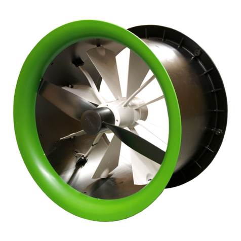
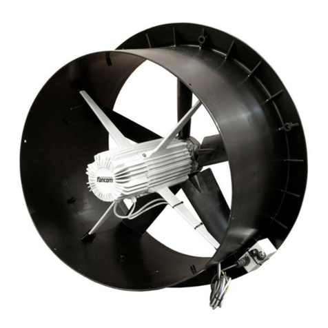
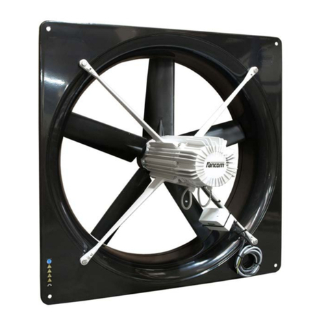
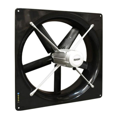
Fancom I-FAN User manual

G N D
F
gndf

N.B.: The original, authentic version of this manual is the English version produced by Fancom B.V. or one of its
daughter companies (referred to further as Fancom). Any modifications introduced to this manual by third parties
have neither been checked nor approved by Fancom. Modifications are taken by Fancom to include translations
into languages other than English and the insertion and/or deletion of text and/or illustrations to/from the original
contents. Fancom cannot be held liable for any damages, injury, guarantee claims and other claims relating to this
type of modification, in as far as these modifications result in a content that differs from the original English
version of this manual produced by Fancom. For the latest information about product installation and operation,
please contact the customer service dept. and/or the technical service dept. of the Fancom company concerned.
In spite of the care taken when compiling this manual, if you should discover any errors, please inform Fancom
B.V. in writing. Fancom B.V., PO Box 7131, 5980 AC Panningen (the Netherlands).
Copyright © 2016 Fancom B.V.
Panningen (the Netherlands)
All rights reserved. Nothing from this manual may be copied, distributed or translated into other languages, partly
or wholly, without express prior written permission from Fancom. Fancom reserves the right to modify this manual
without notice. Fancom can give no guarantee, neither implicit nor explicit, for this manual. All risks are for the
user.
This manual has been compiled with the utmost care. If, however, you should discover an error, please inform
Fancom B.V.
Art.Nr. 5911801
GB160509

Gndf
i
g
1. General introduction .................................................................................................................................. 1
1.1 How to use this manual ..................................................................................................................1
1.2 Symbols on the I-fan.......................................................................................................................1
1.3 Fancom helpdesk ...........................................................................................................................1
1.4 Safety instructions and warnings....................................................................................................2
2. Installing the I-fan....................................................................................................................................... 3
2.1 Mount the I-fan and manual control................................................................................................ 3
2.2 Connect the I-fan and manual control (MCA) .................................................................................6
2.3 Install the protective screen (optional).......................................................................................... 13
2.4 Test the I-fan ................................................................................................................................ 14
3. Using the I-fan........................................................................................................................................... 15
3.1 First use........................................................................................................................................ 15
3.2 Control options ............................................................................................................................. 15
3.3 Malfunctions ................................................................................................................................. 16
3.4 Maintenance................................................................................................................................. 16
3.5 Disposal / recycling....................................................................................................................... 16
4. Technical specifications .......................................................................................................................... 17
5. EG declaration of conformity................................................................................................................... 18

Gndf
1
g
This manual has been compiled with the utmost care. If, however, you should discover an error, please inform
Fancom B.V.
The following symbols are used in this manual:
Tips and suggestions.
Note providing recommendations and additional information.
Warning indicating damage to the product if you do not follow procedures carefully.
Warning indicating danger to humans or animals.
Electrical shock hazard. Danger to humans and animals.
Example of a practical application of the described functionality.
Calculation example.
The following symbols are used on the I-fan:
Read the documentation and safety instructions which are provided in this user manual.
Warning indicating danger to the product or danger to human or animals.
Electrical shock hazard. Danger to humans and animals.
This unit may start at any time.
Moving parts can crush and cut.
Air flow direction.
Air flow direction.
For any questions and support, please contact the local Fancom Sales & Service Center.

Gndf
2
g
Before installing and commissioning the I-fan, read the safety instructions, provisions and conditions carefully.
This paragraph contains a number of general safety instructions. In the following paragraph, a number of specific
safety instructions are included in the installation instruction. The installation of the device and remedying of any
malfunctions should be performed by a certified electrical installer according to the applicable norms. The
guarantee does not apply if this product is installed in any other way than is indicated by Fancom and if the
product's motor has been opened and changes have been made to the product.
Never install a damaged I-fan! Notify your supplier of any damages.
Parts of this product may have sharp edges. Wearing safety gloves is therefore recommended.
Ensure that the workplace is clean and dry.

Gndf
3
g
Install the I-fan and associated components as follows:
1. Mount the I-fan and manual control (MCA) (see page 3)
2. Connect the I-fan and manual control (MCA) (see page 6)
3. Install the protective screen (optional) (see page 12)
4. Test the I-fan (see page 14)
Mount the I-fan in or on a solid structure.
The direction of airflow must be from the motor to the impeller.
There must be sufficient free airflow available to cool the motor.
Take care to use suitable mounting material. The I-fan can be mounted on the wall with 4 screws.
Most I-fan units are too heavy to lift. Take the necessary precautions.
Fancom recommends mounting the I-fan as follows:
1. Disassemble the I-fan from the shroud.

Gndf
4
g
2. Make a hole in the wall. Take the dimensions of various types of I-fan into account here.
Type
A
mm
(inch)
B
mm
(inch)
Ø C
mm
(inch)
Ø D
mm
(inch)
Ø E
mm
(inch)
Ø F
mm
(inch)
G
mm
(inch)
H
mm
(inch)
I
mm
(inch)
Ø J
mm
(inch)
K
mm
(inch)
..35
445
(17.5)
405
(15.9)
8
(0.3)
346
(13.6)
365
(14.4)
380
(15)
95
(3.7)
255
(10)
15
(0.6)
127
(5)
430
(16.9)
..40
495
(19.5)
455
(17.9)
8
(0.3)
396
(15.6)
415
(16.3)
440
(17.3)
110
(4.3)
240
(9.4)
15
(0.6)
127
(5)
500
(19.7)
..45
575
(22.6)
535
(21.1)
8
(0.3)
446
(17.6)
465
(18.3)
500
(19.7)
110
(4.3)
240
(9.4)
15
(0.6)
127
(5)
560
(22)
..50
635
(25)
595
(23.4)
8
(0.3)
496
(19.5)
515
(20.3)
560
(22)
110
(4.3)
240
(9.4)
15
(0.6)
127
(5)
630
(24.8)
..56
725
(28.5)
685
(27)
8
(0.3)
556
(21.9)
575
(22.6)
615
(24.2)
110
(4.3)
240
(9.4)
15
(0.6)
127
(5)
690
(27.2)
..63
805
(31.7)
750
(29.5)
11
(0.4)
629
(24.8)
644
(25.4)
698
(27.5)
130
(5.1)
240
(9.4)
20
(0.8)
150
(5.9)
758
(29.8)
..71
850
(33.5)
810
(31.9)
14.5
(0.57)
704
(27.7)
720
(28.3)
776
(30.6)
150
(5.9)
326
(12..8)
20
(0.79)
186
(7.3)
840
(33.1)
..80
970
(38.2)
910
(35.8)
14.5
(0.6)
789
(31.1)
806
(31.7)
872
(34.3)
190
(7.5)
326
(12.8)
20
(0.8)
186
(7.3)
960.5
(37.8)
..92
1070
(42.1)
1010
(39.8)
14.5
(0.6)
902
(35.5)
914
(36)
980
(38.6)
188
(7.4)
326
(12.8)
22
(0.9)
186
(7.3)
1143
(45)
3. Secure the shroud of the I-fan to the wall.

Gndf
5
g
4. Attach the I-fan inside the I-fan shroud.
Check whether the I-fan can spin freely and that the screw fittings are on the underside of the motor.
5. Place the protective screen on the I-fan (optional).
Placement of a protective screen is necessary if the I-fan:
is within reach of animals and/or people, and
is installed at heights less than 2.7 m above the floor.
The blades of the I-fan may run backward due to external influences. To prevent the I-fan turning in the
opposite direction, it is necessary to place a shutter. If the rotating speed of the blades in the opposite
direction is higher than 25% of the I-fan unit's maximum RPM, the I-fan is no longer able to reverse the
blades to the correct direction of rotation. Then, the I-fan will not start and will sound an alarm.
Below is an example of where the connection box(es) and the manual controls may be placed.
The manual control can be connected to 1 or more fans (a maximum of 3).

Gndf
6
g
Option 1: Connecting the local manual control
1. Mount the local manual control.
2. Replace the connection box delivered by default.
Option 2: Connecting the central manual control
1. Mount to the central manual control.
2. Install a cable between the central manual control and the connection box(es) on the fan(s).
Before connecting, turn off the power and turn it back on only after the entire installation is ready.
The motor/thermal protection is already integrated in the I-fan.
Due to a higher inrush current it is possible that the current protection will be activated while power up.
The amount of I-fans, which you can connect behind a current protection, is depending on the type of
protection.
Type B: 2 I-fans
Type C: 4 I-fans
Make sure that the I-fan is well and properly grounded according to the guidelines.
Keep signal and power cables as short as possible.
Place cables preferably in a duct (separate signal cables from power supply cables).
Connect the I-fan and manual control:
Connect the I-fan connection box (see page 6)
Connect the I-fan manual operation box MCA (see page 7 )
Connect two I-fans with manual control and I/O-net (see page 9 )
Connect the power supply (see page 10 )
Set the I-fan and MCA settings:
Check the jumper settings on the MCA (see page 10)
Set the I/O address (see page 10)

Gndf
7
g
The I-fan connection box is supplied with the I-fan.

Gndf
8
g
In order to connect the regulator's analogue output, the standard connection Analogue In (3) and Gnd
(4) must be removed from the MCA inside the cover.

Gndf
9
g

Gndf
10
g
Specifications
Mounting and electric connection may be executed by qualified personnel only according to the
current standards and regulations. Please see the ID label attached to the motor for additional
information. Also see detailed specifications and fan characteristics for each type at
www.fancom.com/uk/downloads or the Fancom extranet.
By default, the jumper settings are set to overrule the I/O-net controlled I-fan units via the I/O network (1-10V). To
overrule the analogue control I-fan units, the jumper settings must be changed to 0-10V / 10-0V. Do this as
follows:
1. Replace the jumper with resistance with the jumper delivered as a standard.
2. Set the jumper to the proper position:

Gndf
11
g
Using the table on the following pages, set an I/O address with the dipswitches on the I-fan motor.
In an I/O network, all I-fan units must have a unique address.
Analogue control
I/O
address
DIP 1
DIP 2
DIP 3
DIP 4
DIP 5
DIP 6
DIP 7
DIP 8
0
ON
ON
ON
ON
ON
ON: 10-0V dc
(10V=0%,
0V=100%)
OFF: 0-10V dc
(0V=0%,
10V=100%)
ON
N/A (ON/OFF)

Gndf
12
g
Digital control
I/O
address
DIP 1
DIP 2
DIP 3
DIP 4
DIP 5
DIP 6
DIP 7
DIP 8
1
OFF
ON
ON
ON
ON
ON: 10-0V dc
(10V=0%,
0V=100%)
OFF: 0-10V dc
(0V=0%,
10V=100%)
ON
ON: 50%
OFF: 100%
2
ON
OFF
ON
ON
ON
3
OFF
OFF
ON
ON
ON
4
ON
ON
OFF
ON
ON
5
OFF
ON
OFF
ON
ON
6
ON
OFF
OFF
ON
ON
7
OFF
OFF
OFF
ON
ON
8
ON
ON
ON
OFF
ON
9
OFF
ON
ON
OFF
ON
10
ON
OFF
ON
OFF
ON
11
OFF
OFF
ON
OFF
ON
12
ON
ON
OFF
OFF
ON
13
OFF
ON
OFF
OFF
ON
14
ON
OFF
OFF
OFF
ON
15
OFF
OFF
OFF
OFF
ON
16
ON
ON
ON
ON
OFF
17
OFF
ON
ON
ON
OFF
18
ON
OFF
ON
ON
OFF
19
OFF
OFF
ON
ON
OFF
20
ON
ON
OFF
ON
OFF
21
OFF
ON
OFF
ON
OFF
22
ON
OFF
OFF
ON
OFF
23
OFF
OFF
OFF
ON
OFF
24
ON
ON
ON
OFF
OFF
25
OFF
ON
ON
OFF
OFF
26
ON
OFF
ON
OFF
OFF
27
OFF
OFF
ON
OFF
OFF
28
ON
ON
OFF
OFF
OFF
29
OFF
ON
OFF
OFF
OFF
30
ON
OFF
OFF
OFF
OFF
31
OFF
OFF
OFF
OFF
OFF

Gndf
13
g
Remove power from the I-fan before mounting the protective screen.
Make sure that the impeller is not turning.
Install the protective screen as follows:
Air inlet side
Install the protective screen on the I-fan and secure it as shown in the illustration below.

Gndf
14
g
Air outlet side
1. Hold the protective screen up to the I-fan and trace the three drill holes.
2. Drill the three holes with a ø5mm bit.
3. Place the protective screen on the I-fan and fix the protective screen with a M5 x 30 bolt.
1. Check whether the I-fan has been connected correctly.
2. Check whether the I-fan works optimally.
Do not touch any of the I-fan moving parts.

Gndf
15
g
Do not touch any of the I-fan moving parts.
Fancom advises to leave the I-fan on for about 6 hours after installation, to let it run in.
Analogue control (0-10V;10-0V)
Digital control (I/O network)
If the I-fan is controlled via the I/O network, this can be
bridged with a manual control via the -10V input. In this
case, both the I/O network and the 0-10V are connected.
A manual control has the following positions:
AUT : (0-1V) automatic regulation via the I/O network
OFF : (1-1.5V)
MAN : (1.5-10V) manual regulation (continuous) via
manual control

Gndf
16
g
Analogue and digital
When overloaded, the I-fan will adjust itself back on the basis of maximum power. If the RPM is lower than
93% of the maximum RPM, an alarm will sound.
For other malfunctions, the I-fan will start itself up again independently after a short while. If the motor does
not start up then, the alarm relay will be switched off. If the I-fan no longer starts independently, the I-fan
must be removed from power for at least 30 seconds and then be started up again.
Digital
If I/O communication is interrupted, the last set value remains active.
Turning the power supply on and off without I/O communication will activate the predefined setting of
dipswitch 8 (ON=50%, OFF=100%, see also page 10).
The I-fan requires no specific maintenance. Fancom recommends that your installation technician inspects the
complete climate installation, of which the I-fan is a component, every half-year.
Inspect the I-fan periodically for any damages. Notify your installation technician immediately of any
damages. A damaged I-fan is unsafe!
Check the I-fan for proper functioning regularly.
There must always be power to the I-fan. This prevents the formation of condensation in the I-fan.
When the mains power is interrupted, the alarm relay is also interrupted.
The I-fan may be cleaned wet, but consider the following:
Do not use a high pressure hose or aim at motor seals or openings at close range.
The fan should be turning. This makes for a better seal at the shaft ends and prevents water flowing into
the motor. It is recommended that the fan turns at 50%. If so, water will be discharged faster by the
airflow.
This fan has protection class IP66.
After cleaning the I-fan, it should run at 100% rpm for at least 30 minutes to remove all dampness.
When disposing the I-fan please comply with all relevant requirements and regulations applicable in your country.

Gndf
17
g
See the ID label on the motor for additional information. Also see detailed specifications and fan
characteristics for each type at www.fancom.com/uk/downloads or the Fancom extranet.
Table of contents
Languages:
Other Fancom Fan manuals