Fancy Foam Models Rans S-7 Courier User manual

Rev. 1.0, 3-31-2015
Fancy Foam Models, LLC
635 Laramie Cir. Maize, Ks. 67101
.fancyfoam.com
Assembly Instructions for the Rans S-7 Courier.
Recommended Electronics and motors:
Propeller: 10x5 electric
Motor: 2810-1100kv or any equivalent motor
Speed control: 20-30 amp.
Battery: 1300mah, 3 cell, 20C rated Li-Po or
equivalent.
Receiver: 5-8 channel (see radio setup).
Servos: (6) HXT 900.
Servo Extensions: (4) 30cm long
Disclaimer: Fancy Foam Models has done
everything we can to caution and inform the end
user regarding the use of Lithium polymer battery
technology. We are in no way responsible for any
damage that may be caused by these batteries.
Please read, understand and follow all instructions
for the charger and batteries. Failure to use this
battery technology properly can result in the ris of
fire. If you are not comfortable with this
technology, return the batteries pac s and it to us
for a refund. By building the it and using the
batteries, you accept full responsibility for the
safety of these batteries.
Recommended building methods and glues:
Much of the construction of this model is done by
laying the parts on a flat table. It is strongly
recommended that you put ax paper do n on the
surface first so any excess glue doesn’t soak through
the foam and glue the parts to the table. For all
assembly, use “Foam-Tac” contact adhesive. The
hinges are also done ith Foam-Tac, see our video on
the eb site. Hot glue can be used to attach the servos
and control horns.
Painting:
It is easiest to paint the parts before assembly. Card
stock can be used to make templates for stripes,
checkers, ect... Epp does is not affected much by
solvents so Krylon, Testors and airbrush paints can be
used.
Wing assembly:
Start by gluing the t o ing halves together. The
Foam-Tac glue is a contact adhesive. Apply glue to
both sides of the joint and spread to a thin layer. Allo
to dry a minute or so and press the parts together.
Allo 10 minutes for a full cure.
There are marks on each ing tip 2-3/4” back from the
leading edge. Align a strait edge ith these marks and
using a sharp razor blade cut a 1/8” deep slot 40” long
on the top and bottom of the ing. Put a small bead of
glue on the slot and push one of the carbon rod spars
through the glue and into the slot. Spread any
remaining glue into the foam over the spar. When the
glue is dry, repeat for the other side.
1

Cut a 6” long slot 1/2” for ard of the hinge line on the
bottom of the ing and glue in the 6” long carbon rod.
Servo installation:
Cut slits about ¼” deep in the foam from servo cutouts
to the center as sho n for the servo ires. Glue the
servos into the cutouts. Push the servo ires into the
slits so they are buried in the foam. The flap servos ill
need servo extensions or a reversing Y-harness
installed. There is a pre-cut pocket in the ing for the
connectors.
Cut a 1/2” slit in the ailerons and flaps in line ith the
servo arm for the control horn tab. The holes in the
control horns should be directly above the hinge line.
Glue the control horns in place. Cut four pieces of the
included push rod ire and bend a Z-bend on one end.
Set the servo arm centered and the control surface
neutral. *(For a non computer radio see the radio setup
section at the end for suggested servo arm angle.)
Fuslage construction:
Glue the carbon tube into the slot in the bottom of the
elevator and set aside to dry.
Glue the top rear fuselage piece to one of the side
fuselage pieces and then the other. The top piece ill
be bet een the side pieces not on top of them. Take
care that the t o side pieces are aligned ith each
other.
2
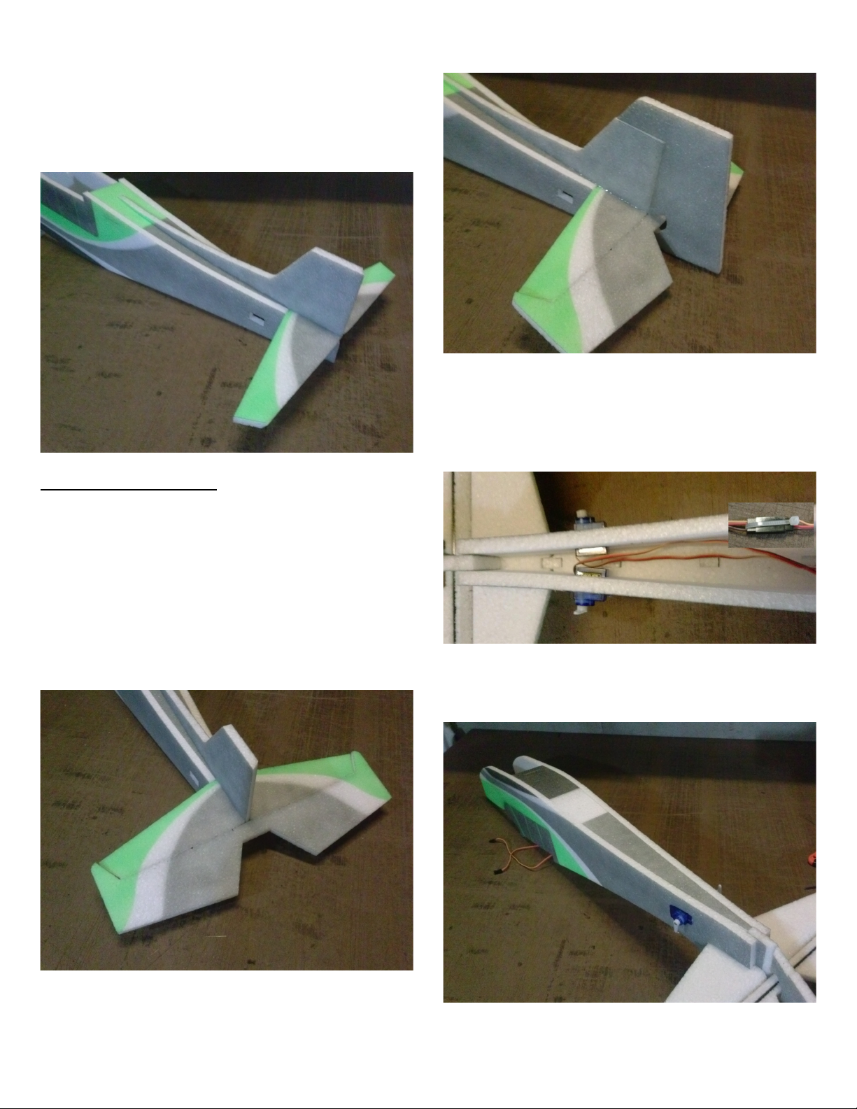
Glue the horizontal stabilizer in position on the vertical
stabilizer. Glue the vertical/horizontal stabilizer to the
fuselage. The lo er section goes bet een the fuselage
sides and overlaps them 3/4”. Before the glue has
dried, verify that the horizontal stabilizer is square to
the fuselage looking at it from the top and the back.
Control surface hinging:
The glue hinge is done ith Foam-Tac glue by
applying a small bead of glue to each side of the edge
of the bevel. Spread this glue into the foam on and
around the edge of the bevel. Let the glue tack up for
about a minute and then press the parts together. Let
the glue dry for about 10 minutes and then flex the
joint several times full deflection to loosen the hinge.
Hinge the elevator to the horizontal stabilizer.
Hinge the rudder to the vertical stabilizer.
Glue the tail servos in the cutouts in the tail. Add the
servo extensions. You can use heavy thread or a zip tie
to tie the connectors together so they do not come
apart.
Glue the lo er fuselage in place bet een the fuselage
sides.
3

Glue the tail heel bracket to the rear of the fuselage. I
tack it in place ith Foam-Tac and then go around the
outside edge ith hot glue. The plastic tube glues to
the rudder and allo s the metal rod to move in and out
as the rudder goes side to side.
Mount the motor to the fire all feed the motor ires
through a cooling hole and hook up the speed control
(ESC). This is a good time to test the motor direction.
DO NOT do this ith a prop attached.
If the motor spins the rong direction, s ap any t o of
the three motor ires and this ill reverse the motor.
Glue the fire all into the slots in the fuselage sides.
Glue the foam doubler onto the for ard lo er fuselage
so the slots line up. Glue together the remaining foam
parts that make up the battery tray and glue them to the
doubler. Smear Foam-Tac on the top surface of the
battery tray and allo it to fully dry. Stick a piece of
velcro to the top of the tray. The glue on the surface
ill help the velcro stick better.
Glue the for ard lo er fuselage in place.
4

Route the tail servo ires though the opening in the
fuselage former. Glue the former in place at the rear of
the ing opening.
Mount the ESC and receiver to the side of the fuselage.
The top nose piece glues in place bet een the fuselage
sides. The back edge should line up ith the notch in
the indo area of the fuselage sides.
Glue the latch assembly in place on the battery hatch.
Place the ing on the fuselage and the battery hatch in
place and check the fit. Using Foam-Tac hinge the
battery hatch to the rear edge of the top nose piece.
When the hinge glue is dry, glue the ing to the top of
the fuselage. Make sure that the ing is square to the
fuselage from the top and the front.
5
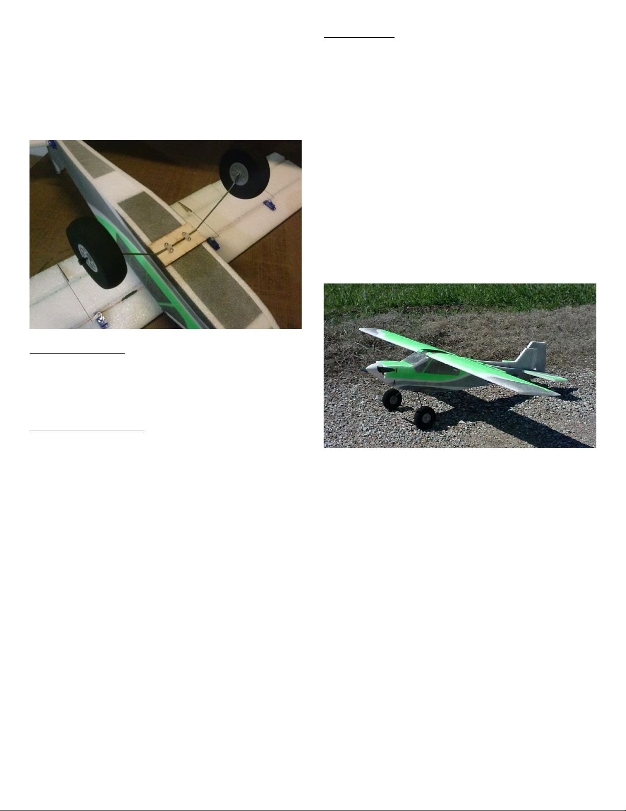
Glue the ply ood plate to the bottom of the fuselage
ith the slot aligned ith the slot in the bottom piece. I
add hot glue around the edges of the ply ood to better
secure it.
Insert the landing gear ire into the slot and secure it
ith the plastic straps and 4 of the scre s that came
ith your servos. Install the heels and the heels
collars.
Center of Gravity:
The battery can be moved on the tray to adjust the CG
to the recommended 2” behind the leading edge of the
ing.
Radio setup for wing:
Computer radio ith correct receiver for a 4 servo
ing can be used or 5 ch receiver ith Y-harness for
ailerons and reversing Y-harness for flaps. See your
radio's instructions for specific information.
For a computer radio, each of the ing servos ill plug
into a separate channel on the receiver. 2 outer servos
assigned to aileron and the 2 inner servos assigned to
flaps. For improved roll rate the ailerons can be mixed
to the flaps so the flaps move ith the ailerons. We do
not advise setting up the ailerons to function as flaps as
this ill increase the chance of ing stall.
For a 5 ch radio setup, both aileron servos ill plug
into a standard Y-harness and then into the aileron
channel. The aileron servo arm should be angled
for ard about 30 degrees. This ill provide
mechanical aileron differential hich ill correct any
adverse ya and help the plane roll ith out ya ing.
The flap servos plug into a reversing Y-harness so they
ill move the same direction and then into the flap
channel.
Flight set-up:
Use your computer radio to set the final sub-trims,
exponential and dual rates. Double check the control
directions before your first flight.
We have found that a 1300 mah 3s battery is perfect for
giving good flight times and plenty of po er as ell as
a proper CG.
The suggested control thro s are +/- 30 degrees for
high rates and +/- 20 degrees for lo rates.
Flaps can be set for any here from 10 deg to 45 deg.
Setting up Aileron differential here the ailerons ill
move about 40% more up than do n ill correct any
adverse ya and help the plane roll ith out ya ing.
We hope you enjoy your airplane.
Thank You,
Mike & Niki Bailey
Fancy Foam Models
6
Other Fancy Foam Models Aircraft manuals


