F&J DF-75L-Li User manual

Rev.: 04 November 2013
F:\MARKETING\TECHNICAL MANUALS\Air Samplers\DF Battery TECH MANUALS\DF-75 LPM SERIES.doc
F&J SPECIALTY PRODUCTS, INC.
The Nucleus of Quality Air Monitoring Programs
EMERGENCY RESPONSE AIR SAMPLING
SYSTEM
Digital Flowmeter Technology 75 LPM DF Series
TECHNICAL MANUAL
DF-75L-Li
DF-75L-AC

F:\MARKETING\TECHNICAL MANUALS\Air Samplers\DF Battery TECH MANUALS\DF-75 LPM SERIES.doc
Tel: (352) 680-1177 / Fax: (352) 680-1454 / Email: fandj@fjspecialty.com
2
TABLE OF CONTENTS
Page
General Description and Specifications
3 – 6
Hazard Warning Labels
7
Installation Instructions
8
Operating Features and Instructions
9 – 21
Filter Holders
Sensors
Corrections to Reference T and P
Low Voltage Limiting System Description
22
Calibration Instructions
23 – 25
Maintenance Instructions
26
Spare Parts List
27 – 28
Electrical Wiring Diagrams
29 – 30
Warranty Information and Limitation of Liability
31
Service Information
32
Contact Information
33
Copyright © 2005 F&J SPECIALTY PRODUCTS, INC.
This operator manual and information contained herein is proprietary to
F&J SPECIALTY PRODUCTS, INC. and shall not be reproduced, copied in whole or in part,
adapted or disseminated without the express written consent of
F&J SPECIALTY PRODUCTS, INC.
F:\MARKETING\TECHNICAL MANUALS\Air Samplers\DF Battery TECH MANUALS\DF-75 LPM SERIES.doc
Tel: (352) 680-1177 / Fax: (352) 680-1454 / Email: fandj@fjspecialty.com
3
EMERGENCY RESPONSE SAMPLING SYSTEM
—Digital Flowmeter Technology —
F&J Model DF-75L-Li
GENERAL DESCRIPTION:
F&J Model DF-75L-Li is a lightweight, small footprint, DC voltage powered air sampling system operable
from (1) on-board 14.8 VDC; 15.6 Ah Lithium ion battery, (2) line power, or (3) automobile cigarette lighter
socket.
The DF-75L-Li is well suited for emergency response sampling activities where users do not know whether
line power will be available and for alternative energy power source applications when line power is not
available.
The automatic flow control feature with the F&J Digital Flowmeter technology provides maximum
flexibility for emergency response sampling responsibilities. The set flowrate is maintained automatically in
case of dust loading and does not require operator attention.
Typical flow range is 30-75 SLPM (1.1 -2.6 SCFM).
Rev.: 20 May 2008
NOTABLE FEATURES:
State-of-the-Art Electronics
Operating Modes
— Line Power (110VAC – 250VAC)
— On-Board Batteries
— Automobile Cigarette Lighter
Long-lasting Lithium ion battery
Battery Charging Circuit operable from Line Power
Input
Lightweight — ~17.5 lbs. (8.0 kg)
Maximum Flow: 65 to 75 LPM; typical
Bright LED Display
Automatic Flow Control Feature
Flowrate and Volume totalizations displayed are
corrected to a factory settable Reference
Temperature and Pressure (4 options available)
Auto shut-off on time or volume
Battery Life Indicator
F:\MARKETING\TECHNICAL MANUALS\Air Samplers\DF Battery TECH MANUALS\DF-75 LPM SERIES.doc
Tel: (352) 680-1177 / Fax: (352) 680-1454 / Email: fandj@fjspecialty.com
4
DF-75L-Li Battery Powered Air Sampler Specifications
Pump Type: Dual diaphragm high efficiency
Maximum Flowrate:
75 LPM – Typical w/47 mm FP47M glass fiber media
100 LPM – Free air flow capacity
Power Source:
Internal –
14.8 VDC Battery Pack
Lithium Ion; 15.6 Ah
External –
Line Power; 110VAC or 250VAC
Automobile Cigarette Lighter – 12VDC
Battery Charging System:
Internal System which charges from line Power.
Operating Time on Batteries:
8 - 10 hours @ 56 LPM w/FP-47M
glass fiber media
Current Draw: 3 A maximum
Filter Holder Fitting: 3/8 FNPT quick disconnect
Handle: Durable metal
Weight: 15.3 lbs. (7 kg)
Dimensions: 8”×9”×12” (20 × 23 × 30 cm)
Display: Bright LED (6 character; 1.2 cm H)
Elapsed Time: DD:HH:MM up to 168 hours
Flow Control:
Adjustable from keypad between 30-75 LPM
Flow Accuracy: ±4.0% of Full Scale
Factory Settable Reference T and P
Classical STP 0ºC, 1 ATM
Normal T and P 20ºC, 1 ATM
Modified Normal T and P 70ºF, 1 ATM
Standard Ambient T and P 25ºC, 1 ATM
OPTIONS:
Data Storage Device (P/N: 232FCDSD)
1 GB Secure Digital Card (P/N: 372239)
Flash card Reader (P/N: SDDR-199-A20)
Standard Combination Filter Holders Available:
FILTER
HOLDER
MODEL
CHARCOAL
CARTRIDGE
DIMENSIONS
PARTICULATE
PAPER
DIAMETER
FJ-05P
F&J Model B
2” or 50 mm
FJ-21P
F&J Model C
2” or 50 mm
FJ-35P
F&J Model B
47 mm
FJ-46P
F&J Model C
47 mm
FJ-51P
F&J Model M
2” or 50 mm
FJ-53P
F&J Model M
47 mm
Available Engineering Units for Flow and Volume:
sccm/ scc
SLPM / SLP
SCFM / SCF
SCMH / SCM
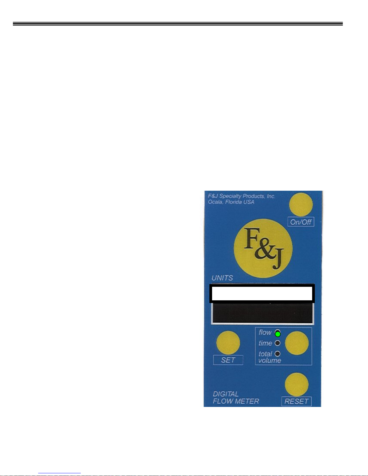
Digital Flowmeter Keypad/Display
Flow /Volume: SLPM/SL
28.5

F:\MARKETING\TECHNICAL MANUALS\Air Samplers\DF Battery TECH MANUALS\DF-75 LPM SERIES.doc
Tel: (352) 680-1177 / Fax: (352) 680-1454 / Email: fandj@fjspecialty.com
5
EMERGENCY RESPONSE SAMPLING SYSTEM
—Digital Flowmeter Technology —
F&J Model DF-75L-AC
GENERAL DESCRIPTION:
F&J Model DF
-75L-AC is a lightweight, small footprint, DC voltage powered air sampling system
operable from (1) on
-board 14.8 VDC; 15.6 Ah Lithium ion batteries, (2) a 12-15 VDC power source
such as solar panels or other alternative energy sources.
The DF
-75L-AC is well suited for alternative energy air sampling activities where users do not know
whether line power will be available
and for alternative energy power source applications when line
power is not available. The unit may be operated from solar po
wer or wind power source through
either the AC input or DC input.
The automatic flow control feature with the F&J Digital Flowmeter technology provides maximum
flexibility for emergency response sampling responsibilities. The set flowrate is maintained
au
tomatically in case of dust loading and does not require operator attention.
Typical flow range is 30
-75 SLPM (1.1 -2.6 SCFM).
Rev.: 21 May 2008
NOTABLE FEATURES:
State-of-the-Art Electronics
Operating Modes
— Line Power (110VAC – 250VAC)
— Automobile Cigarette Lighter
Lightweight — ~11 lbs. (52,9 kg)
Maximum Flow: 65 to 75 LPM; typical
Bright LED Display
Automatic Flow Control Feature
Flowrate and Volume totalizations displayed are
corrected to a factory settable Reference Temperature
and Pressure (4 options available)
Auto shut-off on time or volume
F:\MARKETING\TECHNICAL MANUALS\Air Samplers\DF Battery TECH MANUALS\DF-75 LPM SERIES.doc
Tel: (352) 680-1177 / Fax: (352) 680-1454 / Email: fandj@fjspecialty.com
6
DF-75L-AC AC/DC Powered Air Sampler Specifications
Pump Type: Dual diaphragm high efficiency
Maximum Flowrate:
75 LPM
– Typical w/47 mm FP47M glass fiber
media
100 LPM
– Free air flow capacity
Power Source:
Line Power; 110VAC or 250VAC
Automobile Cigarette Lighter – 12VDC
Current Draw:
4 A maximum
Filter Holder Fitting:
3/8 FNPT quick disconnect
Handle:
Durable metal
Weight:
11 lbs. (5 kg)
Dimensions:
8”×9”×12” (20 × 23 × 30 cm)
Operating Temperature Ranges:
0ºF to 122ºF (-18ºC to 50ºC)
Display:
Bright LED (6 character; 1.2 cm H)
Elapsed Time:
DD:HH:MM up to 168 hours
Flow Control:
Adjustable from keypad between 30
-75 LPM
Flow Accuracy:
± 4.0% of Full Scale
Factory Settable Reference T and P
Classical STP 0ºC, 1 ATM
Normal T and P 20ºC, 1 ATM
Modified Normal T and P 70ºF, 1 ATM
Standard Ambient T and P 25ºC, 1 ATM
OPTIONS:
Data Storage Device (P/N: 232FCDSD)
1 GB Secure Digital Card (P/N: 372239)
Flash card Reader (P/N: SDDR-199-A20)
Standard Combination Filter Holders Available:
FILTER
HOLDER
MODEL
CHARCOAL
CARTRIDGE
DIMENSIONS
PARTICULATE
PAPER
DIAMETER
FJ-05P
F&J Model B
2” or 50 mm
FJ-21P
F&J Model C
2” or 50 mm
FJ-35P
F&J Model B
47 mm
FJ-46P
F&J Model C
47 mm
FJ-51P
F&J Model M
2” or 50 mm
FJ-53P
F&J Model M
47 mm
Available Engineering Units for Flow and Volume:
sccm/ scc
SLPM / SLP
SCFM / SCF
SCMH / SCM
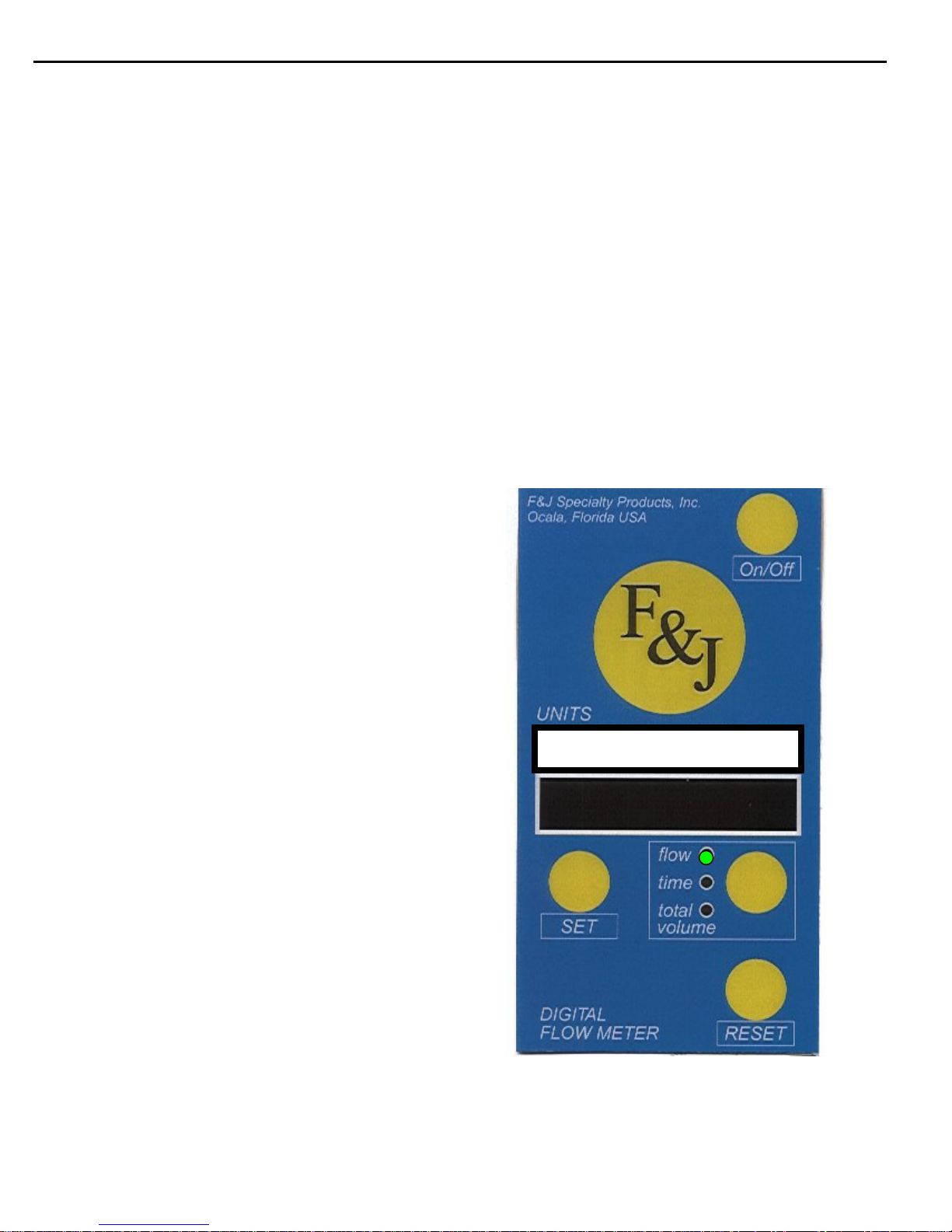
Digital Flowmeter Keypad/Display
Flow /Volume: SLPM/SL
60.0
F:\MARKETING\TECHNICAL MANUALS\Air Samplers\DF Battery TECH MANUALS\DF-75 LPM SERIES.doc
Tel: (352) 680-1177 / Fax: (352) 680-1454 / Email: fandj@fjspecialty.com
7
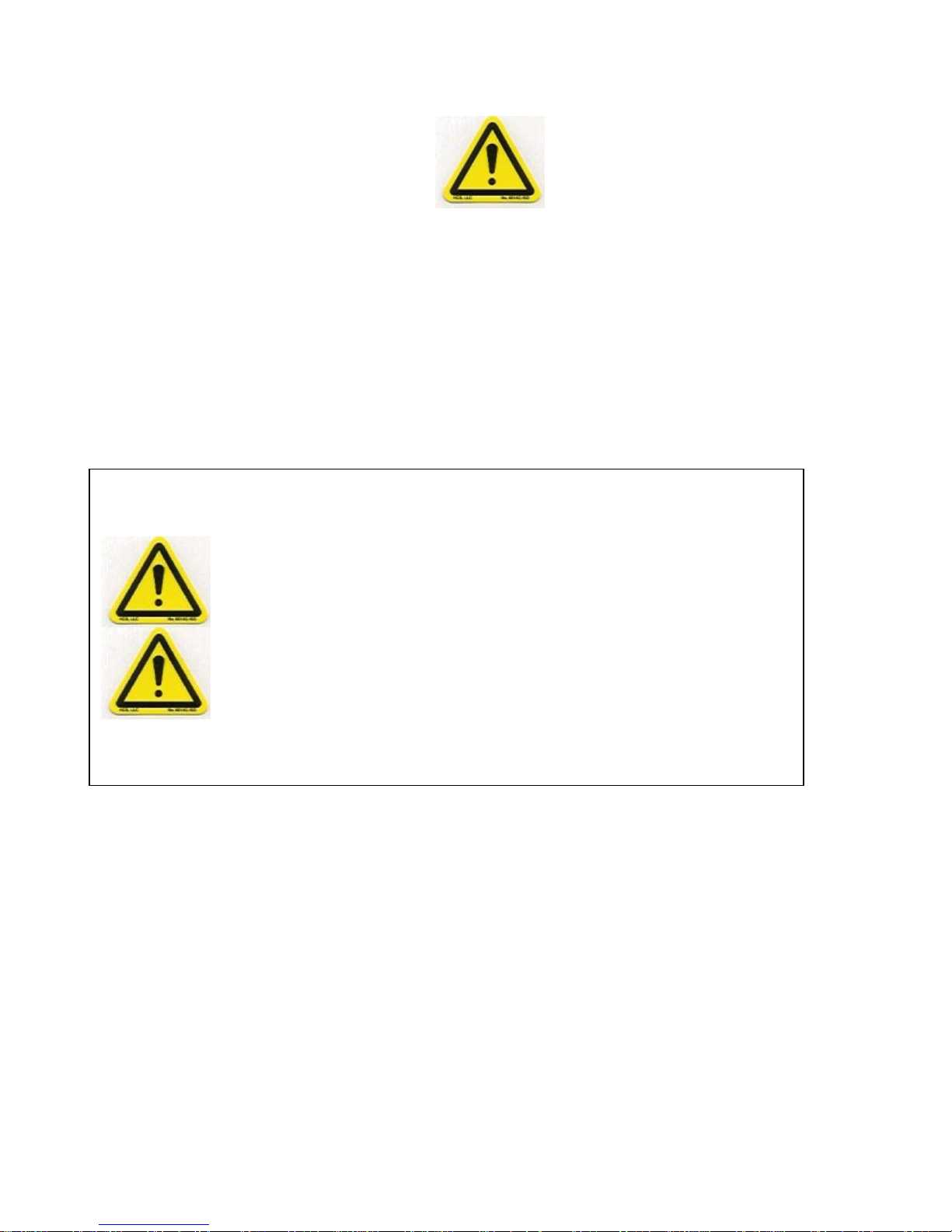
HAZARD ALERT LABELS
This is the hazard alert symbol:
This symbol is utilized throughout the manual to notify the user or maintenance
personnel to proceed with caution.
When you see this symbol, be aware that personal injury or property damage is possible.
The hazard is explained in text following the symbol.
Read this information carefully before proceedings.
The following is an explanation of the two (2) different types of hazards:
Severe personal injury or death can
occur if hazard is ignored.
Minor injury or property damage can
occur if hazard is ignored.
WARNING
CAUTION

F:\MARKETING\TECHNICAL MANUALS\Air Samplers\DF Battery TECH MANUALS\DF-75 LPM SERIES.doc
Tel: (352) 680-1177 / Fax: (352) 680-1454 / Email: fandj@fjspecialty.com
8
Installation Instructions for DF Battery Air Samplers
The 75 LPM DF Battery Emergency Response Air Sampling System has been shipped in a corrugated
box(es). Open each container, remove the air sampler from the shipping container and perform the
following inspections:
1. Confirm that the instrument calibration documentation arrived with the unit.
2. Confirm that the serial number and model number on the instrument Manufacturer’s
Data Plate matches the information stated on the calibration documents.
3. Confirm the line power requirements stated on the Manufacturer’s Data Plate matches
the line power available.
4. Confirm that the instrument as received has no visible damage or loose components.
Particularly check for loose screws and that no observable damage to the air sampler
has occurred in transit.
5. Plug the air sampler into the local line power using the power cord provided after
confirmation of line power compatibility in step 3 above. If a local style plug is
required, install the plug in accordance with local electrical code prior to proceeding.
Plug the unit into a grounded receptacle.
NOTE:F&J recommends that the Air Sampler is operated to the point of discharge,
followed by a complete charge on a once per month frequency.
6. Refer to the operating instructions part of this manual titled “OPERATING
FEATURES and INSTRUCTIONS” for instructions on how to operate the instrument.
7. Install the filter media to be utilized with the instrument.
8. Turn on the DFM electronics by pressing the On/Off button on the DFM keypad. The
button is located in the upper-right corner of the DFM.
9. After referring to the operating instructions portion of this manual and mastering the
basic operating techniques, confirm the unit air flow sensors are functioning properly by
setting various flow rates, then viewing the DFM display.
The instrument may now be placed in service. Please refer to the operating instruction portion of this
manual for details on the operation of these instruments.
CAUTION
WARNING
F:\MARKETING\TECHNICAL MANUALS\Air Samplers\DF Battery TECH MANUALS\DF-75 LPM SERIES.doc
Tel: (352) 680-1177 / Fax: (352) 680-1454 / Email: fandj@fjspecialty.com
9
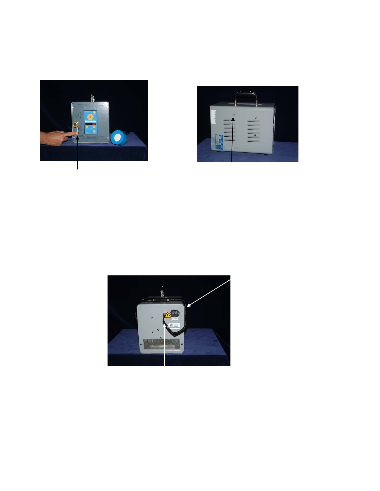
OPERATING FEATURES and INSTRUCTIONS
The 75 LPM DF Battery Series air samplers have all the operational components conveniently
accessible to the user. Model DF-75L-AC and DF-75L-Li air sampler’s pertinent components are
illustrated below in Figure 1 through Figure 3.
Battery Capacity Indicator
External DC Power Input
AC Receptacle
RS 232 Port
Figure 2
Figure 1
DF-75L-AC and DF-75L-Li
Figure 3
DF-75L-Li and DF-75L-AC Rear View

F:\MARKETING\TECHNICAL MANUALS\Air Samplers\DF Battery TECH MANUALS\DF-75 LPM SERIES.doc
Tel: (352) 680-1177 / Fax: (352) 680-1454 / Email: fandj@fjspecialty.com
10
OPERATING FEATURES and INSTRUCTIONS (Cont.)
POWER SOURCE
The 75 LPM DF Battery air samplers can be powered from any of the following power sources:
1. A 110VAC or 230VAC line power via the three-prong electrical connector at the rear of the
enclosure. This line power is converted to 12 VDC power through a universal transformer
accepting AC line voltage from 100VAC to 250VAC.
2. A 12 VDC Automobile Cigarette Lighter or Accessory socket. This connection is located at
the rear of the air sampler.
3. An internal 12 VDC lead acid or 14.8 VDC Lithium ion battery when external AC or DC
power is not available. The AC line voltage will charge the internal lead acid or Lithium ion
battery.
ON-OFF SWITCH
The ON/OFF switch is on the Digital Flowmeter. This enables the user to turn the air sampler on and
off with one switch.
FUSES
The 75 LPM DF Battery Series Units have a 3 amp fuse in the AC socket (PN CEINF).
ELECTRICAL FLOW CONTROL
The 75 LPM DF Battery air samplers utilize motor speed flow control. This is adjusted in the setup
process of the Digital Flowmeter (DFM).
FLOW MEASUREMENT
Flow is indicated on the LED display when the UNITS green LED is in the FLOW position on the
DFM. Various flowmeter ranges and flow measurement units are selectable at the time of purchase
since they are set at the factory.
DIGITAL FLOWMETER CALIBRATION
The Digital Flowmeter calibration accuracy should be verified on a once per year frequency absent any
suspected or observed damage to the unit. A factory calibration is recommended at the time of known
or suspected damage to the unit.
PUMP CAPACITY
The maximum sampling flow rate achievable by the 75 LPM DF Battery Series air samplers is
dependent upon the flow restriction characteristics of the charcoal filter and/or particulate filter
utilized. In general, coarser mesh charcoal, larger diameter filter paper and/or more porous filter paper
will enable one to achieve higher flow rates. The end user must determine the specific objectives of the
sampling application and utilize the proper combination of filters and flow rate to achieve the desired
objectives.
BATTERY CAPACITY INDICATOR
There are 5 LEDs under the quick disconnect that indicate the percentage of battery charge available.
When the white button under the column of LEDs is pressed, an LED will illuminate. The 5 LEDs
indicate 100%, 75%, 50%, 25% or 0% battery capacity.
BATTERY CHARGING INDICATOR
The red LED under the Battery Capacity Indicator illuminates when the battery is charging.

F:\MARKETING\TECHNICAL MANUALS\Air Samplers\DF Battery TECH MANUALS\DF-75 LPM SERIES.doc
Tel: (352) 680-1177 / Fax: (352) 680-1454 / Email: fandj@fjspecialty.com
11
OPERATING FEATURES and INSTRUCTIONS (Cont.)
The Digital Flowmeter:
The Digital Flowmeter (DFM) is the control panel of the air sampler. Through the DFM, the operator
activates the features of the instrument, as well as monitor the flow parameters.
The keypad for the DFM series of air samplers has the following features:
1. Four keypad buttons
2. 6 character LED display of 0.5 inch (1.2 cm) height
3. Label indicating the engineering units for the flow represented by the digits
displayed by the LED
These engineering units are factory set and can not be changed in the field.
Flow / Volume: SLPM / SL
UNITS

F:\MARKETING\TECHNICAL MANUALS\Air Samplers\DF Battery TECH MANUALS\DF-75 LPM SERIES.doc
Tel: (352) 680-1177 / Fax: (352) 680-1454 / Email: fandj@fjspecialty.com
12
OPERATING FEATURES and INSTRUCTIONS (Cont.)
Keypad Buttons and Their Functions
ON-OFF: The ON-OFF button is located in the upper right corner of the DFM
module.
Pressing the ON-OFF button while the air sampler is connected to line
power but not running will place the unit in standby mode. Power is
enabled to the DFM.
RESET: The RESET button is located in the lower right hand corner of the DFM
module.
The RESET button is utilized to start and stop the air sampler motor, to
commence a sampling event or to terminate a sampling event, when
manual on/off is enabled.
Note: The DFM must be in flow mode for Reset to function as a pump
On-Off button.
The accumulated elapsed time and accumulated total volume are not
automatically reset to zero when the air sampler is started. This feature
allows the operator to temporarily suspend sampling for maintenance, to
implement a different set up, or to enable different features.
Note: In Time display mode, the RESET button zeros the elapsed time.
In Total Volume display mode, the RESET button zeros total volume.
UNITS: The UNITS button is located on the right side of the DFM module.
Pressing the UNITS button enables an operator to display flow, elapsed
time, or total volume by advancing the green LED to the different
positions.
The default position of the green LED is the Flow position upon start up or return to power after a
power outage.
Pressing the UNITS button once moves to the Elapsed Time (time) position displayed
in HHH:MM (Hours-Minutes mode).
Pressing the UNITS button when the green LED is in the time position advances to the
total volume position.
NOTE: Do not assume that total volume and elapsed time are zero when flow is zero.
Check both the elapsed time and total volume values prior to commencing a sample
event.

F:\MARKETING\TECHNICAL MANUALS\Air Samplers\DF Battery TECH MANUALS\DF-75 LPM SERIES.doc
Tel: (352) 680-1177 / Fax: (352) 680-1454 / Email: fandj@fjspecialty.com
13
OPERATING FEATURES and INSTRUCTIONS (Cont.)
In Time display mode, the colon (:) blinks when the motor is turned on and is continuously illuminated
when the air sampler is in stand-by condition. The blinking colon also indicates that the elapsed time
accumulation is in progress.
SET: The SET button is located on the left side of the DFM. The SET button is
utilized to set, enable, or disable one or more of the available features
listed below:
Automatic Shut-Off on time
Automatic Shut-Off on volume
Activation of Flow Control
Selection of Data Frequency
Selection of Actual or Standard Flow
Engineering Units
The engineering units for flow and volume are listed on the label above the LED display. The
engineering units, selectable by the user at the time of purchase, are as follows:
Flow Volume
SCFM SCF
SLPM SL
SCMH SCM
sccm scc
A user can not switch engineering units in the field. The Digital Flowmeter electronic unit must be
returned to the factory to change the engineering units and to recalibrate the system sensors.

F:\MARKETING\TECHNICAL MANUALS\Air Samplers\DF Battery TECH MANUALS\DF-75 LPM SERIES.doc
Tel: (352) 680-1177 / Fax: (352) 680-1454 / Email: fandj@fjspecialty.com
14
RS232 Communications Port
General
Most models of the Digital Flowmeter have the RS232 communications port enabled.
The DFM transmits a fixed length, comma delimited ASCII string of data. The data string is comprised
of the following parameters in its general format.
dd.hh.mm,ttt.t.F,bb.bb.In Hg, dd.dd In H2O (aaaaaaaaa or ccccccccc), uuuuu,
[….],vvvvvvvvv,UUU
Where:
dd,hh:mm - elapsed time in day.hour: minute format
ttt.t. T - temperature [ºF] or [ºC]
bb.bb. InHg - barometric (inlet) pressure [InHg] or [mm Hg]
dd.dd InH2O - differential pressure [InH2O] or [mm Hg]
aaaaaaaaa - ambient flow with 3, 2 or 1 decimal digit resolution up to
99999, or in x.xxxEyyy format for larger numbers. This
format ensures the possible best resolution even for large
values. Ambient flow has an “a” as prefix
ccccccccc - corrected flow (same format as for the ambient flow) but
it has an “S” prefix
uuuuu - Engineering Unit for flow: SCFM, SLPM, sccm or
SCMH or aCFM, aLPM, accm or aCMH if ambient flow
is selected
[…] - optional values for Totalizer model
vvvvvvvvv - Total volume (same format as for the ambientflow)
UUU - Engineering Unit for total volume: SCF, SL, scc or SCM
or aCFM, aL, acc or aCMH
The engineering units change according to customer selection. The […] data (total flow and
engineering units are sent out when the Totalizer option is enabled.)
An example of a data string utilizing English units is illustrated below.
0.00:21,77.2 F, 30.74 InHg, 2.98 In H2O, 2.72SCFM, 50.21SCF
Data transmission frequency is operator selectable at once per second, once per minute, once per 6
minutes, and once per hour from the serial port.

F:\MARKETING\TECHNICAL MANUALS\Air Samplers\DF Battery TECH MANUALS\DF-75 LPM SERIES.doc
Tel: (352) 680-1177 / Fax: (352) 680-1454 / Email: fandj@fjspecialty.com
15
Serial Data Utilization
Any device that can accept serial data through a communications port can receive the data and store it
automatically as a text string that can ultimately be imported to a spreadsheet or database. The part
number for this Data Storage Device is 232FCDSD. The 1 GB Secure Digital Card part number is
372239, and the PC Flash Card Reader part number is 515177.
F&J has a field instrument that is uniquely designed to accept the serial communications from the
Digital Flowmeter as well as any other instrument that has a serial communications port. Please
request information and specifications on F&J’s Multi-Function Datalogger and Controller (P/N:
MFDC-1).
Actual Flow Feature
A purchaser may select to display actual flow rate and totalized actual volume or flow rate and volume
at one of four factory settable reference temperature and pressure conditions.
For F&J Standard Temperature and Pressure instrumentation, the options for reference T and P
are as follows:
Standard Temperature: 0ºC, 20ºC, 21.1ºC (70ºF) or 25ºC
Standard Pressure: 1 atmosphere (760 mm Hg)
NOTE: F&J does not recommend the installation of the Actual Flow options for sampling
activities of more than 8 hours in duration or if sample volumes or resultant data are
to be compared between different plant locations throughout the state or country.
Re-calibration Frequency
The Digital Flowmeter calibration accuracy should be verified on a once per year frequency absent any
suspected or observed damage to the unit. A factory calibration is recommended at the time of known
or suspected damage to the unit.
Test Mode
The Digital Flowmeter has a test mode that provides the user with calibration data. The following
procedure allows entry into the test mode:
1. With the DFM off, press and hold the UNITS and RESET buttons while pressing the
On-Off button. All LEDs light and the program number appears.
2. When the program number appears, release the UNITS and RESET buttons.
Example: PR XXX. The following information appears in sequence:
•Engineering Units. Example: E.U. SL
(Engineering Units – Standard Liters)
•Venturi or Orifice used for factory calibration. Example: 812 or D812
•Serial Number of the DFM, which should be the same as the serial
number on the air sampler. Example: SN.8062
•Date calibrated. Example: 10.20.04
3. After the above information appears, the DFM displays random digits. This signifies
the end of the test mode. You must turn off the DFM to exit text mode. Press the On-
Off button again to start in normal mode.

F:\MARKETING\TECHNICAL MANUALS\Air Samplers\DF Battery TECH MANUALS\DF-75 LPM SERIES.doc
Tel: (352) 680-1177 / Fax: (352) 680-1454 / Email: fandj@fjspecialty.com
16
Setup Enabled Features
The DFM may have one or more optional features enabled. These features are only enabled at the
factory when the customer purchases the feature.
Note: Because of LED dimming, press the SET button twice to advance to each feature. Pressing the
Set button once brightens the LEDs.
Press On-Off
•Place the DFM in standby mode by pressing the ON-OFF button if the power to
the DFM is not activated. The LEDs are visible in standby mode.
•Press the SET button to advance to the first enabled feature.
Note: If a feature is not enabled, it will not appear in the display.
Automatic Shut-Off on Time Feature
OFFT: Y or N appears on the display. You have the option to temporarily
disable this feature by pressing the UNITS or RESET button to change
the Y to an N.
The time setting screen displays hhh:mm (hours: minutes). Any time
value can be set from 0:01 to 168:00 hr:min.
1. Set the minutes value first. Press the UNITS button to increase the
minutes value or the RESET button to decrease the minutes value.
2. Press the SET button to move to the hours set-up screen. Press the
UNITS button to increase the hours value or the RESET button to
decrease the hours value.
NOTE: If the hours value has changed pressing the SET button
allows the customer to go back to the minutes setup screen.
3. Press the SET button to move to the next feature.
Automatic Shut-Off on Volume Feature
OFFV: Y or N appears on the display. You have the option to temporarily
disable this feature by pressing the UNITS or RESET button to change
the Y to an N.
Any volume value can be set from 0.01E00 to 9.99E99
Note: The “V” in the “OFFV” is actually a “U.” This is because of the
segments of the LED display.
NOTE: The automatic shut-off on volume feature generally is not
enabled if the automatic shut-off on time has been enabled. However, it
is physically possible to have both enabled. The shut-off feature that is
most restrictive will occur first and thus terminate the sampling event.
1. Set the exponent value first. Press the UNITS button to increase the
exponent value or the RESET button to decrease the exponent value.
2. Press the SET button to move to the digits set-up screen. Press the
UNITS button to increase the digits value or the RESET button to
decrease the digits value.
NOTE: If digits to the right of the decimal point have changed,
pressing SET takes the customer back to the exponent setup screen.

F:\MARKETING\TECHNICAL MANUALS\Air Samplers\DF Battery TECH MANUALS\DF-75 LPM SERIES.doc
Tel: (352) 680-1177 / Fax: (352) 680-1454 / Email: fandj@fjspecialty.com
17
3. Press the SET button to move to the next feature.
Activation of Flow Control
Fl.C.3 Y or N appears on the display.
(Fl.C.3 for DF-75L-12 and DF-75L-Li)
1. Press the UNITS or RESET buttons to change from Y to N. A Y
enables flow control. An N disables flow control, and the motor runs
at maximum.
2. Press the SET button again to set the flow rate. Use the UNITS
button to increase the flow rate. Use the RESET button to decrease
the flow rate.
3. Press the SET button to move to the next feature.
Selection of Serial Data Frequency Feature
SIO.: 1S, 1m, 6m or 1hr appears on the display. Press the UNITS or
RESET button to change the frequency at which data is to be
sent to a data storage device. Press the SET button to advance
to the next feature.
Selection of Actual or Standard Flow Feature
Act. F. : Y or N appears in the display. Press the UNITS or RESET button to
change this value. Selecting a Y provides Actual Flow readings on the
display. Selecting an N provides Standard Flow readings on the display.
Press the SET button to advance to SAVE.
Save the Settings
SAVE: Y appears on the display if you have made changes to the setup. If no
changes were made, the program returns to the regular display mode.
1. Press the UNITS or RESET buttons to change from Yto N.
2. Press the SET button to save the changes. DONE appears in the
display briefly, then the program returns to the regular display mode.

F:\MARKETING\TECHNICAL MANUALS\Air Samplers\DF Battery TECH MANUALS\DF-75 LPM SERIES.doc
Tel: (352) 680-1177 / Fax: (352) 680-1454 / Email: fandj@fjspecialty.com
18
OPERATING FEATURES and INSTRUCTIONS (Cont.)
Operating Instructions
Starting and Stopping an Air Sample Event
Starting a New Air Sample Event
1. If the air sampler is not already on, press the ON-OFF button.
2. Press the UNITS button to view the elapsed time value and total volume
value to ensure that these values are zero.
Note: If these values are not zero, press the RESET button when the
green LED is in the Time position to zero the elapsed time. Press the
RESET button when the green LED is in the Total Volume position to
zero the total volume value.
3. Press the UNITS button to return the green LED to the flow position.
4. If the motor is not running, press the RESET button to start the sample
event.
Temporary Suspension of an Air Sample Event
1. Ensure that the UNITS LED is in the Flow position, then PRESS the
RESET button to shut off the pump motor. The accumulated elapsed
time and accumulated volume up to the time of suspension is saved and
viewable by the operator.
Note: Elapsed time is not counted when the pump motor is off. The
Total Volume value is frozen because Flow is zero when the pump motor
is off.
2. Press the RESET button with the UNITS in the flow mode to resume the
sample event.
Terminating an Air Sample Event
1. Press the RESET button with the UNITS in the flow mode if the pump is
operating. This turns off the pump motor and preserves the elapsed time
and total volume values.
2. Obtain and record the elapsed time and total volume values.
3. Press the ON-OFF button to turn off the air sampler.
4. Remove the filter(s) from the filter holder for laboratory analysis.

F:\MARKETING\TECHNICAL MANUALS\Air Samplers\DF Battery TECH MANUALS\DF-75 LPM SERIES.doc
Tel: (352) 680-1177 / Fax: (352) 680-1454 / Email: fandj@fjspecialty.com
19
FILTER HOLDERS
The 75 LPM DF Battery Series Air Samplers accepts a standard F&J plastic combination filter holder.
Filter holders are available for F&J Model B, Model C and Model M radioiodine adsorption cartridges
in combination with either 47mm or 2.0-inch diameter particulate filter paper. The F&J combination
filter holders have dual O-Rings and/or gaskets to ensure that the entire airflow path is through the
filter cartridge and not around it.
Twisting any two of the three separate segments of the filter holder in opposite directions can
disassemble the filter holder. The entire filter holder may be removed from the air sampler by
disengagement of the quick disconnect coupling. Conversely, the filter holder can be installed by
connecting the quick disconnect coupling between the filter holder and pump chassis. Extra filter
holders may be purchased separately.
F&J plastic filter holders available for the Low Volume Series Air Sampler are listed below:
MODEL # DESCRIPTION
FJ-05P Open-face plastic combination; 2.0” particulate – F&J Model B
charcoal cartridge; 3/8” FPT
FJ-21P Open-face plastic combination; 2.0” particulate – F&J Model C
charcoal cartridge; 3/8” FPT
FJ-35P Open-face plastic combination; 47 mm particulate – F&J Model
B charcoal cartridge; 3/8” FPT
FJ-46P Open-face plastic combination; 47 mm particulate – F&J Model
C charcoal cartridge; 3/8” FPT
FJ-51P Open-face plastic combination; 2.0” particulate – F&J Model M
metal can, charcoal cartridge; 3/8” FPT
FJ-53P Open-face plastic combination; 47 mm particulate –F&J Model
M metal can, charcoal cartridge; 3/8” FPT
F&J manufactures filter holders of aluminum and stainless steel to meet specific customer
requirements. Refer to the F&J catalog Filter Holder section for a complete description of the models
currently available from F&J.
FILTER PAPER
F&J can supply customers with various different glass fiber grades of filter paper or cellulose grades of
filter paper. Consult F&J about the optimum filter paper to utilize for your application.

F:\MARKETING\TECHNICAL MANUALS\Air Samplers\DF Battery TECH MANUALS\DF-75 LPM SERIES.doc
Tel: (352) 680-1177 / Fax: (352) 680-1454 / Email: fandj@fjspecialty.com
20
SENSORS
FLOW SENSOR:
The Digital Flowmeter Battery Series Air Samplers com equipped with a precision-machined
differential pressure sensor. The relationship of the differential pressure across the sensor as a function
of flowrate is stored in the microprocessor and utilized as the starting value to determine the flowrate
and totalized volume corrected to a reference temperature and pressure. The purchaser selects the
conditions at the time of purchase. Four choices are available.
TEMPERATURE SENSOR:
A thermistor temperature sensor is placed in-line in the air stream at the entrance to the venturi to
accurately measure the temperature of the air that is flowing through the flow sensor. The accuracy of
the temperature sensor is +/- 0.9ºF (0.5ºC).
DIFFERENTIAL PRESSURE SENSOR:
A precision electronic differential pressure sensor measures the differential pressure across the flow
sensor. The total system accuracy of the digital flowmeter air sampler flow sensor and the differential
sensor electronics is accurate to ± 4%.
The electronic differential pressure sensor offset value is automatically calibrated once per minute to
eliminate sensor drift problems. Once per minute the electronic value correlating to a differential
pressure of 0.00 inches of water is measured and stored in the on board computer. This ensures that all
flow rate determinations for flow rate are unaffected by sensor electronic drift. This is especially
important for low differential pressure measurements.
PRESSURE SENSOR:
A precision pressure sensor accurately measures the absolute pressure at the inlet of the flow sensor to
± 1% over the measured range.
The sensors are calibrated across the range of approximately 22 inches to 29.92 inches of mercury.
This corresponds to an approximate range of 7000 feet elevation down to sea level. The reference
value for pressure correction has been chosen to be 1 atmosphere of pressure (29.92” Hg). A custom
reference for unique customer requirements is available as an option for a fee.
This manual suits for next models
2
Table of contents


