manuals.online logo
Brands
  1. Home
  2. •
  3. Brands
  4. •
  5. Faraday
  6. •
  7. Control Unit
  8. •
  9. Faraday 8706 User manual

Faraday 8706 User manual

Other Faraday Control Unit manuals

Faraday 8702 User manual

Faraday

Faraday 8702 User manual

Faraday 8709 User manual

Faraday

Faraday 8709 User manual

Faraday 8705 User manual

Faraday

Faraday 8705 User manual

Faraday 8701 User manual

Faraday

Faraday 8701 User manual

Faraday MPC-6000 User manual

Faraday

Faraday MPC-6000 User manual

Popular Control Unit manuals by other brands

Seitz 14A80 user manual

Seitz

Seitz 14A80 user manual

Wilo RS485 Installation and operating instructions

Wilo

Wilo RS485 Installation and operating instructions

Becker CentralControl CC41 Commissioning Instruction

Becker

Becker CentralControl CC41 Commissioning Instruction

SICK CDB650 operating instructions

SICK

SICK CDB650 operating instructions

Panduit NetKey NKP5E88M Series installation instructions

Panduit

Panduit NetKey NKP5E88M Series installation instructions

MX Options Concentric Petite Fitting instructions

MX

MX Options Concentric Petite Fitting instructions

Clean Water Systems Fleck 2510 Installation & start?up guide

Clean Water Systems

Clean Water Systems Fleck 2510 Installation & start?up guide

Fairchild FSB44104A user guide

Fairchild

Fairchild FSB44104A user guide

LEGRAND Wattstopper LMIN-104 installation instructions

LEGRAND

LEGRAND Wattstopper LMIN-104 installation instructions

PMK ATT10BNCS instruction manual

PMK

PMK ATT10BNCS instruction manual

Tektronix TDS3FFT user manual

Tektronix

Tektronix TDS3FFT user manual

Woodward easYgen Technical manual

Woodward

Woodward easYgen Technical manual

Balluff BNI EIP-502-105-R015 user guide

Balluff

Balluff BNI EIP-502-105-R015 user guide

NXP Semiconductors TWR-LS1021A Getting started

NXP Semiconductors

NXP Semiconductors TWR-LS1021A Getting started

Advantech PCM-3117 Startup manual

Advantech

Advantech PCM-3117 Startup manual

Danfoss MCO 101 manual

Danfoss

Danfoss MCO 101 manual

Moons' Lin Engineering R701P user manual

Moons'

Moons' Lin Engineering R701P user manual

Aventics RV1 operating instructions

Aventics

Aventics RV1 operating instructions

manuals.online logo
manuals.online logoBrands
  • About & Mission
  • Contact us
  • Privacy Policy
  • Terms and Conditions

Copyright 2025 Manuals.Online. All Rights Reserved.

P/N 315-034860FA-4 Page 1 of 2
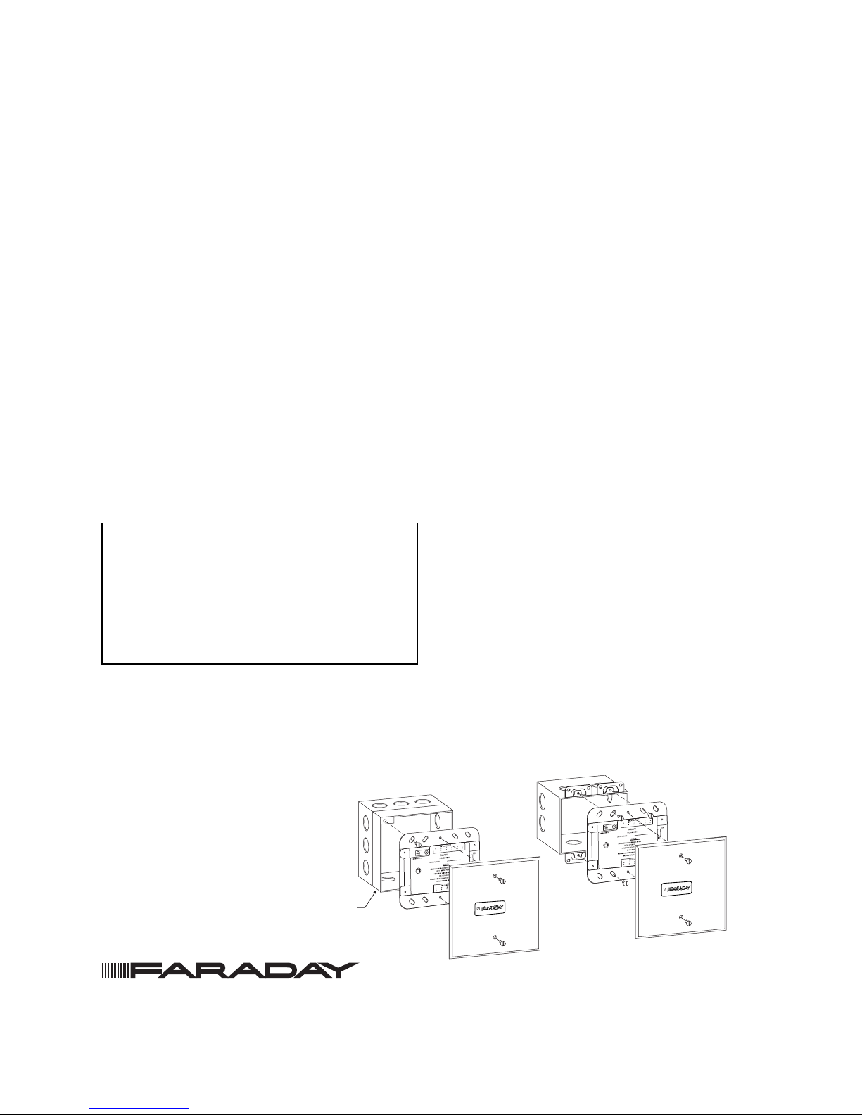
4-INCH SQUARE BOX
2 1/8-INCHES DEEP
DOUBLE GANG BOX
3 1/2-INCHES DEEP
SWITCHPLATE
5-INCHES SQUARE
(SUPPLIED)
SWITCHPLATE
5-INCHES SQUARE
(SUPPLIED)
1 1/2-INCH DEEP EXTENSION
OR
1 1/4-INCH DEEP PLASTER
RING EXTENSION
8706
8706
INSTALLATION INSTRUCTIONS AND WIRING FOR
CONTROL MODULE
P/N 8706
The 8706 Control Module interfaces polarity reversal
type of notification appliances to an Addressable
Device Circuit of a compatible Faraday Fire Alarm
Control Panel.
The 8706 supports Style Y (Class B) or Style Z (Class
A) Notification Appliance Circuit wiring. Each mod-
ule uses one address on the Addressable Device
Circuit. It does not require any mechanical address
programming. Use the 8720 Programmer/Tester to
program and test the module. Up to sixty 8706s can
connect to each Addressable Device Circuit. These
modules must be connected to the first 60 addresses
on the Addressable Device Circuit.
The power input for each 8706 comes from an
auxiliary power supply or NAC on the MPC panels
which must be power limited and UL listed for fire
protective signaling use. The 8706 maximum current
is 1.5A at 24 VDC.
PROGRAMMING INSTRUCTIONS
CAUTION:
1. To prevent damage to the device
programmer or the module, disconnect wire
from terminals 1 and 2 on TB1 of the 8706
before connecting to the 8720.
2. Only one device may be connected to the
8720 at a time.
1. Plug the programming cable of the Faraday
8720 Programmer/Tester into the two-pin
receptacle on the module. (See wiring diagram
for location.)
Figure 1
8706 Mounting
2. Set the system address for the module by
following the instructions in the 8720
Programmer/Tester Manual, P/N 315-033260FA.
3. If the 8720 has been configured for label printing,
apply the label on or near the module in a
location in which it will be clearly visible. For
information on printing labels, see the User
Instructions for the 8720 Device Programmer,
P/N 315-033260FA. The module can now be
installed and wired to the system.
MOUNTING
The 8706 must be installed in a
UL Listed electrical box.
1. Use a standard 31/2-inch deep, double gang
electrical switchbox or a 4-inch square electrical
box that is 21/8inches deep with either a 11/2-inch
deep extension or a 11/4-inch deep plaster ring
extension.
2. Connect the field wiring.
3. Insert the 8706 into the box and fasten the
device plate to the box.
4. Cover the device front plate with the 5-inch
switchplate (supplied) and fasten with two plate
screws.
WIRING
Remove all system power before installa-
tion, first battery and then AC.
(To power up, connect AC first then battery.)
Refer to Figure 2 to wire the control module for
notification appliance circuit wiring.
Siemens Industry, Inc.
Building Technologies Division • Florham Park, NJ
Tel: (973) 593-2600 • Fax: (973) 593-6670
Web: www.faradayfirealarms.com
(06-07-11)
P/N 315-034860FA-4 Page 2 of 2
Accessory Devices
Faraday Cat. No. Mfg. Part Number Description
R711-1 711-1 Polarized Auxiliary Relay
RSE 300 15073 Remote Signal Expander
Notes:
1. The accessory devices listed above may be wired to activate from the notification appliance circuits.
2. For specific wiring and installation information, read the instructions provided with each device.
Figure 2
8706 Wiring
NOTES:
1. For a list of compatible notification appliances, refer to P/N 315-096363FA.
2. Notification Appliance Circuit ratings:
Style Z, Class A or Style Y, Class B
See Installation Instructions for compatible Notification Appliances.
Supervisory current (max.): 30mA max from external supply
1mA max from addressable device circuit wiring
Alarm voltage: 24VDC nominal
Alarm current (max.): 1.5A at 24VDC nominal
NAC cable requirements:
Wire size: 18 to 14 AWG
Voltage drop (max.): 3VDC (from power supply to EOL)
3. If Earth Ground is available, the green wire should be connected to earth ground terminal (TB2, terminal 6).
4. If Earth Ground is NOT available, all the NAC wiring should be located in the same room as the module.
5. The Notification Appliance Circuit polarity is shown in active state.
6. Power Supply Input Wire Size: 18 to 14 AWG
7. The following minimum revisions are required for proper operation of the 8706.
FDLC 1.5
NAC 2.18
PANEL 5.0
DC INPUT: VDC FILTERED
FULL WAVE MODULE INPUT SUPPLY:
MPC-6000/-7000, RSE-300* (TB2) OR
UL LISTED REGULATED 24 VDC
POWER SUPPLY (POWER LIMITED).
18.8-28.2
8706 MODULE IS USED FOR
NAC SUPERVISION AND ACTIVATION
FROM ADDRESSABLE DEVICE CIRCUIT
OF A COMPATIBLE FARADAY
FIRE ALARM CONTROL PANEL OR
PREVIOUS ADDRESSABLE DEVICE
ADDRESSABLE DEVICE CIRCUIT
24VDC NOMINAL, SUPERVISED
LINE 1
LINE 2
GROUND
8706 8706
8706 MODULE IS USED FOR
NAC SUPERVISION AND ACTIVATION
SHIELD
GROUND
24K, 1/2W, 5%
END OF LINE RESISTOR
P/N 140-034677 SHIELD
STYLE Y
SUPERVISED STROBE ACTIVATION “SPECIAL APPLICATION”
SUPV: 1mA
ACTIVATED: 1.5A MAX
18.8V-28.2V FILTERED FULL WAVE RECTIFIED (SEE NOTE 2)
POLARITY SHOWN IN ACTIVE STATE
STYLE Z
24K, 1/2W, 5%
EOL RESISTOR
P/N 140-034677
ALL WIRING MUST COMPLY WITH NATIONAL AND LOCAL CODES.
DC INPUT RATED
18.8-28.2VDC FWR
SUPV: 30mA
ACTIVATED: 1.5A MAX
TB1 ON BACK SIDE
TB2 ON BACK SIDE
654321
654321
123456
123456
PROGRAMMING
POINTS
TB1 ON BACK SIDE
TB2 ON BACK SIDE
PROGRAMMING
POINTS
NOTIFICATION APPLIANCE
CIRCUIT SUPERVISED,
SEE NOTE 2
SUPERVISED
24 VDC
NAC UNITS
SEE NOTE 1
POSITIVE AND NEGATIVE
GROUND FAULT
DETECTED AT
<500 OHMS FOR
TERMINALS 3-6 ON TB1
*REFER TO RSE-300 INSTALLATION INSTRUCTIONS, P/N 315-099082FA, FOR PROPER SETTING OF SWITCH 4. THE AUXILIARY POWER OUTPUT MUST BE CONFIGURED TO “ALWAYS ON.”
When connected to NAC of MPC panel, the NAC must be configured as "Always ON."
The input power and NAC power inputs onTB2 (1-4) MUST be connected to the same source.