Farm Fans C-2120A User manual

C21A-02-2
OPERATOR’S MANUAL
C-2120A, C-2125A,
C-2130A, and C-2140A
Model Grain Dryers
1997 & LATER MODELS
Division of ffi Corporation
5900 Elmwood Ave. • Indianapolis, IN 46203
© 1998 ffi Corporation Printed in USA

READ THESE INSTRUCTIONS BEFORE
INSTALLATION and OPERATION.
SAVE FOR FUTURE REFERENCE.
Thank you for choosing a Farm Fans C-2100A
Series grain dryer. These units are among the
finest grain dryers ever built; designed to give
you excellent operating performance and reli-
able service for many years.
This manual describes the installation and oper-
ation for all standard production type C-2100A
Series dryers. These dryers are available for liq-
uid propane or natural gas fuel supply, with
either 230V or 460V three phase (60 Hz) electri-
cal power.
USE CAUTION IN THE OPERATION
OF THIS EQUIPMENT
The design and manufacture of this dryer is
directed toward operator safety. However, the
very nature of a grain dryer having a gas burner,
high voltage electrical equipment and high
speed rotating parts does present a hazard to
personnel which cannot be completely safe-
guarded against without interfering with efficient
operation and reasonable access to compo-
nents.
Use extreme caution in working around high
speed fans, gas-fired heaters, augers and auxil-
iary conveyors which may start without
warning when the dryer is operating on
automatic control.
Continued safe dependable operation of auto-
matic equipment depends, to a great degree,
upon the owner. For a safe and dependable dry-
ing system, follow the recommendations within
the manual and make it a practice to regularly
inspect the operation of the unit for any develop-
ing problems or unsafe conditions.
Take special note of the Operating Precautions
and warning listed on page 2 before attempting
to operate the dryer.
Keep the dryer clean. Do not allow fine material
to accumulate in the plenum chamber.
A CAREFUL OPERATOR IS THE BEST INSUR-
ANCE AGAINST AN ACCIDENT.
Copyright © 1998 by Farm Fans, a division of ffi Corporation. All rights reserved. No part of this publication may be used or reproduced in any form or
by any means without prior permission. Failure to comply with this notice is a violation of United States copyright laws.
WARRANTY
Farm Fans warrants its products to be free of
defects in material and workmanship. The only
obligation of the manufacturer is to repair or
replace products which have been submitted
and found to be defective within 12 months after
installation. If so found defective, the products
will be repaired or replaced without charge, this
constituting and entirely fulfilling the warranty
obligation. Farm Fans assumes no liability for
expenses incurred without written authorization;
in no event shall its liability include special or
consequential damages, or exceed the selling
price of the product.
This warranty does not cover products or parts
which have been damaged by negligent use,
misuse, alteration or accident. Some compo-
nents supplied by manufacturers are warranted
separately by those suppliers. This warranty is
exclusive and in lieu of all other warranties,
expressed or implied. Farm Fans reserves the
right to make design or specification changes at
any time, without any contingent obligation to
purchasers of products already sold.
All instructions, with the exception of those con-
cerning safety, shall be construed as recommen-
dations only; because of the many variable con-
ditions in actual installation, Farm Fans assumes
no liability for results arising from the use of such
recommendations.

1
Section 4: TEST FIRING . . . . . . . . . . . . . . . .17
Section 5: DRYER OPERATION . . . . . . . . . .21
Drying Temperatures . . . . . . . . . . . . . . . . . . . .21
Full Heat Drying . . . . . . . . . . . . . . . . . . . . . . .21
Final Moisture Content . . . . . . . . . . . . . . . . . .21
Dryer Shutdown . . . . . . . . . . . . . . . . . . . . . . .21
Operating Instructions . . . . . . . . . . . . . . . . . . .22
Startup Procedure . . . . . . . . . . . . . . . . . . . . . .23
Drying Tables . . . . . . . . . . . . . . . . . . . . . . . . .24
Section 6: DRYER ILLUSTRATIONS . . . . . . .33
Section 7: SERVICE . . . . . . . . . . . . . . . . . . .43
Seasonal Inspection and Service . . . . . . . . . .43
Propane Vaporizer Seasonal Inspection . . . . .44
Vaporizer Adjustment . . . . . . . . . . . . . . . . . . .44
Burner Control Sequence of Operation . . . . . .45
Fan Propeller Removal and Installation . . . . . .45
Fan Motor Removal and Installation . . . . . . . .47
Heater Removal and Installation . . . . . . . . . . .48
Grain and Plenum Temperature Sensor
Locations . . . . . . . . . . . . . . . . . . . . . . . . .49
SCR Drive and Meter Roll Information . . . . . .49
Meter Roll Blockage . . . . . . . . . . . . . . . . .49
To Clear Jam from Meter Roll . . . . . . . . . .50
SCR Motor Control . . . . . . . . . . . . . . . . . . . . .50
Adjusting SCR Motor Speed . . . . . . . . . . .50
Section 8: WIRING DIAGRAMS . . . . . . . . . .51
Section 9: TROUBLESHOOTING . . . . . . . . .59
General Troubleshooting . . . . . . . . . . . . . . . . .59
Improper Electronic Temperature Control
Operation . . . . . . . . . . . . . . . . . . . . . . . . .63
Improper Moisture Control Operation . . . . . . .63
OPERATING PRECAUTIONS . . . . . . . . . . . .2
Section 1: SPECIFICATIONS . . . . . . . . . . . .3
Dimensions . . . . . . . . . . . . . . . . . . . . . . . . . .3
General Specifications . . . . . . . . . . . . . . . . . .4
Auger Drive Data . . . . . . . . . . . . . . . . . . . . . .5
SCR Drive Information . . . . . . . . . . . . . . . . . .5
Section 2: TRANSPORTATION & INSTALL. .7
Transporting Dryer . . . . . . . . . . . . . . . . . . . . .7
Installation . . . . . . . . . . . . . . . . . . . . . . . . . . .7
Fuel Connection . . . . . . . . . . . . . . . . . . . . . . .8
Fuel Specs . . . . . . . . . . . . . . . . . . . . . . . . . . .9
Electrical Power Supply . . . . . . . . . . . . . . . . .9
Electrical Load, Overload Relays, and Circuit
Breakers . . . . . . . . . . . . . . . . . . . . . . . . . .10
Section 3: OPERATING CONTROLS . . . . . .11
Miscellaneous Components . . . . . . . . . . . . . .11
Control Start/Stop . . . . . . . . . . . . . . . . . . .11
Fan Switches . . . . . . . . . . . . . . . . . . . . . .11
Main/Safety Gas Shutoff Valve . . . . . . . . .11
Burner Switches . . . . . . . . . . . . . . . . . . . .11
Plenum Temperature Control . . . . . . . . . .11
Hi Lo Pressure Control . . . . . . . . . . . . . . .11
Load Auger Switch . . . . . . . . . . . . . . . . . .12
Load Timer . . . . . . . . . . . . . . . . . . . . . . .12
Unload Auger Switch . . . . . . . . . . . . . . . .12
Dryer Operator Light . . . . . . . . . . . . . . . . .12
Hour Meter . . . . . . . . . . . . . . . . . . . . . . .12
Discharge Safety Shutoff Switch . . . . . . . .12
Hinged Fast Trip Cleanout . . . . . . . . . . . .13
Meter Roll Controls . . . . . . . . . . . . . . . . . . . . .13
Meter Roll Selector Switch . . . . . . . . . . . .13
Manual Unload Control Dial . . . . . . . . . . .13
% Unload Rate (Meter Roll) Voltmeter . . .13
Vari-Trol Moisture Control . . . . . . . . . . . . .13
Meter Roll Monitor System . . . . . . . . . . . .14
Shutdown Features . . . . . . . . . . . . . . . . . . . . .15
Shutdown Indicators . . . . . . . . . . . . . . . . .15
Restarting Dryer After a Shutdown . . . . . .15
C O N T E N T S

2
Operating Precautions
Important: Keep inside of dryer clean! Do not allow chaff and other
combustible material to accumulate within air plenum chamber. Make
certain to turn off and lock out the main power before entering dryer!
1. Read and understand the operation manual
before attempting to operate the unit.
2. Keep ALL guards, safety decals, and safety
devices in place. Never operate dryer while
guards are removed.
3. Keep visitors, children, and untrained person-
nel away from dryer at all times.
4. Never attempt to operate the dryer by jump-
ing or otherwise bypassing any safety
devices on the unit.
5. Always set the main power supply disconnect
switch to OFF and lock it in the OFF position
using a padlock before performing any ser-
vice or maintenance work on the dryer or the
auxiliary conveyor equipment.
6. Before attempting to remove and reinstall the
propeller, make certain to read recommend-
ed procedure listed in Section 7 - SERVICE.
7. Keep the dryer and wet holding equipment
CLEAN. Do not allow fine material to accu-
mulate.
8. Set pressure regulator to avoid excessive
gas pressure applied to a burner during igni-
tion and when burner is in operation. See
Table 2-1 for operating gas pressures. Do
not exceed maximum recommended drying
temperatures.
9. Do not operate the dryer if any gas leak is
detected. Shut down and repair before fur-
ther operation.
10. Clean grain is safer and easier to dry. Fine
material can be highly combustible, and it
also increases resistance to air flow and
requires removal of extra moisture.
11. Use CAUTION in working around high speed
fans, gas burners, augers, and auxiliary con-
veyors which start automatically.
12. Be certain that capacities of auxiliary convey-
ors are matched to dryer auger capacities.
13. Do not operate in an area where combustible
material will be drawn into the fan.
14. The operating and safety recommendations
in this manual pertain to the common cereal
grains as indicated. When drying any other
grain or products, consult the factory for addi-
tional recommendations.
15. Routinely check for any developing gas
plumbing leaks. Check to ensure that vapor-
izer on LP models does not come into contact
with burner vanes.
Warning! Dryer Must Be Kept
Clean for Safe Operation.

3
BODY
2'-2"
STD.
C
4'-10"
E
0'-8"
8'-0"
21adims.dsf
3'-5"
3/4"
D
B
A
SUGGESTED FOUNDATION
3'-0"
6'-4"
8'-0"
0'-8" THICK
REINFORCED
CONCRETE
FOUNDATION
ELECTRICAL SERVICE
FUEL SERVICE
NOTE 1: DIMENSION ‘D’, LEG HEIGHT,
IS 16” STANDARD. OTHER HEIGHTS
ARE AVAILABLE.
Fig. 1-1 C-2100A Series dimensions
Model
C-2120A
C-2125A
C-2130A
C-2140A
‘A'
14’-0”
18’-0”
20’-0”
26’-0”
‘B'
21’-0”
25'-0"
27'-0"
33'-0"
‘C'
22’
26’
28’
34’
‘D'
16” MIN.
16” MIN.
16” MIN.
16” MIN.
Leg Pairs
Body Fan-Heater
3 1/2
3 1/2
3 1/2
4 1/2
TYPE: Continuous flow, single module with two fan-heater
units and two temperature zones provided for Dry & Cool or
Full Heat dryeration process. The upper temperature zone
and fan-heater is sized larger than the lower to optimize
Dry-Cool operation.
GRAIN COLUMNS: Two 14" galvanized steel grain
columns. Solid column dividers every two feet. Grain move-
ment through columns is controlled by the advanced elec-
tronic variable speed Vari-Trol VMD metering roll drive sys-
tem designed to precisely control grain moisture.
FANS: Two heavy-duty direct driven, quiet, vane axial fans
with full motor overload protection. All fans run at 1750
RPM, with the exception of the 3500 RPM cooling fan of the
C-2120A and C-2125A. Air Volume, HP and static pressure
are matched to grain volume.
HEATERS: Two high capacity direct-fired, efficient burners
with full electric ignition. Electronic temperature control for
precise drying heat. Starfire burners used on all lower fans
and the upper fan of the C-2120A and C-2125A; stainless
steel octagonal burners used on upper fan of C-2130A and
C-2140A models.
AUGERS: Automatically controlled top leveling augers with
power circuit for simultaneous operation of auxiliary loading
conveyor. Bottom auger unloads grain discharged from
metering rolls. Power circuits for load ing and take away
conveyors are standard. Heavy-duty construction.
AUTOMATIC CONTROL: Automatic control of all functions:
loading, drying, cooling, and discharge. Full safety control
system; automatic shutdown on wet grain outage, grain
high limit, and discharge safety shutoff. Safety circuit shut-
down indicators. Discharge shutoff feature designed to shut
down dryer and relieve grain pressure in the event the aux-
iliary grain unloading system stops or becomes plugged.
‘E'
13’-11”
15’-2”
15’-2”
15’-2”

C-2140A
1 Module with Two
Zones
26'
14"
775 Bu.
600 Bu.
35'-1-1/2"
8'-0"
12'-10"
33'-0"
8'-0"
15'-2" + 8” Fill
Hopper
39" Dia, 1750 RPM,
25 HP
28" Dia, 1750 RPM,
13 HP
7.5
3.0
8" Dia, 10 HP,
2800 BPH
8" Dia, 7.5 HP,
1760 BPH
3/4 HP, SCR
NA
154 Amps
77 Amps
455 BPH
774 BPH
780 BPH
1274 BPH
4
Basic Construction
Grain Column by Length
Grain Column Width
Holding Capacity (total)
Holding Capacity (dry and
cool)
Transport Length (hitch to dis.
auger)
Transport Width
Transport Height
Installed Length
Installed Width
Installed Height (above
foundation supports1)
Top Fan
Bottom Fan
Heaters - Max. Capacity in
Million BTU/Hr.
Top Heater
Btm. Heater (for full heat
operation)
Top Auger Size and Capacity
Bottom Auger Size and
Capacity - Maximum Rate2
Meter Roll Drive
Electric Load (fans, top & btm.
augers)3
Single Phase 230V
Three Phase 230V
Three Phase 460V
Drying Capacity - Shelled
Corn4
Dry & Cool 25-15%
Dry & Cool 20-15%
Full Heat 25-15%5
Full Heat 20-15%5
C-2120A
1 Module with Two
Zones
14'
14"
375 Bu.
320 Bu.
23'-1-1/2"
8'-0"
13'-5"
21'-0"
8'-0"
13'-9" + 8" Fill
Hopper
28" Dia, 1750 RPM,
13 HP
24" Dia, 3500 RPM,
7 HP
3.0
2.3
6" Dia, 5 HP,
1800 BPH
8" Dia, 3 HP,
945 BPH
3/4 HP, SCR
145 Amps
86 Amps
43 Amps
226 BPH
390 BPH
395 BPH
640 BPH
C-2125A
1 Module with Two
Zones
18'
14"
535 Bu.
415 Bu.
27'-1-1/2"
8'-0"
12'-10"
25'-0"
8'-0"
15'-2" + 8” Fill
Hopper
36" Dia, 1750 RPM,
15 HP
24" Dia, 3500 RPM,
10 HP
4.6
2.3
8" Dia, 5 HP,
2800 BPH
8" Dia, 3 HP,
1220 BPH
3/4 HP, SCR
186 Amps
96 Amps
51 Amps
300 BPH
505 BPH
515 BPH
835 BPH
C-2130A
1 Module with Two
Zones
20'
14"
595 Bu.
460 Bu.
29'-1-1/2"
8'-0"
12'-10"
27'-0"
8'-0"
15'-2" + 8” Fill
Hopper
39" Dia, 1750 RPM,
20 HP
28" Dia, 1750 RPM,
13 HP
6.0
3.0
8" Dia, 7.5 HP,
2800 BPH
8" Dia, 5 HP,
1350 BPH
3/4 HP, SCR
NA
132 Amps
66 Amps
350 BPH
595 BPH
600 BPH
980 BPH
1. 24" high supports required for heat reclaimer installation.
2. Actual discharge rate is controlled by meter roll speed adjustment, at 5% to 100% of maximum rate.
3. Excludes auxiliary load and unload conveyor equipment.
4. Capacities listed are wet bushels at listed input moisture content and are estimates based on drying
principles, field results, and computer simulation. Variances may occur due to physiological grain factors
(kernel size, chemical composition, variety, maturity), excessive fines, adverse weather conditions, etc.
5. Grain discharged hot from the dryer at approximately 17% output moisture should result in a final
moisture content of approximately 15% after cooling (dryeration).
TABLE 1-1 C-2100A SERIES SPECIFICATIONS

5
Top Auger
C-2120A
C-2125A
C-2130A
C-2140A
Bottom Auger
C-2120A
C-2125A
C-2130A
C-2140A
RPM
1750
1750
1750
1750
1750
1750
1750
1750
HP3
5
5
7.5
10
3
3
5
7.5
Approx.
Capacity
Bu./hr.1
1800
2800
2800
2800
9522
12202
13502
17602
Size
6"
8"
8"
8”
8"
8"
8"
8"
Drive
PD/Hub
Bore
3.6"/1-1/8"
3.6"/1-1/8"
3.6"/1-3/8"
3.6"/1-3/8"
2.8"/1-1/8"
2.8"/1-1/8"
3.6"/1-1/8"
3.2"/1-3/8"
Driven
(Teeth)
36
----
----
----
48
48
48
48
Drive
(Teeth)
25
----
----
----
15
15
15
25
Drive
Chain
#50
----
----
----
#50
#50
#50
#50
Belts
BX-112 (2)
BX-120 (2)
BX-120 (2)
BX-120 (2)
BX-93 (2)
BX-93 (2)
BX-93 (2)
BX-93 (2)
Driven
PD/Hub
Bore
10.4"/1-1/4"
18.4"/1-1/2"
18.4"/1-1/2"
18.4"/1-1/2"
13.4"/1-1/4"
10.4"/1-1/4"
12.4"/1-1/4"
13.4"/1-1/4"
1. Dryer auger capacities and power requirements vary with grain moisture content and amount of fine material in grain.
2. This Bu./Hr. listing represents the maximum meter roll discharge rate. The bottom auger capacity exceeds the maximum meter roll rate.
3. Standard output auger motors listed.
AUGERS MOTORS SPROCKETS SHEAVES
RPM
420
342
342
342
114
147
159
218
SCR Control - Part No. & Supply Voltage
DC Motor
Part number
Horsepower and set RPM
Type
Set voltage (ARM)
Full load amps (ARM)
Motor Sheave
Pitch dia.
No. and bore
Gearbox - Part no. and ratio
Gearbox Drive
Input sheave
Pitch dia.
Bore
Belt
Output Sprocket no. & bore
Chain
Meter Roll
Type and max RPM
Drive sprocket no. & bore
Setting
C-2120A
C-2125A
C-2130A
C-2140A
APPROXIMATE DISCHARGE RATES — BU/HR AT VARIOUS SETTINGS
TABLE 1-2 AUGER DRIVE DATA
TABLE 1-3 SCR DRIVE INFORMATION
C-2120A / C-2125A
415-2302-8, 230V
002-1192-0
3/4 HP, 1600 RPM
SW
155
3.9
3.0
AK32H, H-5/8"
017-1393-2, 50:1
5.7"
H-5/8
A26
H4015-1, H-1 1/8
#40 x 106"
6 Flute, 8.42 rpm
40H30, H-1
C-2130A
415-2302-8, 230V
002-1192-0
3/4 HP, 1600 RPM
SW
155
3.9
3.0
AK32H, H-5/8
017-1393-2, 50:1
5.7"
H-5/8
A26
H4015-1, H-1 1/8
#40 x 106"
6 Flute, 8.42 rpm
40H30, H-1
10%
95
122
135
176
15%
143
183
202
264
20%
190
244
270
352
25%
238
305
337
440
30%
285
366
405
528
35%
333
427
472
616
40%
381
488
540
704
45%
428
549
607
792
50%
476
610
675
880
55%
523
671
742
968
60%
571
732
810
1056
65%
618
793
877
1144
70%
666
854
945
1232
80%
761
976
1080
1408
90%
856
1098
1215
1584
100%
952
1220
1350
1760
C-2140A
415-2302-8, 230V
002-1192-0
3/4 HP, 1600 RPM
SW
155
3.9
3.0
AK32H, H-5/8
017-1403-9, 50:1
5.7"
H-7/8
A26
H40H15, H-1 1/8
#40 x 106"
6 Flute, 8.42 rpm
40H30, H-1

6

7
TRANSPORTING DRYER
An optional Transport Kit is available for transporting
the unit by truck or tractor. Make certain to observe the
following safety precautions:
1. Recommended towing hitch height: 16 to 17 inches.
2. Hitch pin to be not less than 3/4 inch in dia. and
securely fastened so it will not come out in travel.
3. Use a safety chain.
4. Dryer must be towed empty and in accordance with
applicable state or provincial regulations.
5. Recommended tire pressure 55-60 psi (cold).
6. Maximum towing speed: 45 mph
7. After first 50 miles and every 200 miles thereafter:
a. Check temperature of transport wheels' hubs and
spindles immediately after stopping. Temperature
should not exceed 150NF. May be hot to touch, but
not melting lubricant.
b. Check wheel lug bolts; they are factory torqued at 115
to 120 ft/lbs. Retighten, if required, to approximately
90 ft/lbs.
INSTALLATION
SYSTEM LAYOUT — Consider the grain handling system
and location of storage bins and existing conveyors in
selecting the dryer site, to facilitate wet grain supply
and dry grain discharge to conveyors.
SITE SELECTION — The dryer is not to be operated
inside a building or in any area not permitted by elec-
trical codes, fuel installation regulations, or insurance
requirements. Do not operate in an area where com-
bustible material can be drawn into the fans. Maintain
the required minimum distance from other structures.
Refer to Fig. 1-1 for installed dryer dimensions.
FILLING POINT — Wet grain must enter the dryer at the
hopper at the rear end of the top auger, since the top
auger moves grain forward, toward the paddle switch
controlling the top auger (except for special build front-
loading units).
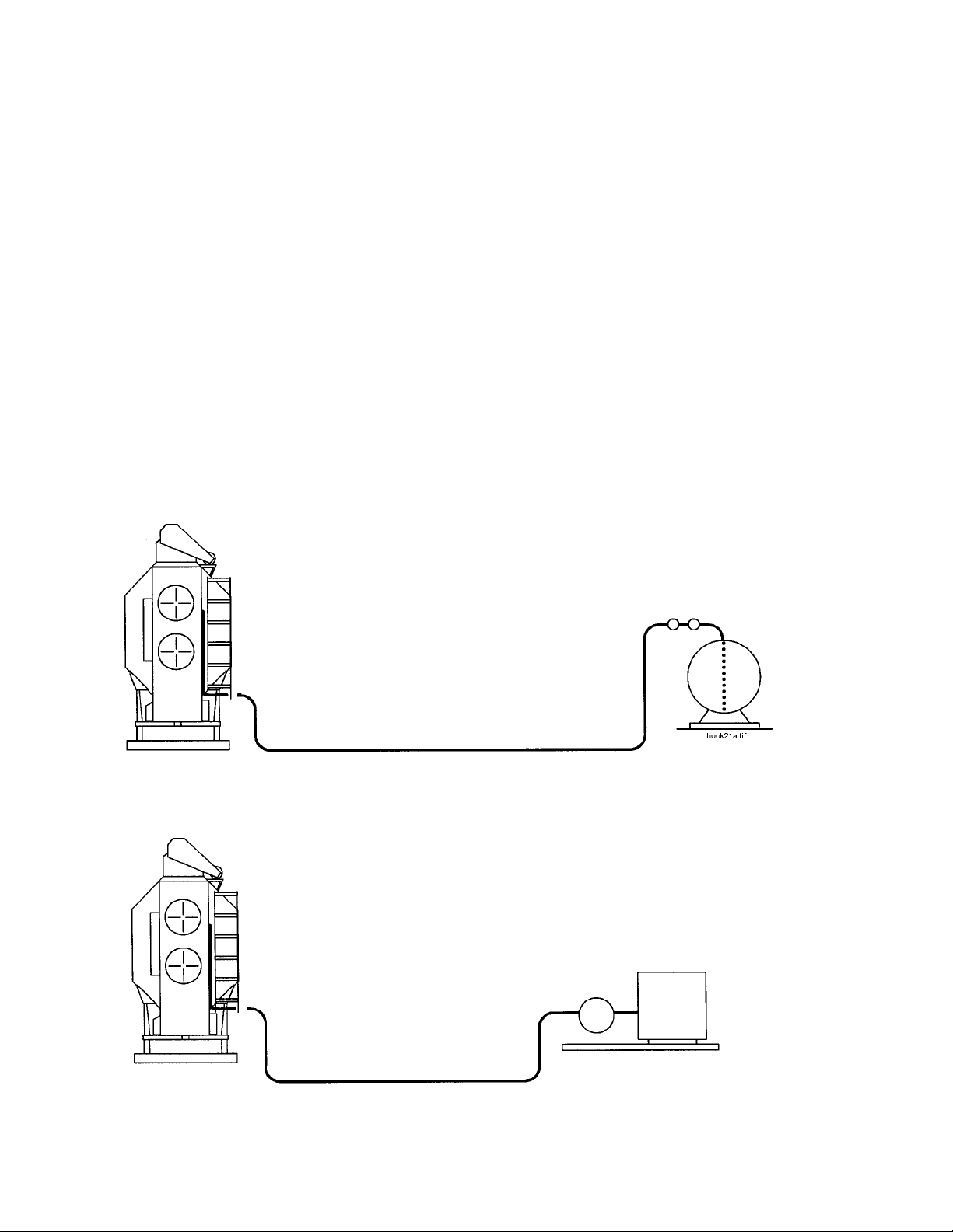
WET GRAIN SUPPLY — A wet holding bin may be utilized
to supply grain to the dryer, with gravity flow into the
dryer loading conveyor. Also, gravity flow from a
wagon or truck into a loading conveyor may be used to
fill the dryer. The top leveling auger will accept grain at
any rate up to its maximum capacity as listed in Table
1-1. In any case, the dryer must have a constant sup-
ply of wet grain. Auxiliary loading conveyors should be
sized to nearly match the capacity of the top auger, to
avoid air loss problems caused by underfilling during
high drying rate operations.
WET GRAIN LOADING — The dryer will automatically
start the top auger and any loading conveyor electri-
cally connected to the power terminal strip on the
power panel (see Section 8 - Wiring Diagrams). At the
beginning, dryer will completely fill, requiring approxi-
mately its full holding capacity. During drying, the top
auger will start and stop as required to maintain the
dryer full of wet grain.
LOAD TIMER — The unit is equipped with a top auger
Load Timer (inside ASC control box), to provide auto-
matic shutdown on wet grain outage, if the top auger
operates for a time exceeding the timer setting (field
adjustable).
DISCHARGE AUGER EXTENSIONS — Special dis-
charge auger extension kits are available, with an addi-
tional length of 1 to 10 feet (one foot increments) to pro-
vide dry grain discharge points at various distances
from the rear of the dryer, for direct discharge into ele-
vator legs or other conveyors. Extensions are avail-
able with either a solid or perforated tube.
AUXILIARY CONVEYOR OVERLOAD RELAYS —
Overload relays for the loading conveyor and take
away conveyor are factory equipped with heater ele-
ments as listed in Table 2-2 for motors on auxiliary con-
veyors. If other HP ratings are used, it is necessary to
change the heater elements to provide proper running
load protection for the motors.
DRYER FOUNDATION — The wheels are provided only
for transportation of the empty dryers to the site loca-
tion. Before assembling and installing the dryer, pre-
pare a level, secure foundation, with provisions for
dryer tie-down.
NOTE: If the dryer is to be equipped with an optional
Heat Reclaimer Package, also refer to instructions
included with the Heat Reclaimer. Heat Reclaimers for
C-2100A dryers include special dryer support struc-
tures which are intended for a conventional, flat type
concrete foundation.
DRYER PREPARATION
1. Remove Parts — Remove hopper and other parts
shipped inside dryer.
2. Wet Bin — Standard C-2120A models are equipped
with a Compact Wet-Bin. Refer to Bulletin CWB-01-2
for installation instructions. All other standard models
are equipped with a Fold-up Wet-Bin, which is installed
according to Bulletin WBF-01-2. Assemble the top
auger drive according to appropriate wet-bin installa-
tion bulletin.
3. Install Fill Hopper according to the appropriate wet-bin
installation bulletin.
4. Connect Electrical and Fuel.
5. Inspection & Testing — Thoroughly inspect dryer to
make certain all parts have been properly installed and
tightened. See FUEL CONNECTION and ELECTRI-

8
Fig. 2-1 Fuel hookup
CAL POWER SUPPLY headings in this section for
important fuel and electrical requirements. Check that
all gas fuel lines are free of leaks. Also check vaporiz-
er assembly on all liquid propane models to ensure that
vaporizer coil does not contact the burner vanes; see
Section 7 - SERVICE, for vaporizer coil inspection
details.
After dryer and all systems have been completed, start
dryer and check it for proper operation as outlined in
Section 4 - TEST FIRING.
FUEL CONNECTION
LIQUID PROPANE (LP) DRYERS WITH INTERNAL
VAPORIZERS
LIQUID DRAW — The dryer is designed to operate on
liquid propane, with liquid draw from the supply tank. A
piping system is provided on the dryer, including strain-
er, pressure relief valve, and manual shut-off valve; a
pressure regulator is provided on each fan-heater unit,
between the vaporizer and burner.
AMMONIA TANKS — Do not use propane supply
tanks which have previously contained ammonia or fer-
tilizer solutions. These substances are extremely cor-
rosive and damaging to fuel supply and burner parts.
OIL OR WATER IN TANKS — With liquid draw from
the supply tank, any water present in the tank may
freeze in the piping and controls in cold weather. To
ensure that tanks are free of moisture, the usual pre-
caution is to purge with methanol. Avoid tanks which
may contain an accumulation of oil or heavy hydrocar-
bons from long use on a vapor withdrawal system.
NATURAL GAS (NG)
GAS VOLUME AND PRESSURE — The dryer is
designed to operate on natural gas having a heat
value of about 1,000 BTU per cubic foot. The dryer is
equipped with a natural gas supply pipe system con-
nected to the heater solenoid valves. A regulated pres-
sure of 8 to 10 PSI must be provided at the connection
to the dryer, with gas available in sufficient volume to
maintain operating pressure.
LP CONNECTION
NATURAL GAS CONNECTION
CONNECTION TO LIQUID
MANIFOLD ON DRYER
Use a flexible connection
hose designed for LP gas.
See Table 2-1 for recommend-
ed line size.
Fuel supply system should conform with
National Fire Protection Association stan-
dards.
Consult propane supplier for proper fittings,
connection hose, and safety controls
required to meet standards.
Do not use a pressure regulator at the sup-
ply tank.
Open LP shut-off valves slowly to prevent
accidental closing of excess flow valves.
PROPANE SUPPLY TANK
Recommended minimum of 1,000
gallons connected for liquid draw.
CONNECTION TO NATURAL
GAS MANIFOLD ON DRYER
See Table 2-1 for recommend-
ed line sizes.
NATURAL GAS METER and REGULATOR
See Table 2-1 for required pressure and typical
maximum fuel flow rates.

ELECTRICAL POWER SUPPLY
POWER SUPPLY — An adequate power supply and
proper wiring are important factors for maximum per-
formance and long life of the dryer. Electrical service
must be of adequate size to prevent low voltage dam-
age to motors and control circuits. All dryers should be
field provided with a dependable equipment ground.
Electrical power supply should conform to local, state,
or provincial requirements.
POWER SUPPLY DISCONNECT — All dryers should
be equipped with a power disconnect switch external to
the ASC Control Box to permit total power shutdown
before opening ASC dead front, as required for inspec-
tion and service. The power disconnect switch should
be located close to the dryer for quick shutdown.
TRANSFORMERS WIRING VOLTAGE DROP —
Contact the service representative of the power suppli-
er to advise of the additional load to be placed on the
line. Check on KVA rating of transformers, considering
total horsepower load. The power supply wiring, main
switch equipment, and transformers must be capable
of providing adequate motor starting and operating
voltage. Voltage drop during motor starting should not
exceed 14% of normal voltage, and running voltage
(after motor is at full speed) should be within 8% of nor-
mal voltage.
ELECTRICAL LOAD — Table 2-2 indicates the electri-
cal load in horsepower and full load current, for motors
on the dryer, and for auxiliary loading and take-away
conveyors which can be directly connected to the
power circuits in the dryer control panel.
OVERLOAD RELAYS — Most overload relays are
adjustable from 85% to 115% of normal load in
amperes by an adjustment knob in each relay (see
Overload Relay Heater specs in Table 2-2). Dryers are
shipped with overload relay heater elements installed
for the auxilliary conveyor motor sizes as listed in Table
2-2. If different motors are used, the heater elements
must be changed to provide adequate motor overload
protection.
CONNECTING AUXILIARY CONVEYORS
The maximum sizes of auxiliary conveyor motors which
can be powered directly from the dryer's power termi-
nals are listed in Table 2-2. See appropriate power cir-
cuit wiring diagram for terminal connection numbers.
To connect auxiliary auger motors which are LARGER
than the maximum, refer to the following informa tion.
A. Motors that must be powered from a source outside the
dryer must use a separate contactor and overload pro-
tection device for each motor.
B. For automatic operation with 230V 3-phase dryers: use
230V contactor coils and connect LOADING coil to
POWER TERMINALS 7 and 9. Connect UNLOADING
coil to POWER TERMINALS 13 and 15.
C. For automatic operation with 460V 3-phase dryers:
either use a control stepdown transformer to power
230V contactor coil, or use 460V contactor coils and
connect them as described in item B above.
D. When conveyor motors are powered from an external
source and they are connected for automatic opera-
9
Liquid
Propane
(LP)
Natural
Gas
(N)
Total Max Fuel Flow1 -
Gallons/Hour
Recommended Liquid Line Size
Heater Orifice Drill Size (Pre-
1994 models in parentheses)
Operating Pressure Range (PSI)
Heater Pressure Gauge (Pre-
1994 models in parentheses)
Total Max Fuel Flow1- Thousand
Cubic Ft./Hr.
Minimum Pressure at Connection
to Dryer, PSI
Recommended Minimum Line
Size - 100' Distance
Heater Orifice Drill Size (Pre-
1994 models in parentheses)
Operating Pressure Range (PSI)
Heater Pressure Gauge
C-2120A
Top Btm.
3.0 2.3
57
1/2"
.250" .218"
3-15
3.0 2.3
8
2"
.375" .312"
2-7
1. Maximum fuel flow rates listed assume full heat output for gas line sizing purposes. In normal operation the flow rates would
be considerably lower than indicated, due to actual setting used and cycling of heater.
Maximum Heat Capacity (Million BTU/hr)
TABLE 2-1 FUEL SYSTEM RECOMMENDATIONS
C-2125A
Top Btm.
4.6 2.3
75
1/2"
.281" .218"
5-22
4.6 2.3
8
2"
.438" .312"
3-8
C-2130A
Top 2Btm.
6.0 3.0
98
1/2"
.438" .250"
(.344")
3-8 5-22
(5-22)
6.0 3.0
8
2"
.563" .375"
(.500")
3-8
C-2140A
Top 2Btm.
7.5 3.0
114
1/2"
.500" .250"
3-8 5-22
7.5 3.0
8
2.5"
.625" .375"
3-8

10
tion, their overload protective switches should be con-
nected in series and then connected into the dryer
safety circuit. For recommended connections, refer to
motor overload protection connections shown in the
SAFETY CIRCUIT portion of the control circuit wiring
diagram in Section 8.
Voltage
1r230V
3r230V
3r460V
1r230V
3r230V
3r460V
1r230V
3r230V
3r460V
1r230V
3r230V
3r460V
1r230V
3r230V
3r460V
Top
Auger
5
5
5
22
13
6.5
C22.8
C16.3
C8.67
80
60
30
Btm.
Auger
3
3
3
16
8.6
4.3
C15.1
C11.3
C5.92
80
60
30
TABLE 2-2 ELECTRICAL LOAD, OVERLOAD
RELAYS, and CIRCUIT BREAKERS
C-2120A
Top
Fan
10/13
10/13
10/13
58
36
18
F65.5
C36.6
C21.4
100
90
50
Btm.
Fan
7.5/9
7.5/9
7.5/9
42
28
14
F43.0
C30.3
C16.3
80
60
30
Aux.
Conv.1
7.5 (two)
7.5 (two)
7.5 (two)
34
20
10
C30.3
C22.8
C13.7
-- 2
-- 2
-- 2
145
86
43
Voltage
3r230V
3r460V
3r230V
3r460V
3r230V
3r460V
3r230V
3r460V
3r230V
3r460V
Top
Auger
7.5
7.5
20
10
C22.8
C13.7
90
50
Btm.
Auger
5
5
13
6.5
C16.3
C8.67
90
50
C-2130A
Top
Fan
20
20
56
28
E77
C33.0
100
50
Btm.
Fan
13
13
36
18
C36.6
C21.4
60
50
Aux.
Conv.1
10 (two)
10 (two)
26
13
C30.3
C16.3
-- 2
-- 2
132
66
Horsepower
Full Load
Amps
Max Running
Load (dryer
only, amps)
Circuit
Breaker
Rating -
amps
Overload
Heater
Element
Voltage
3r230V
3r460V
3r230V
3r460V
3r230V
3r460V
3r230V
3r460V
3r230V
3r460V
Top
Auger
10
10
26
13
C30.3
C16.3
90
50
Btm.
Auger
7.5
7.5
20
10
C22.8
C13.7
90
50
C-2140A
Top
Fan
25
30
66
33
E78
E72
100
63
Btm.
Fan
13
13
34
17
C36.6
C21.4
60
50
Aux.
Conv.1
10 (two)
10 (two)
26
13
C30.3
C16.3
-- 2
-- 2
154
77
Horsepower
Full Load
Amps
Max Running
Load (dryer
only, amps)
Circuit
Breaker
Rating -
amps
Overload
Heater
Element
Voltage
1r230V
3r230V
3r460V
1r230V
3r230V
3r460V
1r230V
3r230V
3r460V
1r230V
3r230V
3r460V
1r230V
3r230V
3r460V
Top
Auger
5
5
5
22
13
6.5
C22.8
C16.3
C8.67
80
60
30
Btm.
Auger
3
3
3
16
8.6
4.3
C15.1
C11.3
C5.92
80
60
30
C-2125A
Top
Fan
10/16
10/16
10/16
83
41
20.5
F84.8
C44
C25
100
90
50
Btm.
Fan
10
10
10
58
25
12.5
F65.8
C33.0
C18.0
80
60
30
Aux.
Conv.1
7.5 (two)
7.5 (two)
7.5 (two)
34
20
10
C30.3
C22.8
C13.7
-- 2
-- 2
-- 2
186
96
51
Horsepower
Full Load
Amps
Max Running
Load (dryer
only, amps)
Circuit
Breaker
Rating -
amps
Overload
Heater
Element
Horsepower
Full Load
Amps
Max Running
Load (dryer
only, amps)
Circuit
Breaker
Rating -
amps
Overload
Heater
Element
NOTES:
1. The motor current and maximum dryer running loads listed
above are based on auxiliary conveyor motor sizes shown.
The maximum size motor that can be powered directly through
the dryer’s ASC control is listed in the Aux. Motor Data chart.
All larger than maximum auxiliary conveyor motors require
separate contactors and overload protectors with coil circuits
connected to the dryer for automatic operation.
IMPORTANT: All standard Model C-2100A dryers are factory
equipped with overload relay heater elements sized for auxil-
iary motors listed in charts above. If the actual auxiliary motors
used are of a different size, the elements must be changed.
2. Auxiliary motors are controlled by the top and bottom auger cir-
cuit breakers.
Size
3/4 HP DC
SCR MOTOR DATA
Control Amps / Volts
7.5A / 230VAC
Motor Amps / Volts
4.8A / 155VDC
Model
C-2120A
C-2125A
C-2130A
C-2140A
AUXILIARY MOTOR DATA
Std. Aux. Motor
7.5 HP
7.5 HP
10 HP
10 HP
Max. Aux. Motor
10 HP (3r230V)
10 HP (3r230V)
15 HP (3r230V)
15 HP (3r230V)

MISCELLANEOUS COMPONENTS
CONTROL STOP/START
The Main Control circuit is energized by pushing the
green START button. The green light on the START
button indicates the control circuit is ON and that all the
safety switches are reset.
Push the red STOP button to stop the dryer control cir-
cuit.
FAN SWITCHES
The group of FAN switches controls the UPPER and
LOWER fan motors. The green START button will light
when the fan motor contactor has been energized.
MAIN/SAFETY GAS SHUT-OFF VALVE
VALVE OPERATION — This valve is an electrically
energized, manual reset type valve. The valve's elec-
tric solenoid is energized only when the dryer CON-
TROL CIRCUIT is turned ON. See Figs. 6-1 for valve
location.
The valve has a "free handle" lever that cannot allow
gas flow to the dryer until the dryer control circuit is
energized. Only then does the lever engage to allow
the handle to be manually raised to the latched posi-
tion, thereby opening the valve. The gas flow will stop
when the valve's solenoid is de-energized (see CAU-
TION below).
CAUTION: Do not use the operating handle to close
the valve. Always de-energize the electrical hold-
ing circuit while the valve is fully open for positive
closing action.
An "open" and "shut" indicator is provided on the side
of the Main/Safety Shut-off valve. (An orange indicat-
ing bar aligns itself with the words "open" or "shut.")
See Fig. 6-2.
BURNER SWITCHES
The group of BURNER switches controls the UPPER
and LOWER burners. Each burner switch has a red
light to indicate a LOCKOUT condition.
Each burner is ignited by turning the appropriate burn-
er switch ON. Ignition should take place after a short
purge time.
NOTE: In order to light the burner, the Main/Safety Gas
Shut-off Valve's handle must be manually reset to
OPEN and the appropriate fan must be ON.
Both burner switches should be ON for FULL HEAT
drying. The lower burner switch should be OFF for
DRY/COOL drying. Turn the burner selector switch
OFF to stop each burner.
A dryer shutdown will occur and the appropriate burner
LOCKOUT light will be energized if the burner fails to
ignite or the burner flame is not sensed for a period of
approximately 60 seconds. Several minutes may be
required to allow the lockout to automatically reset itself
before ignition may again be attempted.
PLENUM TEMPERATURE CONTROLS
PLENUM CONTROLLER OPERATION — Drying tem-
peratures are controlled by the Electronic Temperature
(ET) plenum controllers located on the ASC control
panel. Each fan-heater is controlled by a separate con-
troller (see Fig. 6-7).
The controller senses air plenum temperature and
cycles burner from Hi-Fire to Lo-Fire operation to main-
tain desired drying temperature as indicated by plenum
temperature indicator on the asc panel.
CHECKING AND ADJUSTING PLENUM TEMPERA-
TURE — To determine drying temperature within the
air plenum chamber(s), depress the appropriate
CHECK SWITCH (labeled "HOLD TO READ") and
observe temperature indicated on the meter. To reset
the plenum drying temperature, simply rotate the prop-
er adjustment knob to the desired temperature setting.
The ET system will automatically cycle the burner to
maintain the set temperature (see Fig. 6-7).
HI/LO FIRE PRESSURE CONTROLS
HI-FIRE / LO-FIRE — When a heater is operating on
Hi-Fire, its burner is supplied with a relatively large flow
of gas from both the Hi-Fire gas solenoid valve and the
Flow Control valve. When a heater is operat ing on Lo-
Fire, only the Flow Control valve supplies gas flow to its
burner.
PROPANE HI-FIRE — On propane models, the Hi-Fire
gas pressure for the burner is controlled by the Gas
Pressure Regulator. For maximum heat capacity, the
regulator should be adjusted WHILE OPERAT ING ON
HI-FIRE to provide maximum burner pressure, as
shown by the pressure gauge on the unit. For maxi-
mum pressure, see Table 2-1 - Fuel System
Specifications (maximum listing for LP "Operating
Pressure Range").
NATURAL GAS HI-FIRE — For natural gas models,
the Hi-Fire gas pressure is controlled by adjusting the
large Manual Shut-off valve within the line which sup-
plies the fan-heater. For maximum heat, set the shut-
off valve to provide approx. 8 PSI of pressure WHILE
BURNER IS OPERATING ON HI-FIRE. For maximum
pressure, see Table 2-1 - Fuel System Specifications
(maximum listing for Natural Gas "Operating Pressure
Range").
LO-FIRE — The Lo-Fire gas pressure is controlled by
the Flow Control valve (see Fig. 6-4).
PROPANE LO-FIRE — On propane models, set the
Lo-Fire gas pressure to the lowest setting listed in the
LP "Operating Pressure Range" in Table 2-1, by rotat-
ing the knob on the Flow Control valve. Lock setting
with an Allen wrench after making this adjustment.
11

12
Burner must be operating on Lo-Fire when making this
adjustment.
NATURAL GAS LO-FIRE — For natural gas models,
turn the Flow Control valve handle to provide the low-
est pressure listed for (N) "Operating Pressure Range"
in Table 2-1, while the burner is operating on Lo-Fire
(see Fig. 6-4).
BURNER CYCLE — When burner is operating proper-
ly, it should automatically cycle at regular intervals from
Hi-Fire to Lo-Fire, as indicated by the corresponding
pressure change on the gas pressure gauge. It is not
necessary for burner to cycle with short 5 to 10 second
intervals, BUT IT IS IMPORTANT THAT THE BURNER
DOES CYCLE OCCASIONALLY.
If burner remains in Hi-Fire and does not cycle,
increase Gas Regulator pressure setting on propane
models, or the Manual Shut-off valve pressure on nat-
ural gas models (see Fig. 6-5), in order to satisfy the
thermostat setting. Do not exceed the maximum oper-
ating pressure range listed in Table 2-1.
If burner remains in Lo-Fire and does not cycle,
decrease Lo-Fire gas pressure slightly by readjusting
the Flow Control valve. Do not decrease the valve set-
ting to the extent where a noticeable burner flutter or
popping noise can be heard, as caused by flame back-
fire into the burner cup.
LOAD AUGER SWITCH (Top Auger)
The LOAD AUGER switch has three positions: ON,
OFF, and AUTO.
The ON position is recommended when initially filling
an empty dryer. With switch ON, the top auger will
operate, but the Load Timer will be de-energized.
With the switch in either AUTO or ON, the top auger
automatically starts and stops, as required, to keep the
dryer full of grain.
The AUTO switch position is the normal setting and is
used to automatically stop the dryer when the wet grain
supply is exhausted. With switch in the AUTO position,
the Load Timer will be energized whenever the load
auger is operating. If the load auger and timer operate
continuously for a period longer than the timer setting,
the timer will automatically shut down the dryer.
LOAD (Top Auger) TIMER
FUNCTION — The top auger loads the wet bin inter-
mittently, depending on when the paddle switch calls
for more grain. The Load Timer checks that the load
auger doesn't run beyond the normal time to fill the wet
grain holding bin. If, due to inadequate wet grain sup-
ply, the load auger runs longer than a normal refill time,
the Load Timer causes a dryer shutdown.
The Load Timer, located within the ASC control box, is
an automatic reset type timer. The amber LOW GRAIN
shutdown indicator will light whenever a shutdown is
caused by the Load Timer.
TIMER SETTING — To set the Load Timer, observe
the normal time required to fill the wet bin, then rotate
the front dial to set timer to the average refill time plus
several additional minutes.
NOTE: The Load Timer can be set to several time
ranges of operation. The timer is factory set in the 60-
minute range mode. With this arrangement, the no. 1
mark on the dial face equals 1/6 of the 60-minute
range or 10 minutes.
UNLOAD AUGER SWITCH
The UNLOAD AUGER switch has two positions: OFF
or AUTO.
With switch in the AUTO position, the auger runs con-
tinuously and the meter rolls are controlled by the
Meter Roll Selector Switch position (manual/off/auto).
With switch in the OFF position, the meter rolls and
auger are stopped.
The UNLOAD AUGER switch will energize the meter
roll safety circuit monitor. This monitor will cause a
dryer shutdown if meter roll rotation is not sensed for a
period longer than (3) minutes and the METER ROLL
shutdown indicator will be energized.
DRYER OPERATOR LIGHT
LIGHT OPERATION — The dryer
operator light is designed to act as
either a dryer monitor signal light, or a
night convenience light.
SWITCH POSITIONS — The three-position switch pro-
vides ON, OFF, or MONITOR operation. When the
switch is set ON, the light will stay energized even
when the dryer is shut down. When the switch is set to
MONITOR, the light will be ON only when the dryer is
operating.
NOTE: The 115V light circuit is intended for 100 watt
bulb operation. Do not install an oversize light bulb!
HOUR METER
The hour meter, located on the ASC Control Panel, is
useful in keeping track of seasonal use of the dryer and
determining when service is required. The hour meter
is non-resetting and accumulates hours only when the
upper fan is powered.
DISCHARGE SAFETY SHUTOFF SWITCH (DSS)
The DSS functions as an electrical safety shutoff switch
and a grain release hatch. Located on the discharge
tube assembly (see Fig. 3-1), this feature is designed
to automatically shut down the dryer and relieve grain
LIGHT
OFF
ON
MONITOR
Fig. 3-1 Discharge assembly

pressure, in the event the auxiliary grain unloading sys-
tem stops or becomes plugged. After grain overflow is
removed from the discharge tube and the grain release
hatch falls to its normal position, the device will auto-
matically reset and allow the dryer to be restarted.
The discharge assembly is equipped with a Collect-A-
Sample tube to allow a safe and easy method of
obtaining a grain sample. To operate, simply rotate the
tube; 180° rotation provides maximum discharge.
HINGED FAST-TRIP CLEANOUT
The dryer is factory equipped with a "fast-trip" cleanout
mechanism beneath the unload auger, as shown in Fig.
3-2. The individual fast-trip doors allow easy cleanout
of accumulated materials.
METER ROLL CONTROLS
METER ROLL SELECTOR SWITCH
Switch has three positions: MANUAL, OFF, and AUTO.
The UNLOAD AUGER switch must be ON in order to
operate meter rolls. With switch in the MANUAL posi-
tion, the meter roll speed is controlled by the MANUAL
CONTROL dial on the ASC panel (see Fig. 6-7).
With switch in the AUTO position, meter rolls are con-
trolled automatically by the Moisture Controller.
With the Meter Roll Selector set to Manual, the
Moisture Controller can only display grain temperature,
but cannot control anything. With Meter Roll Selector
set to OFF, the Moisture Controller display is also off.
MANUAL UNLOAD CONTROL DIAL
The Manual Control dial sets meter roll
speed to a constant unload rate. Set the
desired % unload rate by watching the %
Unload Rate volt meter as the Manual
Control dial is adjusted. See Dryer Tables
in Section 5 for suggested start-up settings.
% UNLOAD RATE (METER ROLL) VOLT METER
The % UNLOAD RATE volt meter monitors the DC
ARMATURE VOLTAGE on the SCR MOTOR driving
the meter rolls. This voltage represents the %
UNLOAD RATE of the dryer and should range from 7%
to 100% as the unload speed is changed. Be sure to
use the % Unload Rate volt meter as the primary indi-
cator of the % unload rate, as the Manual Control Dial
setting will be close to but not as accurate as the volt
meter reading.
VARI-TROL MOISTURE CONTROL
The Vari-Trol Moisture Control works on the principle
that grain moisture and grain temperature are closely
related. Monitoring grain temperature, combined with
manual testing of the grain's final moisture content, will
allow the operator to determine the proper tempera-
ture/moisture relationship. Using the digital-display
temperature control assembly on the ASC panel, the
operator can view the current grain temperature and
set the desired grain temperature (setpoint), in the
manner described as follows.
13
lever in locked position
lever in open position
closure door "closed"
TRIPCLEN.DSF
closure door "open"
(would normally hang vertically)
To "fast dump" grain, swing
levers downward. To close,
swing door closed and pull
lever upward into locked
position.
Fig. 3-2 Fast-trip cleanout assembly
Grain
Temp
Indicator
Set Point
Indicator
Display Reset
Arrow
Buttons
Honeywell
ALM
OUT
PV
DISP RESETFUNCT SETUP
Function Setup
Fig. 3-3 Vari-Trol moisture controller
SERVICE TIP: Open cleanout doors at end of season and remove debris.
Doors may be left open during the off season for better drainage.

14
NOTE: As previously stated, with the Meter Roll
Selector set to Manual, the Moisture Controller can
only display grain temperature, but cannot control
meter roll speed. With Meter Roll Selector set to OFF,
the Moisture Controller display is also off.
SETTING TEMP
a. Push the DISP (display) button once and current set-
point will be displayed as indicated by the letters SP
(setpoint) in the lower left-hand corner.
b. Raise or lower Setpoint to desired temperature by
pushing the triangle buttons to increase or decrease.
c. Push RESET to return to measured temperature. SP
will not be displayed. If display is inactive for 60 sec-
onds, it will automatically return to measured tempera-
ture display. If moisture control is turned off while in the
SP mode, the newly entered setpoint will be canceled.
Operating with Automatic Moisture Control
1. See Drying Time Tables in Section 5 for initial drying
time, and Dryer Operation Charts also in Section 5 for
initial % Unload Rate. Then start the dryer on manual
control.
2. Measure discharged grain moisture. If adjustments are
required, change the Manual Control Dial as required;
allow dryer to operate for one grain pass before
rechecking moisture.
Note: Time (min.) = Holding Capacity (Bu.) x 60
for one grain pass Unload Rate (Bu/Hr)
3. After the grain discharge has been readjusted and sta-
bilized at desired moisture content, note the tempera-
ture on the Moisture Controller and adjust the setpoint
to the temp noted. Be sure to push Reset button after
entering a new setpoint before proceeding.
4. Move the Unloading Switch from MAN to OFF, then to
AUTO, pausing 5 to 6 seconds in the OFF position.
This pause is necessary for the Moisture Control to
reinitialize. If the Moisture Control has been correctly
reinitialized, first zero degrees and then the correct
grain temperature will display after the switch is set to
AUTO. Failure to wait for a complete reset can cause
a lengthy delay in the time the Moisture Control needs
to arrive at the correct meter roll speed. Also important:
Do not change the manual unload rate dial while in the
auto mode.
5. The Moisture Controller will begin automatically con-
trolling the meter roll speed to compensate for changes
in the grain input moisture by maintaining the setpoint
temperature entered.
6. If large changes in grain input moisture are encoun-
tered, repeat the setup procedure to establish a new
setpoint temperature.
7. When restarting a loaded dryer following a shutdown
period, the dryer should be operated in the MANUAL
mode, until the newly dried grain has passed the RTD
grain sensor (2/3 of the grain pass time) and the grain
temperature has stabilized, before switching to the
AUTOMATIC mode. The Moisture Control setpoint
should not require readjustment.
METER ROLL MONITOR SYSTEM
Operation — The meter roll monitor system is designed
to provide automatic shutdown of the dryer if the meter
rolls fail to rotate due to obstructions, malfunction, or
forgetting to turn the meter roll selector switch ON. The
monitor system will function only when the unload
auger circuit is energized, as required for normal meter
roll operation.
The main monitor system components are briefly
described as follows:
Proximity — The Meter Roll Proximity switch is mount-
ed on the meter roll drive end of the dryer, on the side
opposite the SCR drive motor. This switch senses the
rotation of the meter rolls and sends an electrical signal
to the meter roll monitor in the ASC control box. (See
Fig. 3-4 and General Control Circuit in Section 8.) The
light on the switch indicates LOAD ON each time a
rotation has been sensed.
The proper switch adjustment is 1/4” clearance
between Proximity switch head and the rotating target.
The Proximity switch is slotted to allow readjustment, if
required. When properly adjusted, the LOAD ON indi-
cator will light every time the target rotates near the
proximity switch. (For service information, see Bulletin
MRM-02-2.)
NOTE: Earlier meter roll monitor switches used a set
screw and two hex nuts as a rotating target. The sug-
gested gap for this type switch is 3/4" between the
bearing collar and proximity switch sensing head.
Meter Roll Monitor — The meter roll rotation is moni-
tored by the solid state Meter Roll Monitor Relay in the
ASC control box. The monitor is active whenever the
Unload Auger switch is in the AUTO position. If the
Monitor fails to see a change (either opening or clos-
ing) in the Proximity Switch signal within three minutes,
the safety circuit will be broken and the dryer will auto-
matically shut down. The Monitor resets automatically
when the control start button is pushed.
PROXIMITY SWITCH
056-1865-7
1/4" GAP
SIDE
VIEW
ROTATING
TARGET
MRALT.DSF
Fig. 3-4 Meter roll monitor

SHUTDOWN FEATURES
SHUTDOWN INDICATOR LIGHTS
The Shutdown Indicator Lights are connected within
the 115V safety control circuit to identify the causes of
unexpected dryer shutdown problems. These lights
are located on the ASC control panel and are identified
in Fig. 3-5.
NOTES:
• NO indicator light will come ON if a motor overload
relay trips open.
• The shutdown detector unit is designed so that if a
malfunction occurs within the unit, such as a bad light
or poor wiring connections, it will not prevent the dryer
from operating, but will only cause abnormal action of
the indicator lights.
RESTARTING DRYER AFTER A SHUTDOWN
1. Investigate the cause of shutdown and perform any
necessary adjustments or corrections. For addi tional
information, refer to "Control Circuit Not Energized"
heading within Section 9, TROUBLE SHOOTING. As a
future reference, it may be advisable to make a record
of the cause, as indicated by the shutdown indicator.
NOTE: On rare occasions, several dryer safety
devices may act to interrupt the safety control circuit
simultaneously. If this occurs, the LOWEST NUMBER
INDICATOR LIGHT on the detector will always take pri-
ority, as the unit is constructed to indicate only one
cause at a time.
2. Press the dryer START button. When the start button
is pressed, the dryer control light should come ON,
indicating that all safety devices have been reset and
the dryer is operational.
Following is a list of shutdown indicators. For the most
common shutdown causes, see Section 9,
Troubleshooting.
15
SHUTDOWN INDICATOR LIGHTS - ASC PANEL
• LOW GRAIN (auto resets immediately)
• METER ROLL MONITOR (auto resets immediately)
• GRAIN HI-LIMIT (auto resets after cooling)
• BURNER HI-LIMIT (auto resets after cooling)
• PLENUM HI-LIMIT, upper & lower (auto resets after
cooling)
UNMONITORED SAFETY SHUTDOWN DEVICES
• Unload auger overload relay
• Load auger overload relay
• Upper fan overload relay
• Lower fan overload relay
• SCR overload relay
• Discharge shut-off switch
• Auxiliary load overload relay
Fig. 3-5 Shutdown indicator lights (For connection details and additional information, see Section
9 - Troubleshooting, and the safety circuit portion of the control circuit in Section 8.)

16

Before the dryer is filled with grain and placed into
actual drying operation, thoroughly inspect the unit
and check out the operation as described in the follow-
ing steps.
1. Set controls and switches as follows:
CONTROL TEST FIRING SETTING
Burner Switch OFF
Load Auger switch OFF
Unload Auger Switch OFF
Unloading Switch OFF
Manual Unload Setting Adjust to minimum
Loading Timer 30 minutes
2. Inspect metering rolls and inside of dryer.
Open all metering roll access doors and all hinged fast-
trip clean-out doors and carefully inspect each com-
partment for any bolts, nuts or other foreign hardware
which may have dropped into these areas during dryer
installation and setup. Remove all material present to
prevent possible jamming of the meter rolls or bottom
auger and contamination of dried grain.
Check the inside of air plenum chambers and remove
all foreign materials.
3. Check plumbing for leaks.
Open the main fuel supply valve to allow fuel flow to the
electrically operated Main/Safety Gas Shut-off Valve.
Note: Open the supply valve slowly to prevent acci-
dental closing of the excess-flow valve within supply
system.
Proceed only after all fuel leaks have been corrected.
4. Turn on all circuit breakers located in the PSC power
box.
5. Start dryer control circuit.
Push the control START button. The green light on the
control START button should immediately light, indicat-
ing the safety circuit and control circuit are energized to
allow dryer operation.
6. Check conveyor motors rotation.
A. With the wet grain supply shut off, quickly bump
(jog) the Load Auger Switch to the ON position. The
top auger should rotate clockwise as viewed from the
drive end. Any wet grain auxiliary sup ply conveyors
connected to the dryer power terminals should also
start and rotate in the proper direction.
B. Quickly bump (jog) the Unload Auger Switch to the
ON position. The lower auger should rotate counter-
clockwise as viewed from drive end. Any dry grain aux-
iliary conveyors connected to the dryer power terminals
should also start and rotate in the proper direction.
C. With the Unload Auger Switch ON, set the Meter
Roll Selector Switch to MANUAL position and check
the direction of rotation. The RH metering roll shaft
should rotate clockwise as viewed from rear end of the
dryer. See Fig. 6-14.
7. Check meter roll operation.
With Unloading Auger still operating, rotate the MANU-
AL UNLOADING control to increase meter roll speed
and check the metering roll drive mechanism for prop-
er operation throughout its full speed range. The
UNLOAD RATE should range from approximately 7%
to 100%. Make sure all drive belts and chains are
properly tensioned and that all sections of the meter
rolls rotate properly and smoothly.
8. Check fan motor rotation.
Bump (jog) each fan switch and observe direction of
motor rotation. All fans should turn COUNTER-
CLOCKWISE, as seen when looking into the fan inlet.
NOTE: On three-phase model dryers, if all dryer
motors run backward, they can easily be reversed by
changing the dryer's power supply connection.
Auxiliary conveyors which have been field connected
may have to be reversed individually.
9. Check burner safety lock-out function.
Start the Upper Fan and turn the Upper Burner switch
to the ON position. With the Main/Safety Shutoff valve
kept in the normally closed position for this portion of
the test, the burner control system's PL Safety Circuit
should cause a dryer shutdown after a short interval.
The red Upper Burner LOCKOUT light should indicate
the shutdown.
Turn the Upper Burner OFF, Restart the Control Circuit,
and repeat the test procedure for the Lower Burner.
10. Open the Main/Safety Gas Shut-off valve by using the
handle.
With the control circuit activated (green light ON), man-
ually operate the lever on the Main/Safety Gas Shut-off
valve to turn the fuel ON. Inspect all fuel lines and con-
nections for possible leaks. ANY GAS LEAKS MUST
BE CORRECTED.
11. Starting fan and firing burner.
Individually start Upper and Lower Fans. Observe the
number of seconds for each fan motor to reach FULL
RPM. With proper voltage supply and wire sizing to
dryer, the fan should reach full speed within 7 seconds
and the motor running current should be within accept-
17

18
able limits to the full load amperage listed in the
Electrical Specification Charts.
If fans start properly, turn the Upper and Lower Burner
switches to ON position. The burners should fire after
a short purge interval and gas pressure should be indi-
cated on the pressure gauge for each burner.
Adjust Upper and Lower Plenum Temperature
Controllers on the ASC panel to approximately 200°F
to cause both burners to operate on Hi-Fire. Observe
gas pressure indicated on each pressure gauge, then
turn plenum controllers down to their minimum setting
to cause burners to cycle into Lo-Fire. As the burner
controllers are turned down, each gas pressure gauge
should show a noticeable drop in pressure, indicating
the Hi-Fire gas solenoid valve has closed and the burn-
er is being supplied with only the reduced flow of gas
through the flow control valve and the Lo-Fire solenoid
valve.
NOTE: For additional information concerning the actu-
al recommended gas pressure settings and the adjust-
ment procedure, refer to Section 3 - OPERATING
CONTROLS.
The final gas pressure adjustments MUST be made
after dryer is filled with grain.
12. Check moisture control operation.
A. Set all switches to the positions shown in chart in
step 1.
B. Start the dryer control circuit, turn the Unload
Auger Switch to ON, and set the Meter Roll Selector
Switch to the MANUAL position. Adjust the UNLOAD-
ING RATE to 30%.
C. The Moisture Controller should be reading approx-
imately the same as ambient temperature unless there
is still residual heat in the dryer from previous burner
operation. Set the Moisture Controller to match the
measured temperature displayed. See Section 3 -
OPERATING CONTROLS for setting controller.
D. Set the Meter Roll Selector switch to AUTO, paus-
ing for a few seconds in the off position. The unloading
rate should begin at the previously adjusted manual
unloading rate.
E. Increase the Moisture Controller set point approx-
imately 30°F above the current measured temperature.
The Unloading Rate should drop to approximately 2/3
the manual unload rate, or 20%. Additional tempera-
ture increase will not cause further unload rate reduc-
tion.
F. Decrease the Moisture Controller set point approx-
imately 95°F below the measured temperature. The
unloading rate will increase to approximately twice the
manual unloading rate, or 60%.
G. Set the Meter Roll Selector Switch to MANUAL
position and reset the unload rate to 60%. Set the
Moisture Control back to match the displayed mea-
sured temperature. Again switch the Meter Roll
Selector Switch to AUTO, pausing in the OFF position.
Verify that the control starts at the manual unload rate.
Note that by decreasing the moisture control set point
temperature 95°F the unload rate will not exceed
100%.
13. Check safety shutdown devices.
A. Meter roll monitor
Start dryer control circuit and turn Unload Auger Switch
to ON, position Meter Roll Selector Switch to MANUAL,
and set Unload Rate to minimum setting. Allow unload
to operate for approximately (5) minutes. No shut down
should occur.
Set Unload Rate to 100% for at least 15 seconds then
position the Meter Roll Selector Switch to OFF. In
approximately (3) minutes, the dryer should shut down
and the meter roll monitor shutdown indicator will be lit.
B. Low grain monitor and fill switch
Adjust the Load Timer to a short time period of approx-
imately five minutes or less. Start the dryer control cir-
cuit and set the Load Auger Switch to ON. The Load
Timer should not be powered and no shut down should
occur after a five-minute or longer filling time.
If the physical setup of the grain drying system permits
safe access to the fill switch (also known as the paddle
switch), located on the wet bin, perform the following
test:
CAUTION: Use care to avoid falling and
causing personal injury.
While the load auger is running, slowly rotate the fill
switch box counterclockwise by hand until the load
auger stops. The load auger should stop when the
switch box is rotated to a position 50-55° from hori zon-
tal. Slowly rotate the box clockwise and the dryer
should restart at 15-20° before horizontal. Readjust fill
switch if required. See Fig. 4-1 for switch position dia-
gram.
Position the Load Auger Switch to AUTO. The Load
Timer should begin counting down and the dryer
should shut down after five minutes of loading. The
LOW GRAIN indicator light should be energized on the
control panel. Be sure to reset the Load Timer to the
appropriate time.
C. Discharge shut-off switch
Remove the shipping screw securing the hinged cover
on the discharge box if required. Check to see that the
cover works freely and seats tightly against the dis-
charge box approx. 1/4" from proximity switch.
Start the control circuit, turn the Unload Auger Switch to
ON, and Meter Roll Selector Switch to MANUAL. Lift
the cover on the discharge auger approximately one
inch. The dryer should immediately shut down; how-
ever, no monitor indicator will be energized.
14. Stop dryer operation.
This manual suits for next models
3
Table of contents