FARM SCAN Jackal v2 User manual


AM-Jackal-2 more quick guides @ www.farmscanag.com/jackal July 2013
1
General Description
TABLE OF CONTENTS
General Description __________________________ 1
Technical Specifications _____________________ 1
Disclaimer________________________________ 1
Installation _________________________________ 2
Parts List_________________________________ 2
Parts Pictorial _____________________________ 2
Mounting & Installation_____________________ 2
Connections ________________________________ 3
Available connections ______________________ 3
Power Connection _________________________ 4
Overview __________________________________ 5
Button Functions __________________________ 5
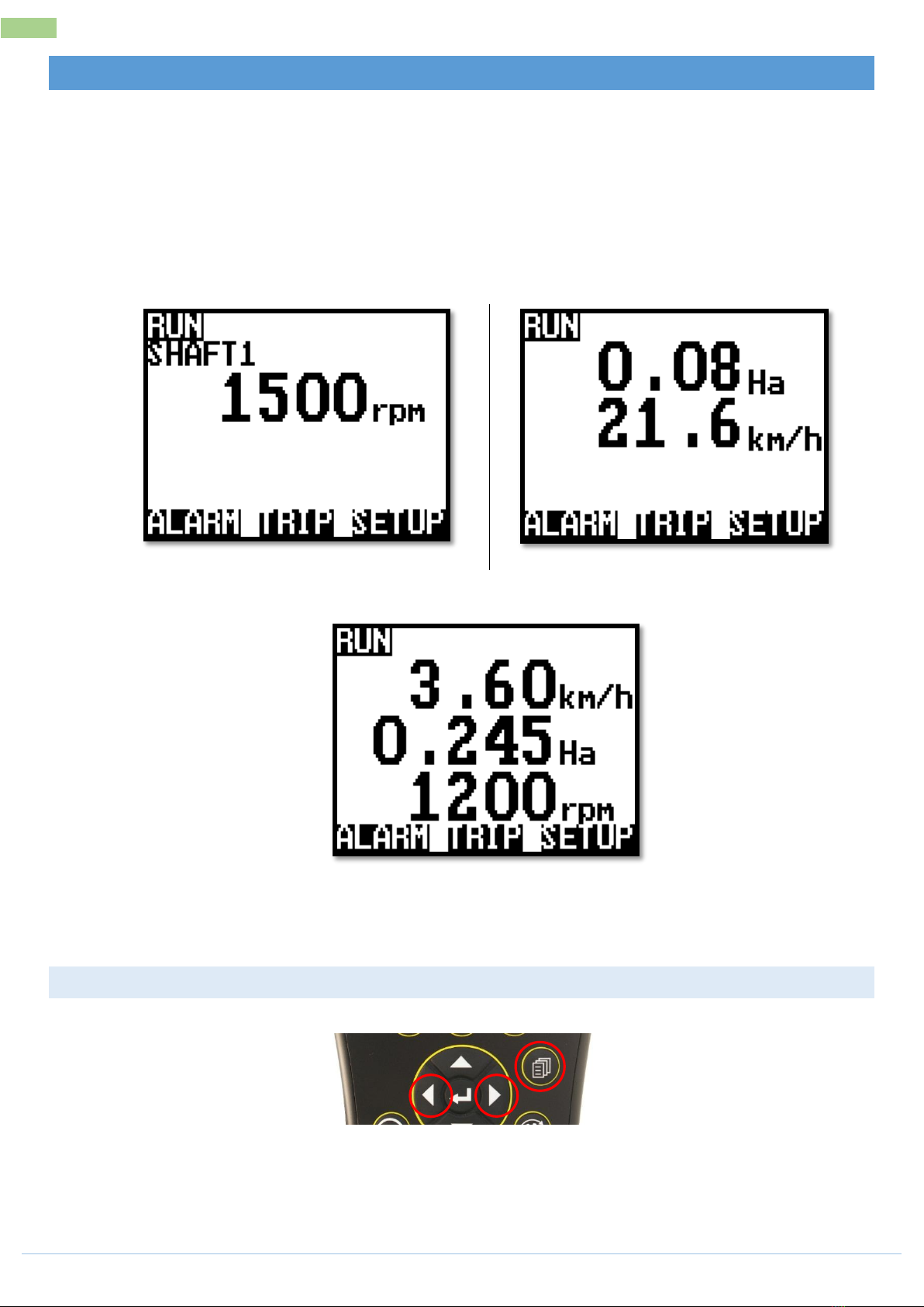
Screen Layout_______________________________ 6
More information on screen _________________ 6
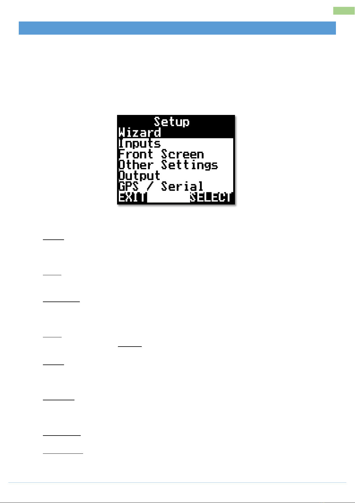
Main Menu (Setup Overview) __________________ 7
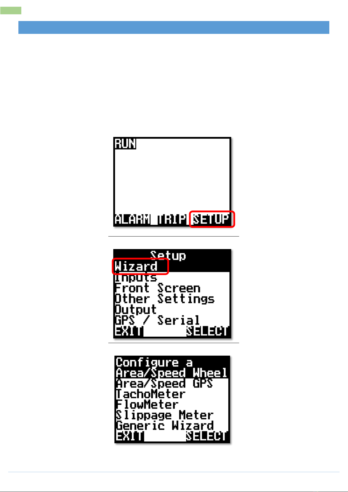
Using the Wizard ____________________________ 8
Area & Speed Meter Setup (Wizard) _____________ 9
Description_______________________________ 9
Sensors Required __________________________ 9
Available Connections (Refer Page 3) __________ 9
Setup ___________________________________ 9
Calibration _______________________________ 9
Option 1 : Target Method _________________ 9
Option 2 : Manual Ratio___________________ 9
Calibration (Continued) ____________________ 10
Area & Speed GPS (Wizard) ___________________ 11
Description______________________________ 11
Sensors Required _________________________ 11
Available Connections (Refer Page 3) _________ 11
Setup __________________________________ 11
Tacho/RPM Meter Setup (Wizard)______________ 12
Description______________________________ 12
Sensors Required _________________________ 12
Available Connections (Refer Page 3)__________12
Setup___________________________________12
Flow Meter (Wizard)_________________________ 13
Description ______________________________13
Sensors Required _________________________13
Available Connections (Refer Page 3)__________13
Setup___________________________________13
Calibration ______________________________13
Option 1 : Target Method (auto cal with a known
volume)_______________________________ 13
Option 2 : Manual Ratio (Enter a known PPL/PPG
factor) ________________________________13
Calibration (Continued) ____________________14
Slippage Meter (Wizard)______________________ 15
Description ______________________________15
Sensors Required _________________________15
Available Connections (Refer Page 3)__________15
Setup___________________________________15
Calibration ______________________________15
User Defined Setup (Manual) __________________ 16
Description ______________________________16
Inputs ____________________________________ 17
Front Screen _____________________________18
Front Screen –Order ______________________19
Other Settings______________________________ 20
Output____________________________________ 21
GPS/Serial _______________________________22
Trips (Explained) ____________________________ 23
Description ______________________________23
Setup___________________________________23
Alarm ____________________________________ 24
Description ______________________________24

AM-Jackal-2 more quick guides @ www.farmscanag.com/jackal July 2013
1
General Description
GENERAL DESCRIPTION
The Jackal is capable of monitoring multiple functions simultaneously –e.g. In a 4 bin / tank Airseeder
application a single Jackal can monitor and display several shafts, bin levels, air pressure and more.
There are a total of 14 inputs available which are combined with a single output for emergency shutdown,
batching functions and speed proportional pulse outputs.
The inputs can have both high and low alarm thresholds set which can trigger emergency shutdown systems.
The unit employs a large daylight readable LCD to provide legible characters on the display and enable
calibration data to be clear and descriptive.
Up to 14 values can be displayed or used as totals, with up to 24 recordable trips allowing the operator to
track numerous jobs in a period of work. The Jackal can be put ‘on hold’ by the operator or by a suitable
signal from the machinery, so that periods of machine operation that should not accumulate as a work total
can be excluded from trip totals.
Our onboard calibration wizard makes setup a breeze! It’s simplified with the ability to enter either a factor
(pulses per unit) or simply drive/run a set amount whilst the unit is counting the pulses and let the system
calculate its own factor.
Each input can be used to display information using imperial and metric units.
TECHNICAL SPECIFICATIONS
Power
Requirements
9 –16
VDC
@
250mA
Display
128 x 64 Mono Graphic LCD
Operating
T
emperatur
e
0 to
50C
Storage T
emperatur
e
-5 to
65C
Dimensions
135mm
x
100mm
x
30mm
(HxWxD)
Sensor Inputs
13
Input 1
Up to 1000 pulses per
second.
Inputs 2 –
6
Up to 400 pulses per
second.
Inputs 7 –
8
Analog Voltage
0 –
5V
Inputs 9 –
13
On/Off:
0V or
12V
Outputs
1
Output 1
Low side drive 3A
maximum load.
DISCLAIMER
The warranty offered on this Farmscan AG product is limited to the repair or replacement of the faulty
goods. No liability will be accepted for loss of profit or productivity. WARRANTY IS VOID if power is not
connected as described on PAGE 6.

July 2013 more quick guides @ www.farmscanag.com/jackal AM-Jackal-2
2
Installation
INSTALLATION
PARTS LIST
REF
PART NUMBER
DESCRIPTION
QTY
1
A-Jackal
Jackal Monitor
1
2
AH-407
Mounting Bracket
1
3
P-321
11 Way Input Plug
Green & Grey set
1each
colour
4
AC-105
5m Power Cable
1
5
HM-506
Screw Driver
1
AM-200
Warranty Card
1
AM-Jackal
Manual
1
PARTS PICTORIAL
MOUNTING & INSTALLATION
The Jackal is
provided
with a
suction window mount.
Slide
mount
onto unit and push
sideways
to lock into place. Make sure you hear a c
lick
of the
mount
locking
into
place.
Place in a
convenient position
on the
windscreen
and using the
toggle
lever
pictur
ed,
push all the
way to the
bottom
until lever locks into
position.
Note:
Monitor should
be
mounted
in a clearly visible
position
in the cab for the
operator, but
not in
a
position where
it is
subject
to
intense
heat or
moistur
e.
1
2
3
4
5

AM-Jackal-2 more quick guides @ www.farmscanag.com/jackal July 2013
3
Connections
CONNECTIONS
The connector on the rear of the Jackal has the following connection points available for use.
AVAILABLE CONNECTIONS
A1
GND
(Ground/Earth/0V)
B1
IN1
(1x Coil Input ONLY /Prox/Reed sensor)
A2
IN13
(Prox/Reed/Switch/Alarm)
B2
IN2
(Prox/Reed/Switch/Alarm)
A3
IN12
(Prox/Reed/Switch/Alarm)
B3
IN3
(Prox/Reed/Switch/Alarm)
A4
IN11
(Prox/Reed/Switch/Alarm)
B4
IN4
(Prox/Reed/Switch/Alarm)
A5
IN10
(Prox/Reed/Switch/Alarm)
B5
IN5
(Prox/Reed/Switch/Alarm)
A6
IN9
(Prox/Reed/Switch/Alarm)
B6
IN6
(Prox/Reed/Switch/Alarm)
A7
IN8
(Varying
volt
sensor)
B7
IN7
(Varying
volt
sensor)
A8
Not Used
B8
Out1
(Solenoid/Shutoff/Pulse/Radar output
) –Pulls to GND
^
A9
Not Used
B9
Out2
(
+12V Supply O
ut) –Sensor Power ^^
A10
RS232
Tx (Transmit)
B10
BATT +VE (+12V Battery
T
erminal)
A11
RS232
Rx (Receive)
B11
BATT -VE
(0V/GND
Battery
Ter
minal,
Vehicle
Gr
ound)
^ B8/OUT1 is Open Circuit when the output is NOT ACTIVE, and is connected to GND when the
output is active
^^ B9/OUT2 will only power the sensors when the unit is turned on
Any Inputs 1-13 can be used as remote/run hold

July 2013 more quick guides @ www.farmscanag.com/jackal AM-Jackal-2
4
Connections
POWER CONNECTION
Power connection must come direct from the battery terminals. WARRANTY IS VOID if power is not
connected as described in this section.
1. Connect power cable supplied DIRECTLY TO BATTERY
2. Ring terminals are used for battery connection and the end with Ferrules attached is used to connect
to the rear Jackal. (Refer page 3 for connection instructions)
3. Connect Ground to BATT -VE, Terminal B11 using the RED with BLACK stripe wire
4. Connect +12 Volts (+battery terminal) to BATT +VE, Terminal B10 using the red wire
5. Ensure that the battery connection to the Jackal is +12 Volts
Connecting 24V to the Jackal will VOID WARRANTY
Disconnect the terminal plugs from
the Jackal if ARC WELDING on
machinery

AM-Jackal-2 more quick guides @ www.farmscanag.com/jackal July 2013
5
Overview
OVERVIEW
BUTTON FUNCTIONS
1. Power On/Off Key
a. Power is
turned
on by a short press of the ON/OFF Key (1
second).
b. Power is
turned
off by
two (2)
short
pr
esses.
2. Run/Hold Key
a. The RUN/HOLD key has a dual function.
b. Press RUN/HOLD once to place the ‘MONITOR ON HOLD’.
c. Press RUN/HOLD again to resume operation.
d. The RUN/HOLD state is indicated in the top left hand corner of the screen. When the monitor is in
RUN mode, the unit displays RUN to signify that the monitor is active.
e. When the monitor is in HOLD mode the unit displays HOLD
3. Menu/Page Key
a. The MENU/PAGE key is used for setting up the ports as well as returning to the main screen from
TRIPS or TOTAL displays
4. Select Key (3 of)
a. The Jackal has 3 soft keys placed directly under the LCD. These keys will change function in different
menus.
b. The function of the soft key is indicated at the bottom of the screen directly above the button.
5. Navigation Keys (Up, Down, Left, Right, Enter)
a. The Round navigation (NAV) keys are used to navigate UP/DOWN & LEFT/RIGHT in calibration screens.
b. ENTER is used to activate the selection
4
3
1
2
5

July 2013 more quick guides @ www.farmscanag.com/jackal AM-Jackal-2
6
Screen Layout
SCREEN LAYOUT
The main operation screens show live information and alarms, measured using the sensors attached to the
Jackal.
The Jackal can display one (1), two (2) or three (3) pieces of live information at a time. If more than three
pieces of information are available, the MENU/PAGE or LEFT/RIGHT can be used to cycle through the
available information, as described below.
1 line of information (1 UP)
Example: Line 1 –RPM
2 lines of information (2 UP)
Example: Line 1 –Ha | Line 2 –km/hr
3 line of Information (3 UP)
Example: Line 1 –km/hr. | Line 2 –Ha | Line –3 RPM
MORE INFORMATION ON SCREEN
When more than 3 lines of information are selected use:
MENU/PAGE or LEFT/RIGHT to cycle through the available information.

AM-Jackal-2 more quick guides @ www.farmscanag.com/jackal July 2013
7
Main Menu (Setup Overview)
MAIN MENU (SETUP OVERVIEW)
Below is a generic overview of the main menu.
The manual will guide you through two (2) setup scenarios.
a. Wizard Setup
b. Manual Setup
FRONT SCREEN > SETUP
Wizard Allows the user to run a predefined wizard for setting up common task
Area/Speed Wheel, Area/Speed GPS, TachoMeter, FlowMeter, Slippage Meter & Generic
Wizard for fast setup.
Inputs Allows the user to select the ports in which sensors are connected to.
A choice of 13 inputs are available
Front Screen Allows the user to enable/define/move/edit up to 13 line items on the front screen
You can also name the input port, select the number of decimal places displayed & edit the
alarms
Other Allows the user to set in implement width (m), External run/hold options & alarm
notification Settings options
Output Allows the user to select output options from the Jackal.
Output as a frequency / pulse (radar), external audible/visual alarm, batch/trip function,
other external function if required.
GPS/Serial When an external gps is connected the user can view & ensure the gps is setup correctly.
Setup baud rate & confirm gps messages (NMEA messages RMC or GGA+VTG are required)
Latitude, Longitude, heading, speed, date & time
About Jackal Shows current version of Jackal software installed on the unit
Factory Reset Returns the Jackal to factory default. All settings & options cleared

July 2013 more quick guides @ www.farmscanag.com/jackal AM-Jackal-2
8
Using the Wizard
USING THE WIZARD
FRONT SCREEN > SETUP > WIZARD
The Jackal has an inbuilt wizard function for common tasks.
Current Wizards include easy setup for:
a. Area/Speed Wheel –Wheel pickup & sensor required
b. Area/Speed GPS –No Wheel Senor required GPS only
c. TachoMeter (RPM)
d. FlowMeter (Direct readout or batch)
e. Slippage Meter (GPS v Wheel Input)
f. Generic Wizard (You can choose the input, screen position & calibration factors)

AM-Jackal-2 more quick guides @ www.farmscanag.com/jackal July 2013
9
Area & Speed Meter Setup (Wizard)
AREA & SPEED METER SETUP (WIZARD)
DESCRIPTION
The Jackal can display Speed & Area in any combination of km/mph or ha/acre.
A pickup can be mounted either on a wheel hub or shaft.
SENSORS REQUIRED
Wheel sensor pickup 2 or 3 wire
Magnet (Used with 2 wire sensor)
AVAILABLE CONNECTIONS (REFER PAGE 3)
This setup section assumes that physical wiring for the required sensors have been completed. If not please
refer to page 3 on wiring requirements
SETUP
FRONT SCREEN>SETUP>WIZARD>AREA/SPEED WHEEL
1. Using the NAV KEYS select the current port the wheel sensor input is connected to & press NEXT
2. Press EDIT (to enable the port)
3. Using the EDIT KEY select your unit of pulse for calibration
M (Meter) | ft. (Feet) | yd.(Yard) | in (Inch) | km (Kilometer) | mi (Miles)
CALIBRATION
Ensure that the sensor & pickup are end-end before continuing with either method
Mark bottom centre of tyre on which the sensor is fitted and peg ground in corresponding position
CHOOSE CALIBRATION METHOD OF TARGET OR MANUAL RATIO AS DESCRIBED BELOW:
OPTION 1 : TARGET METHOD
1. Measure out a known distance to calibrate i.e. 20m to use the auto calibrate function.
oPeg the 2 corresponding points.
2. Enter the target distance by pressing the EDIT key i.e. 20
3. Press EXIT when done
4. Press the START button and move slowly forward to allow pulses to register.
5. When you arrive at the centre mark point of tyre to peg press STOP
6. Press CALC
OPTION 2 : MANUAL RATIO
1. Enter a known wheel factor (i.e. Wheel circumference)
2. Scroll down to the Manual Ratio (1.000000) and press the EDIT Enter the known wheel factor
3. Press EXIT when done
4. Select NEXT
5. Enter your implement Width EDIT in desired UOM (M,FT,YD,IN,KM,MI)
This will show covered area on the main screen
6. Scroll down to enable/disable the External/Run hold (Refer page 3 for inputs)
7. If the External/Run Hold is enable select the input port to where it is connected

July 2013 more quick guides @ www.farmscanag.com/jackal AM-Jackal-2
10
Area & Speed Meter Setup (Wizard)
CALIBRATION (CONTINUED)
4. Scroll down to Alarm Beep and EDIT the number of audible beeps to be heard on the selected port if
an alarm sounds.
5. Select NEXT
6. Choose your units of display
Ha (Hectares) | Ac (Acres) | m^2 (Meters squared) | Km^2 (Kilometers squared)
7. Select NEXT
8. You can now EDIT the audible alarm points for a Min & Max range to be notified of a problem
9. Select NEXT
10. Create a name for your port if desired by pressing EDIT
11. Use the UP/DOWN/LEFT/RIGHT to change the letters. (Max 3 letters)
12. Select EXIT when done
13. Select NEXT
14. Confirm that you wish to display km/hr. or mph on the next line (YES or NO)
15. Select NEXT
16. Return to the front screen to confirm setup is complete by selecting EXIT
** Refer to page XX to edit decimal places, rename the port or change the unit of measure i.e. to
mph,acres,m,ft
Example: Speed (km/h) & area meter
Example: Speed (mph) & acre meter
Example : Setup to measure distance

AM-Jackal-2 more quick guides @ www.farmscanag.com/jackal July 2013
11
Area & Speed GPS (Wizard)
AREA & SPEED GPS (WIZARD)
DESCRIPTION
The Jackal can display Speed & Area in any combination of km/mph or ha/acre. A
GPS can be used in place of a wheel or shaft pickup.
SENSORS REQUIRED
GPS : Programmed with RMC or GGA+VTG NMEA messages.
Baud Rate : 4800,9600,19200,38400,115200
AVAILABLE CONNECTIONS (REFER PAGE 3)
This setup section assumes that physical wiring for the required sensors have been completed. If not please
refer to page 3 on wiring requirements.
SETUP
FRONT SCREEN>SETUP>WIZARD>AREA/SPEED GPS
1. Using the EDIT KEY select the baud rate of the attached GPS (4800,9600,19200,38400,115200)
2. When the correct baud rate has been selected the NMEA messages will change from N (No) to Y
(YES)
3. Press NEXT
4. Enter your implement Width EDIT in desired unit of measure (m,ft,yd,in,km,mi) –This will show
covered area on the main screen
5. Scroll down to enable/disable the External/Run hold (Refer page 3 for inputs)
a. Disabled | Normally off | Normally on
6. If the External/Run Hold is enable select the input port to where it is connected
7. Scroll down to Alarm Beep and EDIT the number of audible beeps to be heard on the selected port if
an alarm sounds.
8. Select NEXT
9. Choose your units of display
a. Ha (Hectares) | Ac (Acres) | m^2 (Meters squared) | Km^2 (Kilometers squared)
10. Select NEXT
11. You can now EDIT the audible alarm points for a Min & Max range to be notified of a problem
12. Select NEXT
13. Create a name for your port if desired by pressing EDIT
14. Use the UP/DOWN/LEFT/RIGHT to change the letters. (Max 3 letters)
15. Select EXIT when done
16. Select NEXT
17. Confirm that you wish to display km/hr or mi/hr on
the next line (YES or NO)
a. If NO is selected the Jackal will only display
Ha or Acre
18. Select NEXT
Return to the front screen to confirm setup is complete by
selecting EXIT

July 2013 more quick guides @ www.farmscanag.com/jackal AM-Jackal-2
12
Tacho/RPM Meter Setup (Wizard)
TACHO/RPM METER SETUP (WIZARD)
DESCRIPTION
The Jackal can display a RPM (Revolutions per minute) Useful for
monitoring fans or shafts.
SENSORS REQUIRED
Sensor pickup 2 or 3 wire
Magnet for use with 2 wire or bolt head if using a proximity
AVAILABLE CONNECTIONS (REFER PAGE 3)
This setup section assumes that physical wiring for the required sensors have been completed. If not please
refer to page 3 on wiring requirements.
SETUP
FRONT SCREEN>SETUP>WIZARD>TACHOMETER
1. Using the NAV KEYS select the current port the sensor input is connected to & press NEXT
2. Press EDIT (to enable the port)
3. Using the EDIT KEY select pulse/rev (Pulse/Revolution)
4. Using the NAV KEYS scroll to MANUAL RATIO 1.000000 & press EDIT
5. Enter the number of magnets or pickup location per revolution.
a. I.e. If 2 magnets are installed change 1 to 2
6. Press EXIT when done
7. Press NEXT
8. Select 1: rpm
9. You can now EDIT the audible alarm points for a Min & Max range to be notified of a problem
10. Select NEXT
11. Create a name for your port if desired by pressing EDIT
12. Use the UP/DOWN/LEFT/RIGHT to change the letters. (Max 3 letters when in 3 up mode)
13. Select EXIT when done
14. Select NEXT
15. Select EXIT to return to the front screen to confirm setup
** Refer to page XX (Front Screen) to edit decimal places or to rename the port
Example: 1UP monitoring 1 shaft
Example: 2UP monitoring 2 shafts

AM-Jackal-2 more quick guides @ www.farmscanag.com/jackal July 2013
13
Flow Meter (Wizard)
FLOW METER (WIZARD)
DESCRIPTION
The Jackal can be configured to monitor application rates of solid or
liquid products. If only one input is used the main screen will display the
flow information is L/min or Gal/min, or, if using the speed & area
function the Jackal can also display L/ha or Gal/Acre. At no stage can the
Jackal take into account multiple sections turning on an off and
adjusting the Ha/Ac to suit.
SENSORS REQUIRED
Flow Sensor ( 2 or 3 wire)
AVAILABLE CONNECTIONS (REFER PAGE 3)
This setup section assumes that physical wiring for the required sensors have been completed. If not please
refer to page 3 on wiring requirements.
SETUP
FRONT SCREEN>SETUP>WIZARD>FLOWMETER
1. Using the NAV KEYS select the current port the flow sensor input is connected to & press NEXT
2. Press EDIT (to enable the port)
3. Using the EDIT KEY select your unit of pulse for calibration
L (Litres) | GAL (gallons US)
CALIBRATION
OPTION 1 : TARGET METHOD (AUTO CAL WITH A KNOWN VOL UME)
1. Scroll down to TARGET and press EDIT
2. Enter a known volume to calibrate the flow meter against. I.e. 20L or
5Gal.
3. Press EXIT
4. Start the pump, press START open the valve and pulses will now
accumulate.
5. As SOON as the volume has been emptied press STOP
6. Press CALC, this will now enter the PPL/PPG factor into the Manual
Ratio
OPTION 2 : MANUAL RATIO (ENTER A KNOWN PPL/PPG FACTOR)
1. Scroll down to Manual Ratio
2. Press EDIT
3. Enter the known PPL/PPG factor as labelled on the flow meter
4. Press EXIT
5. Press NEXT

July 2013 more quick guides @ www.farmscanag.com/jackal AM-Jackal-2
14
Flow Meter (Wizard)
CALIBRATION (CONTINUED)
17. Choose your units of display : L/Min or Gal/Min Press NEXT
18. You can now EDIT audible alarm points for a Min & Max range to be notified of a problem
19. Press NEXT
20. Create a name for your port if desired by pressing EDIT
21. Use the UP/DOWN/LEFT/RIGHT to change the letters. (Max 5 letters)
22. Select EXIT when done
23. Select NEXT
24. Select NEXT
25. Return to the front screen to confirm setup is complete by selecting EXIT
Example : 1 UP monitoring a flow meter in L/min
Example : 1 UP monitoring a flow meter in gal/min
Example : 3 UP monitoring a flow in L/Min & Speed/Area with a wheel sensor connected

AM-Jackal-2 more quick guides @ www.farmscanag.com/jackal July 2013
15
Slippage Meter (Wizard)
SLIPPAGE METER (WIZARD)
DESCRIPTION
The Jackal has been designed to provide the operator with the ability to
compare and two inputs and provide the result as a percentage. This is
applicable in industries such as agriculture when speed over ground in not
necessarily equivalent to rotational speed of the wheel/s. This wizard will
enable you to set up a comparison between wheel speed and actual speed
(using GPS)
SENSORS REQUIRED
Wheel or gearbox sensor input
GPS
AVAILABLE CONNECTIONS (REFER PAGE 3)
This setup section assumes that physical wiring for the required sensors have
been completed. If not please refer to page 3 on wiring requirements
SETUP
FRONT SCREEN>SETUP>WIZARD>SLIPPAGE METER
1. Using the NAV KEYS select the current port the wheel sensor input is connect to & press NEXT
2. Using the EDIT key, select the baud rate of the GPS that is connected.
a. GPS messages will be displayed on the Jackal monitor when the correct baud rate is chosen.
3. Press NEXT
CALIBRATION
1. Drive at a constant speed above 3km/hr.
2. Wheel input will then increment up (displayed in Hz) & GPS speed will start to show.
3. As the system self-calibrates the slip % will get closer to 0%.
4. When the slip has settled close to 0%press NEXT
5. EDIT the necessary alarm points to be notified of any alerts & select NEXT
6. The port by default is called “SLIP” & no need to be renamed. Press NEXT
7. You will now be prompted to “Configure next display to km/hr?” This will display slip % on the 1st of
the Jackal & km/hr on the 2nd line. Select YES or NO
8. Wizard Configuration Successful , Select NEXT
9. Select EXIT to return to the main screen.
Example : 2 UP monitoring slippage versus ground speed displayed as a percentage
VS

July 2013 more quick guides @ www.farmscanag.com/jackal AM-Jackal-2
16
User Defined Setup (Manual)
USER DEFINED SETUP (MANUAL)
DESCRIPTION
At any stage you can manually setup the Jackal to your requirements without using the wizard.
Manual setup of the Jackal requires setup in multiple areas. Navigate from the front screen via SETUP
FRONT SCREEN > SETUP
INPUTS
Select & enable the Input that sensors are connected into the rear of the Jackal
CALIBRATE
Calibrate each input following the TARGET or MANUAL RATIO method
FRONT SCREEN
Define the order of lines, label, Unit of measure (UOM), decimal places & alarm points that you wish
to be displayed on the front screen. NB: You can display multiple UOM on the front screen using only
one input. E.g. View Ha & Ac at the same time.
OTHER SETTINGS
Use this to define implement width for Ha/Ac accumulation, External Run/Hold port if being used &
number of alarm notifications
OUTPUT
Use this only to setup the Jackal to output a pulse (radar), Alarm, batch/trip & external hold.
The Jackal can be setup in many ways. You can choose 2UP & 3UP screens, 0-3 Decimal places for
readouts, mix imperial & metric, label inputs, multiple pages of information, alarm points, trip functions &
MORE
Example : 2 UP Speed & Area Meter
(Wheel Sensor)
Example: 3 UP Monitoring 2x Shaft & Wheel
input for Ha

AM-Jackal-2 more quick guides @ www.farmscanag.com/jackal July 2013
17
Inputs
INPUTS
The Jackal has the following available selectable inputs
FRONT SCREEN > SETUP > INPUTS
Meter / Pulse (M)
Feet / Pulse (FT)
Yard / Pulse (YD)
Inch / Pulse (IN)
Kilometer / Pulse (KM)
Mile / Pulse (MI)
Pulse / Kilogram (KG)
Pulse / US Pound (LB)
Pulse / Litre (L)
Pulse / US Gallon (GAL)
Pulse / Bushel (BU)
Pulse / Rev (RPM)
Pulse / Bale (BALE)
Pulse / Unit (UNIT)
Pulse / Each (EACH)
13 Inputs are available on the Jackal
Refer to Page 3 for input usage
After selecting your input pressing the EDIT key allows
you to enable/disable the port
CALIBRATION METHOD –TARGET & MANUAL RATIO
When the port has been enabled, using the UP/DOWN arrows navigates through the calibration setup.
Here you can also select your calibration method.
TARGET allows you to use the auto calibrate function and enter a known Unit Of Measure to calibrate pulses
to. When the known UOM is entered the start button can be used to count the necessary pulses. Once the
pulse have been counted press the CALC to auto update the MANUAL RATIO field
MANUAL RATIO allows you to enter a known calibration factor. This could be a pulse per litre factor for a flow
meter to a known wheel circumference for speed & area (pulse/m). Scroll down & EDIT this field

July 2013 more quick guides @ www.farmscanag.com/jackal AM-Jackal-2
18
Inputs
FRONT SCREEN
FRONT SCREEN > SETUP > FRONT SCREEN
When your inputs have been selected and calibrated you can now choose to display them in any way on the
front screen. You can have up to 3 line items per page and viewable at all times. If more lines are added you
can PAGE or scroll through each screen
Select the line you wish to display your information
and press EDIT
Enable the LINE by selecting EDIT
Here you can assign the Input to the Line. I.e. Input 1
to display km/hr on Line 1. It is also possible to set Min
& Max alarm points for that input (Example Below)
By scrolling down to NAME and selecting EDIT you can
name your port for easier identification on the front
screen.
Other manuals for Jackal v2
1
Table of contents
Other FARM SCAN Measuring Instrument manuals
Popular Measuring Instrument manuals by other brands

Fluke
Fluke ScopeMeter 192 User's manual supplement

AEMC
AEMC MN05 user manual

Endress+Hauser
Endress+Hauser Liquiline System CA80AM operating instructions

HK Instruments
HK Instruments MM Series installation instructions

ADA INSTRUMENTS
ADA INSTRUMENTS Ruber-X32 operating manual

Apera
Apera TDS20 instruction manual

Protimeter
Protimeter Digital Mini BLD5702 instruction manual

Elster
Elster F90M AMS Installation and operating instructions

BRUEL & KJAER
BRUEL & KJAER 4323 Instructions and applications

Parkside
Parkside PKLL 7 C3 Translation of the original instructions

ELIT
ELIT A9V2 Operation manual

TESTO
TESTO 325-3 instruction manual