5-2-55, Minamitsumori, Nishinari-ku, Osaka 557-0063 JAPAN
Phone: +81(6)6659-8201 Fax: +81(6)6659-8510 E-mail: info@m-system.co.jp
EM-7403-A Rev.10 P. 1 / 8
INSTRUCTION MANUAL
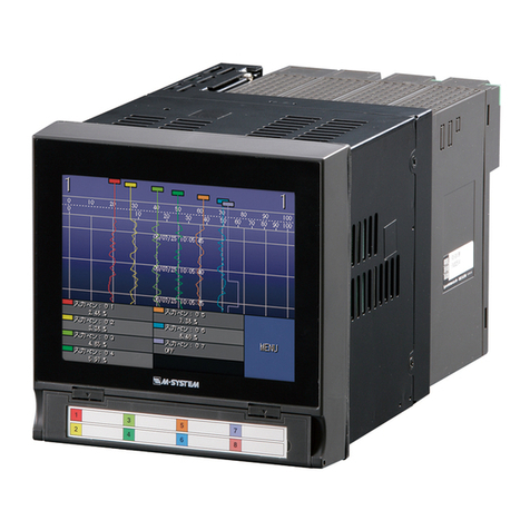
PAPERLESS RECORDER
(color LCD display) MODEL 71VR1
BEFORE USE ....
Thank you for choosing M-System. Before use, please check
contents of the package you received as outlined below.
If you have any problems or questions with the product,
please contact M-System’s Sales Office or representatives.
• This product is for use in general industrial environ-
ments, therefore may not be suitable for applications
which require higher level of safety (e.g. safety or accident
prevention systems) or of reliability (e.g. vehicle control or
combustion control systems).
• For safety, installation and maintenance of this product
must be conducted by qualified personnel.
■PACKAGE INCLUDES:
Paperless recorder (body + watertight packing)................(1)
Mounting bracket................................................................(2)
CJC sensor (for 71VR1- E501-x).........................................(3)
■MODEL NO.
Confirm Model No. marking on the product to be exactly
what you ordered.
■INSTRUCTION MANUAL
This manual describes necessary points of caution when
you use this product, including installation, connection and
basic maintenance procedures. For more details, refer to
the operating manual (EM-7403-B) downloadable at M-Sys-
tem’s web site: http://www.m-system.co.jp.
■MEMORY CARD
Prepare the following model numbers:
Available for purchase from M-System. Consult M-System.
• Manufacturer: Hagiwara Solutions
Model: NSD6-002GT (discontinued)
Capacity: 2 GB
• Manufacturer: Hagiwara Solutions
Model: NSD6-004GH(A00SDI (discontinued),
NSDA-004GT (discontinued),
NSDA-004GL (discontinued),
NSD6-004GH(B21SEI
Capacity: 4 GB
• Manufacturer: Apacer Technology
Model: AP-ISD04GIS4B-T (discontinued),
AP-ISD04GIS4B-3T
Capacity: 4 GB
POINTS OF CAUTION
■CONFORMITY WITH EU DIRECTIVES
• This equipment is suitable for Pollution Degree 2, Instal-
lation Category II (transient voltage 2500V) and Meas-
urement Category II (contact output, transient voltage
2500V). Reinforced insulation (analog input or contact
input or contact output or network interface to power to
FE: 300V) and basic insulation (analog input each other
or contact input or network interface to contact output
each other: 300V) are maintained. Prior to installation,
check that the insulation class of this unit satisfies the
system requirements.
• Altitude up to 2000 meters.
• Do not share the grounding point of PE (Protective Earth)
of other devices with FE (Functional Earth). Handle as
signal ground.
• The equipment must be installed such that appropriate
clearance and creepage distances are maintained to con-
form to CE requirements. Failure to observe these re-
quirements may invalidate the CE conformance.
• The actual installation environments such as panel con-
figurations, connected devices, connected wires, may af-
fect the protection level of this unit when it is integrated
in a panel system. The user may have to review the CE
requirements in regard to the whole system and employ
additional protective measures to ensure the CE conform-
ity.
• In order to enable the operator to turn off the power in-
put immediately, install a switch or a circuit breaker ac-
cording to the relevant requirements in IEC 60947-2 and
properly indicate it.
■POWER INPUT RATING & OPERATIONAL RANGE
• Locate the power input rating marked on the product and
confirm its operational range as indicated below:
100 – 240V AC rating: 85 – 264V, 50/60 Hz,
approx. 7VA at 100V AC
approx. 10VA at 240V AC
24V DC rating: 24V ±10%, approx. 6W
110V DC rating: 85 – 150V, approx. 6W
• Supplying any level of power other than specified above
can damage the unit or the power source.
• Power supply start-up characteristics must reach within
5 seconds to the operational voltage range of the unit.
• Power cables and signal I/O cables for the unit must be
located separately.
• Power cables, signal I/O cables and communication cables
for the unit should not be bundled together.
• To increase noise resistance of the power input wires,
twist the strands before connecting.
■GENERAL PRECAUTIONS
• Before you remove the unit, turn off the power supply and
I/O signals for safety.
• Do not disassemble or modify the unit in any way. Doing
so may result in a fire or an electrical shock.
• Do not block the unit’s ventilation openings or use it in
areas where heat accumulates.
Additionally, do not store or use it under high-tempera-
ture conditions.
