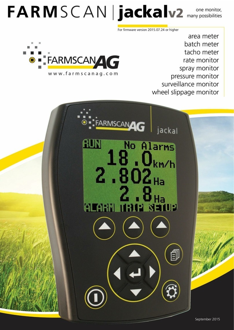
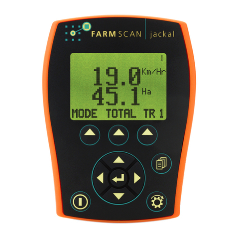
FARM SCAN jackal V3.5 User manual

TABLE OF CONTENTS
GENERAL DESCRIPTION..........................................................................................1
INSTALLATION .......................................................................................................2
CONNECTIONS.......................................................................................................3
OVERVIEW.............................................................................................................6
AREA & SPEED METER SETUP (WIZARD).................................................................9
AREA & SPEED METER USING GPS SETUP (WIZARD).............................................12
TACHOMETER - RPM METER SETUP (WIZARD).....................................................13
TRIPS...................................................................................................................15
ALARMS...............................................................................................................16
INPUTS ................................................................................................................16
FRONT SCREEN....................................................................................................16
OTHER SETTINGS (IMPLEMENT WIDTH) ...............................................................17
GPS/SERIAL..........................................................................................................18
ABOUT JACKAL.....................................................................................................18
DIAGNOSTICS ......................................................................................................18
FACTORY RESET...................................................................................................18
For Serial Numbers 30007000-7999
OCTOBER 2018

AM-JACKAL-B / OCT 2018 WWW.FARMSCANAG.COM 1
GENERAL DESCRIPTION
The Jackal Basic is capable of monitoring 3 functions simultaneously (2 inputs) –e.g. Speed/Area &
Tachometer. Input 1 –RPM Only / Input 2 –Speed/Area Only
The inputs can have both high and low alarm thresholds set which can trigger a visual and audible alarm if
necessary.
The unit employs a large daylight readable LCD to provide legible characters on the display and enable
calibration data to be clear and descriptive.
Our onboard calibration wizard makes setup a breeze! It’s simplified with the ability to enter either a factor
(pulses per unit) or simply drive/run a set amount whilst the unit is counting the pulses and let the system
calculate its own factor.
24 recordable trips allows the operator to track numerous jobs in a period of work.
Each input can be used to display information using imperial and metric units.
TECHNICAL SPECIFICATIONS
Specifications below are subject to change and are based on a Jackal with all features unlocked.
Power
Requirements
12
VDC
@
250mA
Display
128 x 64 Mono Graphic LCD
Operating Temperature
0 to
50
˚
c
Storage Temperature
-5 to
65
˚
c
Dimensions
135mm H
x
100mm W
x
30mm D
Sensor Inputs
9
Inputs 1-5 & 8-9
(Square Wave)
Up to 400 pulses per
second (On/Off/Freq)
Inputs 6-7
Analog Voltage
0 –
5V
GPS
TX/RX
Ground
2
Output PWM (Control Version Only)
2
Output +12v
1
Output
4
Output current rating
4A/output
DISCLAIMER
The warranty offered on this Farmscan Ag product is limited to the repair or replacement of the faulty
goods. No liability will be accepted for loss of profit or productivity.
WARRANTY IS VOID if power and or sensors are not connected as described in this guide.

2 WWW.FARMSCANAG.COM AM-JACKAL-B / OCT 2018
INSTALLATION
PARTS LIST
REF
PART NUMBER
DESCRIPTION
QTY
1
A-Jackal
Jackal Monitor
1
2
AH-407
Mounting Bracket
1
3
P-321 x1
P-322 x1
11 Way Input Plug
Green
Grey (Required if
using a Prox Sensor
or GPS)
4
AC-105
5m Power Cable
1
5
HM-506
Screw Driver
1
Not Pictured
AM-200
Warranty Card
1
Not Pictured
AM-Jackal
Manual
1
PARTS PICTORIAL
MOUNTING & INSTALLATION
The Jackal Basic is
provided
with a
suction window mount.
Slide
mount
onto unit and push
sideways
to lock into place. Make sure you hear a c
lick
of the
mount
locking
into
place.
Place in a
convenient position
on the
windscreen
and using the
toggle
lever
pictur
ed above (Item
2),
push all the way to the
bottom
until lever locks into
position.
Note:
Monitor should
be
mounted
in a clearly visible
position
in the cab for the
operator, but
not in
a
position where
it is
subject
to
intense
heat or
moistur
e.
1
2
3
4
5

AM-JACKAL-B / OCT 2018 WWW.FARMSCANAG.COM 3
CONNECTIONS
The connector on the rear of the Jackal Basic has the following connection points available for use
POWER CONNECTION
Power connection must come direct from the battery terminals. WARRANTY IS VOID if power is not
connected as described in this section.
1. Connect power cable supplied DIRECTLY TO BATTERY
2. Ring terminals are used for battery connection and the bare end used to connect to the rear Jackal.
(Refer above image for power connection)
3. Connect Ground to BATT -VE, Terminal B11 using the RED with BLACK stripe wire
4. Connect +12 Volts (+battery terminal) to BATT +VE, Terminal B10 using the red wire
5. Ensure that the battery connection to the Jackal is +12 Volts
Connecting 24V to the Jackal will VOID WARRANTY –12V ONLY
Disconnect the terminal plugs
from the Jackal if ARC
WELDING on machinery

4 WWW.FARMSCANAG.COM AM-JACKAL-B / OCT 2018
INSTALLING SENSORS
The following examples will help to determine appropriate sensor input connections into the Jackal.
NB: The Jackal Basic is Unlocked only for Input 1 –Fan or Shaft RPM & Input 2 –Wheel Speed & Area
TWO WIRE “REED” – BLACK END SENSOR WITH MAGNET
KIT # 1007P –WHEEL SENSOR (2 WIRE)
KIT # 2076 –SHAFT SENSOR (2 WIRE)
These kits will all include a “reed” type sensor. The reed type sensor is
a 2-wire sensor (normally black end) and only uses a ground/earth
wire and a signal wire.
•Insert the black ground wire into (A7) and the white/coloured
signal wire into (A2) for Wheel Input
•Insert the black ground wire into (A7) and the white/coloured
signal wire into (A1) for Shaft/RPM Input
Use the wizard to setup the port and calibrate the sensor once
installed.
THREE WIRE “PROX” – BLUE END SENSOR
KIT # AA-2010P –WHEEL OR FAN SENSOR (3 WIRE)
These kits will all include a “square wave” type sensor. The sensor is 3
wires and uses a ground/earth wire, a signal wire and a 12v power
wire.
•Insert the black ground wire into (A7) and the white/coloured
signal wire into (A2) for Wheel Input & (B5) for 12v Sensor
Power
•Insert the black ground wire into (A7) and the white/coloured
signal wire into (A1) for Shaft Input & (B5) for 12v Sensor
Power
Use the wizard to setup the port and calibrate a sensor once installed.
NB: A Proximity sensor can be used for wheel speed or RPM.

AM-JACKAL-B / OCT 2018 WWW.FARMSCANAG.COM 5
GPS
KIT #T-135
GPS units supplied from Farmscan Ag are pre-programmed and
ready to use with the Jackal Basic.
The diagram to the right shows which terminals to connect your
GPS to.
Insert the black wire to (B1) and the white or yellow wire into
(B11) and the red wire into (B5)
Use the wizard to setup the port and calibrate once installed
using the default baud rate of 19200 baud.
GGA, VTG, RMC supported.
An adapter cable is also available to purchase from Farmscan Ag –Part Number AC-135

6 WWW.FARMSCANAG.COM AM-JACKAL-B / OCT 2018
OVERVIEW
BUTTON FUNCTIONS
1. Power On/Off button
a. Power is
turned
on by pressing the ON/OFF button for 1 second.
b. Power is
turned
off by
holding the
ON/OFF
button for 2 seconds.
2. Run/Hold button
a. The RUN/HOLD button has a dual function.
a. Press RUN/HOLD once to place the ‘MONITOR ON HOLD’.
b. Press RUN/HOLD again to resume operation.
b. The RUN/HOLD state is indicated in the top left hand corner of the screen. When the monitor is in
RUN mode, the unit displays RUN to signify that the monitor is active.
c. When the monitor is in HOLD mode the unit displays the word “HOLD” & “BEEPS” every 2 seconds
3. Page button
a. The PAGE button is not used in the Jackal Basic (Control Only)
4. Select button (3 of)
a. The Jackal has 3 soft buttons placed directly under the LCD. These buttons will change function in
different menus.
b. The function of the soft button is indicated at the bottom of the screen directly above the button.
5. Navigation button (Up, Down, Left, Right, Enter)
a. The Round navigation (NAV) buttons are used to navigate UP/DOWN/LEFT/RIGHT in calibration screens
as well as scrolling through the display lines on the main screen.
b. ENTER is used to select the option highlighted onscreen.
4
3
1
2
5

AM-JACKAL-B / OCT 2018 WWW.FARMSCANAG.COM 7
SCREEN LAYOUT
The Jackal can display up to two or three lines of live information at any one time.
Using the middle NAV/Enter button allows you to toggle between the different display modes when multiple inputs
are being used.
Example : 2 Lines
Example : 3 Lines

8 WWW.FARMSCANAG.COM AM-JACKAL-B / OCT 2018
MAIN MENU
The level of Jackal unlock will determine what options are viewable and available to be edited.
Use the NAV button down to reveal further menu information
Wizard Run a predefined wizard for setting up the Jackal Basic as an Area Meter or Tachometer.
Inputs View what the inputs are setup as.
Front Screen Order the display lines on the front screen
Other Change implement width and units (cm,m, ft, yd, in, km, mi), alarm notification settings,
Settings simulate speed & language (English, French, German, Bulgarian).
GPS/Serial When an external GPS is connected view and ensure the GPS is setup correctly.
Setup baud rate and confirm GPS messages (NMEA messages RMC or GGA+VTG are
required) Latitude, Longitude, heading, speed, date & time.
About Jackal Shows current version of Jackal software and unlock codes installed on the unit.
Diagnostics Shows current input voltage, current draw and input diagnostics when activated.
Factory Reset Returns the Jackal to factory default.

AM-JACKAL-B / OCT 2018 WWW.FARMSCANAG.COM 9
AREA & SPEED METER SETUP (WIZARD) –INPUT 2
The Jackal can display Speed & Area in any combination of km/Ha or
mph/acre.
A pickup can be mounted either on a wheel hub or shaft. (Example image
right)
NB: THERE SHOULD BE A 5-10MM CLEARANCE
BETWEEN SENSOR AND MAGNET
Sensors Required
•Wheel sensor pickup 2 (Reed) or 3 wire (Proximity)
•Magnet (Used with 2 wire sensor)
Available Connections
REFER TO PAGE 4
SETUP
From the front screen press SETUP
Highlight WIZARD and press SELECT
Press NEXT
Choose your
calibration method
Select WHEEL
Leave the calibration method as
m/pulse
Auto Set > PAGE 10
Manual Ratio > PAGE 11
Reed
Switch
Prox
Switch

10 WWW.FARMSCANAG.COM AM-JACKAL-B / OCT 2018
CALIBRATION (AUTO SET)
1. Ensure that the sensor and pickup are end-end before continuing
2. Mark bottom centre of tyre on which the sensor is fitted and peg ground in corresponding position
3. Measure out a known distance to calibrate i.e. 20m
4. Peg the corresponding point i.e. at the 20m mark
Press the down arrow to
Select TARGET
Select EDIT
Using the NAV buttons enter
your measured distance. i.e.
20.0000
Press EXIT when done.
Press START and move
forward slowly.
This will allow pulses to
register.
When you arrive at the
center mark point of tyre to
peg press STOP
Press CALC. This will divide
the distance travelled by the
number of pules registered.
MANUAL RATIO will now be
updated.
Press NEXT
Using the NAV buttons select
how you would like the area
to be displayed on the front
screen.
Press NEXT
Press EDIT to change the
input name or
Press NEXT to continue
Select km/h or mph to
display the speed on the
front screen.
You have the option to set
Alarm Min/Max points if
required. Using the NAV
buttons select and EDIT as
required.
Press NEXT
Press EDIT to change the
input name or
Press NEXT to continue
Press the UP arrow to
highlight the width.
Press EDIT & use the NAV
buttons to change the
implement width. E.g. 12m.
Pressing EDIT will change the
Unit of Measure
Press NEXT.
Press EXIT & NEXT to
finalise the setup of the
Speed & Area Wizard.
If you have a 2nd sensor
connected to Input 1 press
NEXT to continue the
wizard.
THIS ENDS THE AUTO SET WIZARD SETUP FOR SPEED/AREA METER

AM-JACKAL-B / OCT 2018 WWW.FARMSCANAG.COM 11
CALIBRATION (MANUAL RATIO)
1. Ensure that the sensor and pickup are end-end before continuing
2. Mark bottom centre of tyre on which the sensor is fitted and mark ground in corresponding position
3. Drive ONE full rotation of the wheel, returning the mark point on tyre to bottom centre
4. Measure between the two points.
oThis is your Manual Ratio (Example 1.24m)
Select MANUAL RATIO 1.0
Select EDIT
Using the NAV buttons enter
your measured distance. i.e.
1.240000
Press EXIT when done.
Press NEXT
Using the NAV buttons
select how you would like
the area to be displayed on
the front screen. Press NEXT
Press EDIT to change the
input name or
Press NEXT to continue
Select km/h or mph to display
the speed on the front
screen.
You have the option to set
Alarm Min/Max points if
required. Using the NAV
buttons select and EDIT as
required. Press NEXT
Press EDIT to change the
input name or
Press NEXT to continue
Press the UP arrow to
highlight the width.
Press EDIT & use the NAV
buttons to change the
implement width. E.g. 12m.
Pressing EDIT will change the
Unit of Measure
Press NEXT.
Press EXIT & NEXT to finalise
the setup of the Speed &
Area Wizard.
If you have a 2nd sensor
connected to Input 1 press
NEXT to continue the wizard.
THIS ENDS THE MANUAL RATIO SET WIZARD SETUP FOR SPEED/AREA METER

12 WWW.FARMSCANAG.COM AM-JACKAL-B / OCT 2018
AREA & SPEED METER USING GPS SETUP (WIZARD)
The Jackal can display Speed & Area in any combination of km/Ha or mph/acre.
A wheel sensor is not required when using a GPS. GPS purchased from Farmscan
Ag are pre-programmed. If you BYO please ensure the following:
•GPS programmed with RMC –GGA - VTG NMEA messages.
•Any Baud Rate of - 4800,9600,19200,38400,115200
Available Connections - REFER TO PAGE 5
SETUP
From the front screen press
SETUP
Highlight WIZARD and press
SELECT
Press NEXT
Select GPS
Press the EDIT button to
change the baud rate, when
the correct baud rate is
selected the corresponding
NMEA message will be
acknowledged with a Y.
Press NEXT
Press EDIT to change the
input name or
Press NEXT to continue
Select km/h or mph to display
the speed on the front
screen.
You have the option to set
Alarm Min/Max points if
required. Using the NAV
buttons select and EDIT as
required. Press NEXT
If you have a 2nd sensor
connected to Input 1 press
NEXT to continue the
wizard.
Press EDIT to change the
input name or
Press NEXT to continue
Press the UP arrow to
highlight the width.
Press EDIT & use the NAV
buttons to change the
implement width. E.g. 12m.
Pressing EDIT will change the
Unit of Measure. Press NEXT.
Press EXIT & NEXT to finalise
the setup of the Speed &
Area Wizard.
THIS ENDS THE
SETUP FOR SPEED/AREA
METER USING
GPS INPUT

AM-JACKAL-B / OCT 2018 WWW.FARMSCANAG.COM 13
TACHOMETER - RPM METER SETUP (WIZARD) –INPUT 1
The Jackal can display an rpm (Revolutions per minute) which is useful for
monitoring fans or shafts.
NB: THERE SHOULD BE A 5-10MM CLEARANCE
BETWEEN SENSOR AND MAGNET OR 2-5MM BETWEEN PROX
AND PICKUP
Sensors Required
•Shaft Sensor pickup 2 (Reed) or 3 wire (Proximity)
•Magnet (Used with 2 wire sensor)
Available Connections
REFER TO PAGE 4
SETUP
From the front screen press
SETUP
Highlight WIZARD and press
SELECT
Press NEXT
Select SKIP
Select NEXT
Leave the default value of
pulse/rev
Select MANUAL RATIO
Select EDIT
The manual ratio is the
number of magnets (reed or
coil sensor) or bolt
heads/teeth (for proximity).
or Press NEXT
FOR LOW RPM
(1rpm-20rpm)
Press the DOWN button and
change VeryLowSpeed from
NO to YES by pressing EDIT
Press NEXT when done
Reed
Switch
Prox
Switch

14 WWW.FARMSCANAG.COM AM-JACKAL-B / OCT 2018
Leave the default value of
RPM.
Select NEXT
You have the option to set
Alarm Min/Max points if
required. Using the NAV
buttons select and EDIT as
required. Press NEXT
Press EDIT to change the
input name or
Press NEXT to continue
Press NEXT to finalise the
Wizard
THIS ENDS THE WIZARD SETUP FOR A TACHOMETER

AM-JACKAL-B / OCT 2018 WWW.FARMSCANAG.COM 15
TRIPS
The Trips page allows accumulating values to be saved and recalled at a later time.
From the front page press TRIP
The screen above allows you to SAVE/RESET individual
trips or view SAVED TRIPS
By pressing the SAVE/RESET you have the ability to
Reset Trip | Save Trip | Reset All
By pressing 2. Save Trip it will be stored in the
SAVED TRIPS option
You can now view the SAVED TRIPS. You also have the
ability to EDIT and name the Trip or DEL ALL
(Delete All Trips)
When you return to the TRIPS page the Trip will continue to accumulate. (Like above)
You will need to SAVE/RESET the trip if you want to start from Zero (0) again

16 WWW.FARMSCANAG.COM AM-JACKAL-B / OCT 2018
ALARMS
Alarms are set on a per input basis. High/Low Alarm points can be set for speed,
hectares and RPM. Alarms will be displayed visually and made audible.
To EDIT your alarms re-run the wizard by pressing SETUP from the front screen.
Your existing settings will not be lost during the wizard re-run.
When an alarm has been tripped, the front screen will display the line number and name of the triggered function.
Example 1. In this example, an alarm is tripped when
the speed goes under 2km/h. The input number and
function name are displayed on the top right and will
continue to flash along with the function line.
Example 2. This Jackal has been setup to alarm
whenever the RPM reaches above 120rpm. In this
example, the rpm has gone above the max value to
132rpm and will notify the user until the rpm goes
below this value.
INPUTS
Inputs are the calibration factors used to
display the values correctly on the front
screen.
To EDIT your inputs re-run the wizard by
pressing SETUP from the front screen.
Your existing settings will not be lost during
the wizard re-run.
FRONT SCREEN
The front screen menu allows you to order the front screen line items. Highlight the line you wish to move, press
ORDER (a *will appear to the left) then press PLACE to accept when you have chosen the new order.

AM-JACKAL-B / OCT 2018 WWW.FARMSCANAG.COM 17
OTHER SETTINGS (IMPLEMENT WIDTH)
The other settings allows you to edit the following options:
•Implement EDIT your implement width here to update your
Width working hectares.
•AlarmBeep EDIT this value to change the number of seconds
between each audible alarm.
•AlarmOnHold EDIT this value to change if the alarm is activate or not
when the Jackal is on hold.
•Language EDIT this value to change the Jackal’s language.

18 WWW.FARMSCANAG.COM AM-JACKAL-B / OCT 2018
GPS/SERIAL
The GPS/Serial menu allows you to confirm
that the GPS connected to the Jackal is
function correctly.
By pressing the SETUP, confirm the correct
strings and Baud rate.
To EDIT GPS settings re-run the wizard by
pressing SETUP from the front screen.
Your existing settings will not be lost during the wizard re-run.
ABOUT JACKAL
Displays the Firmware version that’s installed on the Jackal.
This screen also allows you to UNLOCK your Jackal to further functionality.
Please contact Farmscan Ag should you wish to purchase an unlock code.
DIAGNOSTICS
This screen provides the following information:
•Voltage Displays a live input voltage to the Jackal.
•Current Displays live Current draw on the Jackal.
•Input “x” When inputs are enabled, they will also
be displayed for easy diagnostics.
FACTORY RESET
WARNING
This screen allows you to return the Jackal to factory defaults.
All values will be lost after pressing RESET.
Power cycle the Jackal to confirm all settings are reset.

This manual suits for next models
1
Table of contents
Other FARM SCAN Measuring Instrument manuals
Popular Measuring Instrument manuals by other brands

Inficon
Inficon Sniffer line SL3000XL Translation of the original operating instructions

Veris Industries
Veris Industries E51H2 installation guide

Tektronix
Tektronix 7L5 instruction manual

LumaSense
LumaSense IS 8 pro manual

Sifos Technologies
Sifos Technologies PSA-3000 installation guide

Svantek
Svantek SVAN 106 user manual