INSTALLING SENSORS
The following examples will help to determine appropriate sensor input connections into the Jackal.
TWO WIRE “REED” SENSOR KITS
1007P, 2009, 2076
These kits will all include a “reed” type sensor. The reed type
sensor is a 2 wire sensor (normally black end) and only uses a
ground/earth wire and a signal wire.
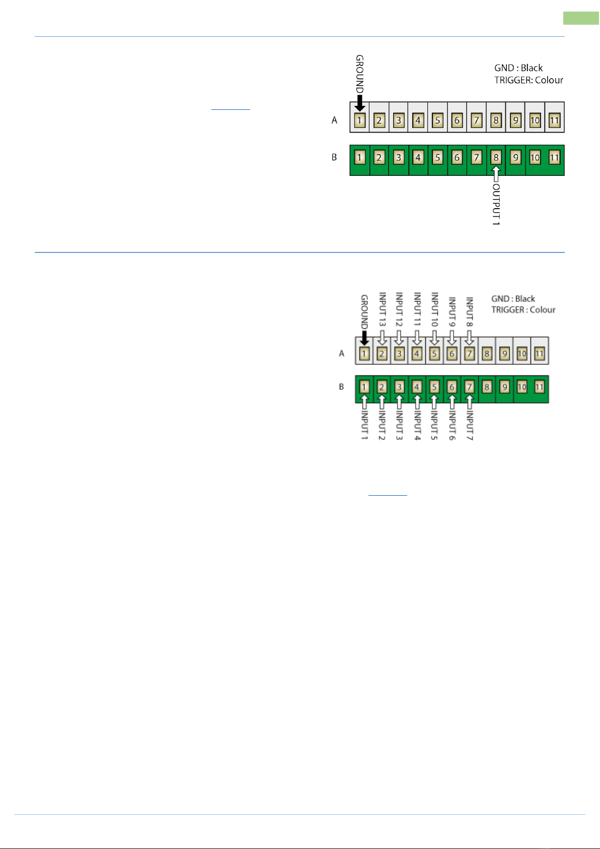
The diagram to the right shows which terminals to connect
your sensors to. If the ground/earth (A1) terminal already has
a wire from another sensor applied to it then you will need to
piggy back onto this wire. If the signal port (B2-B6) has wires
from another sensor applied to it then move to one of the
ports shown that is free.
Use the wizard to setup the port and calibrate a sensor once installed.
TWO WIRE “COIL” OR FLOW SENSOR KITS
2034, 2077, AA-230S/RCS
These kits will all include a “coil” type sensor. The coil type
sensor is a 2 wire sensor (normally yellow end) and only uses a
ground/earth wire and a signal wire. A 2 wire sine wave flow
sensor input can also be used, found in the 2” AA-231 kit.
The diagram to the right shows which terminals to connect
your sensors to. If the ground/earth (A1) terminal already has
a wire from another sensor applied to it then you will need to
piggy back onto this wire.
NB : There is only ONE (1) coil input on the Jackal
Use the wizard to setup the port and calibrate a sensor once installed.
TWO & THREE WIRE “REED/PROX/FLOW” SENSOR KITS
AA-2010P, AA-123P, AA-125, AA-242, AA-230X, AA-232X, AA-231
These kits will all include a “reed” type “proximity” sensor or
“square wave” flow sensor input. The proximity or flow sensor
(Rapid Check) is a 3 wire sensor and uses a ground/earth wire, a
signal wire and a 12v power wire. All reed style are two wire.
The diagram to the right shows which terminals to connect your
sensors to. If the ground/earth (A1) or regulated 12v power (OUT2,
B9) terminal already has a wire from another sensor applied to it
then you will need to piggy back onto this wire. If the signal ports
(B2-B6) has wires from another sensor applied to it then move to
one of the ports shown that is free.
Use the wizard to setup the port and calibrate a sensor once installed.