Farmhand 70LB Planning guide
1
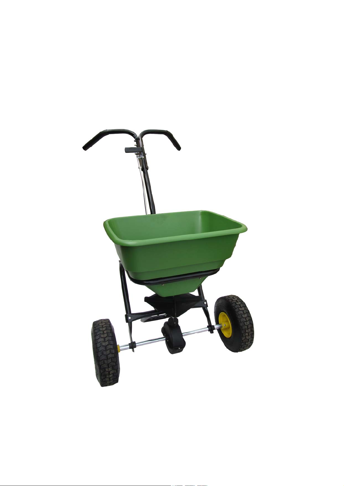
70LB WALK-BEHIND
SPREADER
ASSEMBLY AND OPERATING INSTRUCTION
SAVE THESE INSTRUCTIONS FOR FUTURE REFERENCE

2
General Warnings and Rules............................................................................3
Hazard Signal Word Definitions........................................................................4
Controls and Features Identification .................................................................5
Component & Hardware..............................................................................6,7
Assembly Instructions..............................................................8, 9 10, 11,12,13
Operation Instructions..........................................................................14, 15,16
Spreading Instructions ....................................................................................17
Maintenance and Storage...............................................................................18
Specification....................................................................................................18
Parts Drawing & Parts List .........................................................................19,20

3
GENERAL WARNINGS
READ and UNDERSTAND this manual completely before using Push Spreader.
Operator must read and understand all safety and warning information, operating instructions,
maintenance and storage instructions before operating this equipment. Failure to properly operate and
maintain the push spreader could result in serious injury to the operator or bystanders.
Operation Warnings
Do not at any time carry passengers sit or stand on the spreader.
Do not allow children to play on, stand upon or climb in the spreader.
Always inspect the spreader before using to assure it is in good working condition.
Replace or repair damaged or worn parts immediately.
Always check and tighten hardware and assembled parts before operation.
Do not exceed equipment maximum load capacity of 80lb.
Avoid large holes and ditches when transporting loads.
Be careful when operating on steep grades (hill) the spreader may tip over.
Do not push close to creeks, ditches and public highways.
Do not use spreader on windy days when spreading grass seed or herbicides.
Always use caution when loading and unloading spreader.
Never tow the spreader with a motorized vehicle.
. Crush and Cut Hazards
Always keep hands and feet clear from moving parts while operating the equipment.
Always clear and keep work area clean when operating.
Always wear safety gear, eye protection, gloves and work boots when operating the spreader.
.
WARNING
The warnings, cautions, and instructions outlined in this instruction manual cannot cover all
possible conditions or situations that may occur. It must be understood by the operator that
common sense and caution are factors which cannot be built into this product and must be
supplied by the operator.
Assembly Is Required
This product requires assembly before use. See “Assembly” section for instructions. Because of the
weight and/or size of the push spreader, it is recommended that another adult be present to assist
with the assembly. INSPECT ALL COMPONENTS closely upon receipt to make sure no components
are missing or damaged.
4
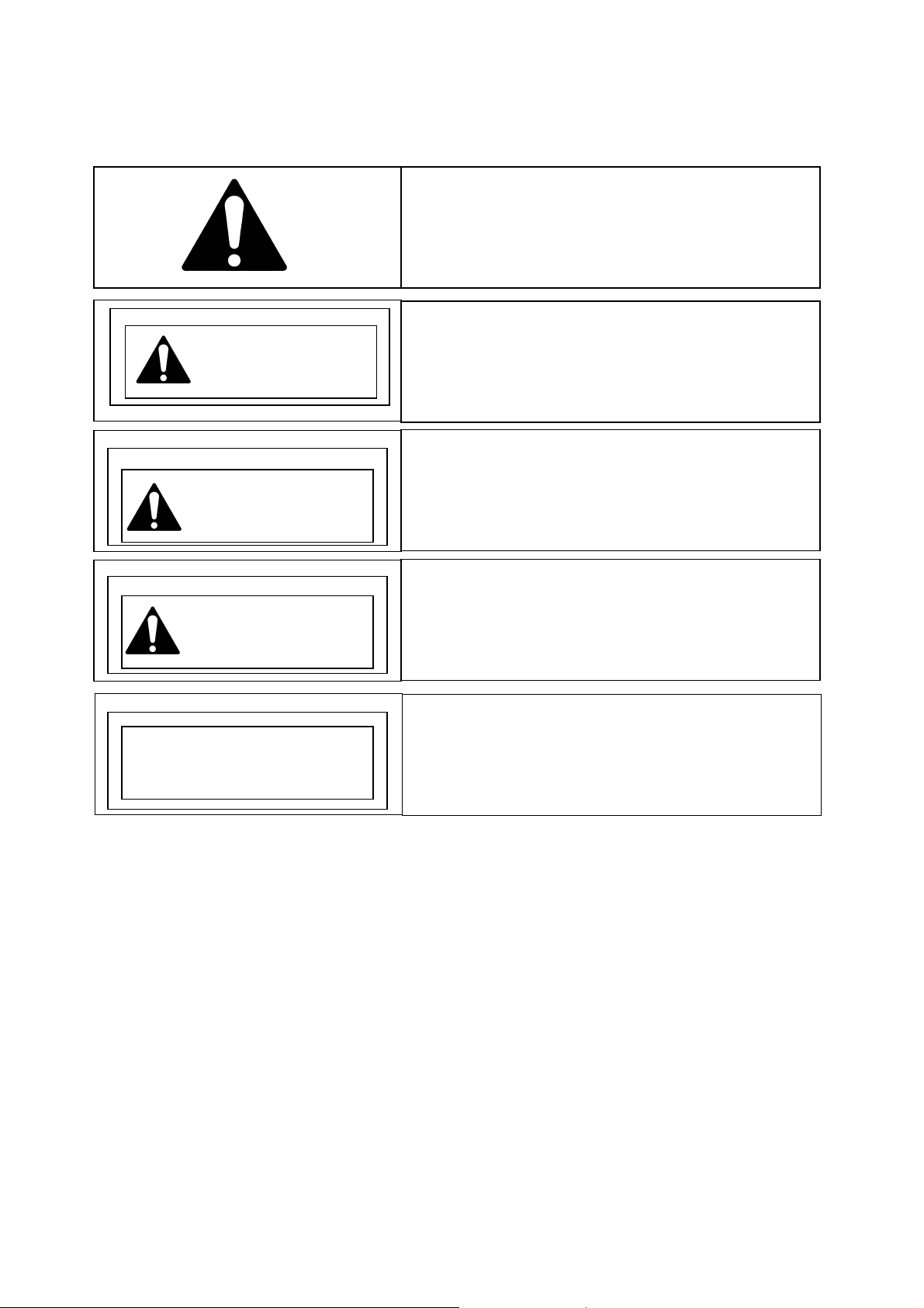
Hazard Signal Word Definitions
ABOUT YOUR PUSH SPREADER
This push spreader is designed to spreader a wide range of materials (Fertilizer, Grass Seed and Ice melt).
Materials such as Powders, Manure, Top Soil, Gravel, and Mulch have the wrong physical characteristics
and should not be used with this spreader. Never exceed the rated load capacity of 80lbs when operating
the spreader.
Your spreader needs to be pushed at three miles per hour, which is a brisk walking speed. Slower or faster
speeds will change the spread patterns. Wet spreading material will also change the spread pattern and
flow rate. Clean your spreader thoroughly after each use. Wash between the shut off plate and bottom of
the hopper.
Technical specifications on the push spreader are provided in the “Specifications” section of this manual.
This is the safety alert symbol. It is used to alert
you to potential personal injury hazards. Obey
all safety messages that follow this symbol to
avoid possible injury or death.
DANGER indicates an imminently hazardous
situation which, if not avoided, will result in
death or serious injury.
DANGER
WARNING indicates a potentially hazardous
situation which, if not avoided, could result in
death or serious injury.
WARNING
CAUTION indicates a potentially hazardous
situation which, if not avoided, may result in
minor or moderate injury.
CAUTION
CAUTION used without the safety alert symbol
indicates a potentially hazardous situation
which, if not avoided, may result in property
CAUTION

5
Read this owner’s manual before operating the equipment. Familiarize yourself with the location and
function of the controls and features. Save this manual for future reference.
1) Flow Control – Controls the flow of material being spread.
2) T-Handle – Pushes and moves the spreader easily.
3) Support Leg – Stabilizes load and spreader.
4) Tires / Wheel – Do not exceed recommended rated 25 PSI.
5) Impeller - Evenly distributes material.
6) Hopper – Do not exceed rated load capacity 80lb
CAUTION
Read and follow all instructions for assembly and operation. Failure to properly assemble this
equipment could result in serious injury to the user or bystanders, or cause equipment damage.
Controls and Features Identification
1
2
3
4
5
6

6
PUSH SPREADER COMPONENT PARTS AND ASSEMBLY
Take all parts out of the shipping crate and inspect components to ensure there are no missing pieces before
starting to assemble the push spreader follow steps 1 through 7.
TOOLS REQUIRED
Rubber or Wooden Hammer
8mm Wrenches (2 Each)
6mm Wrenches (2 Each)
Phillips Screw Driver
Pliers
Com
p
onent Parts
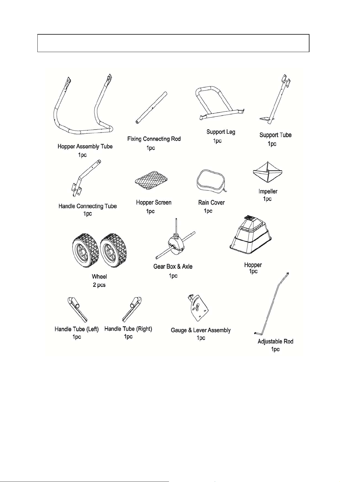
7
Com
p
onent Parts

8
STEP 1: Slide Gearbox Support Bracket (16A) onto Gear Box & Axle assembly (27). Install
Impeller (16) onto Gear Box & Axle assembly (27). Insert screw M4x20 through impeller
then through Gear Box Axle.
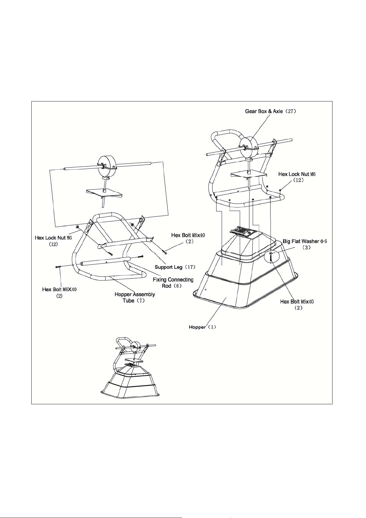
Assembly Instructions
9
STEP 2: Attach the Wheel Assembly Frame on each side of the Gear Box Axle and Fixing
Connecting Rod, insert Hex Bolt M6x40 into the Fixing Connecting Rod through Wheel
Assembly Frame. Make sure the hole on Axle of Gear Box is on the right side when
assembly as shown. Attach Wheel Assembly Frames and Support Leg onto Hopper by
using Hex Bolt M6x40, Hex Lock Nut M6 and Big Flat Washers Ø6. Note: The bolts and
nuts needn't be tightened yet.

10
STEP 3: Install Left WheelAssembly, Wheel Spacer Bush and Inner Axle Bushing to Left Axle
by using bolt M6x40 and lock nut M6, Now install Right Wheel Assembly to Right Axle,
and then secure with Flat Washer Ø16 and Cotter Pin Ø4x30.
Table of contents
Popular Spreader manuals by other brands


Fisher
Fisher POLY-CASTER 78601 owner's manual

TurfEx
TurfEx RS7200 Owner's/operator's manual

Ferris
Ferris Pathfinder Series Operator's manual

Fayat Group
Fayat Group DYNAPAC S100 operation & maintenance

Art's-Way Manufacturing
Art's-Way Manufacturing X700 Operator's manual & parts list

EASTMAN
EASTMAN CR 500 instruction manual


